Siemens SIMATIC ET 200eco PN M12-L Equipment Manual
Hide thumbs
Also See for SIMATIC ET 200eco PN M12-L:
- Operating instructions manual (278 pages) ,
- Compact operating instructions (156 pages) ,
- System manual (127 pages)
Table of Contents
Advertisement
Quick Links
Advertisement
Table of Contents

Related Manuals for Siemens SIMATIC ET 200eco PN M12-L


Summary of Contents for Siemens SIMATIC ET 200eco PN M12-L
- Page 2 Digital inputs/outputs DIQ 16x24VDC/0.5A/2A M12-L 8xM12 (6ES7143-6BH00-0BB0) Preface ET 200eco PN M12-L Documentation Guide SIMATIC Product overview Wiring ET 200eco PN Digital inputs/outputs DIQ PROFINET IO 16x24VDC/0.5A/2A M12-L 8xM12 (6ES7143-6BH00-0BB0) EtherNet/IP Equipment Manual Modbus TCP Technical specifications Dimension drawing 02/2022 A5E46571210-AC...
- Page 3 Note the following: WARNING Siemens products may only be used for the applications described in the catalog and in the relevant technical documentation. If products and components from other manufacturers are used, these must be recommended or approved by Siemens. Proper transport, storage, installation, assembly, commissioning, operation and maintenance are required to ensure that the products operate safely and without any problems.
-
Page 4: Preface
Preface Purpose of the documentation This equipment manual supplements the ET 200eco PN M12-L Distributed I/O System (https://support.industry.siemens.com/cs/ww/en/view/109778292) system manual. Functions that relate in general to the distributed I/O devices ET 200eco PN M12-L are described in this system manual. - Page 5 Siemens' products and solutions undergo continuous development to make them more secure. Siemens strongly recommends that product updates are applied as soon as they are available and that the latest product versions are used. Use of product versions that are no longer supported, and failure to apply the latest updates may increase customers' exposure to cyber threats.
-
Page 6: Table Of Contents
Table of contents Preface ..............................3 ET 200eco PN M12-L Documentation Guide ..................7 Product overview ..........................11 Properties .......................... 11 Operator controls and display elements ................14 Wiring ..............................15 Terminal and block diagram ....................15 Pin assignment ........................16 PROFINET IO ............................ - Page 7 Table of contents Technical specifications ........................67 Dimension drawing ..........................76 Dimension drawing......................76 Digital inputs/outputs DIQ 16x24VDC/0.5A/2A M12-L 8xM12 (6ES7143-6BH00-0BB0) Equipment Manual, 02/2022, A5E46571210-AC...
-
Page 8: Et 200Eco Pn M12-L Documentation Guide
This arrangement enables you to access the specific content you require. Basic information The system manual describes in detail the configuration, installation, wiring and commissioning of the SIMATIC ET 200eco PN M12-L distributed I/O system. The STEP 7 online help supports you in the configuration and programming. Device information... - Page 9 You must register once to use the full functionality of "mySupport". You can find "mySupport" on the Internet (https://support.industry.siemens.com/My/ww/en). Application examples The application examples support you with various tools and examples for solving your automation tasks.
- Page 10 You can find the SIMATIC Automation Tool on the Internet (https://support.industry.siemens.com/cs/ww/en/view/98161300). PRONETA SIEMENS PRONETA (PROFINET network analysis) allows you to analyze the plant network during commissioning. PRONETA features two core functions: • The topology overview automatically scans the PROFINET and all connected components.
- Page 11 ET 200eco PN M12-L Documentation Guide SINETPLAN SINETPLAN, the Siemens Network Planner, supports you in planning automation systems and networks based on PROFINET. The tool facilitates professional and predictive dimensioning of your PROFINET installation as early as in the planning stage. In addition, SINETPLAN supports you during network optimization and helps you to exploit network resources optimally and to plan reserves.
-
Page 12: Product Overview
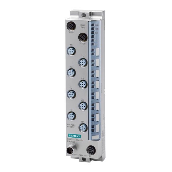
Product overview Properties Article number 6ES7143-6BH00-0BB0 View of the I/O device Figure 2-1 View of the I/O device DIQ 16x24VDC/0.5A/2A M12-L 8xM12 Digital inputs/outputs DIQ 16x24VDC/0.5A/2A M12-L 8xM12 (6ES7143-6BH00-0BB0) Equipment Manual, 02/2022, A5E46571210-AC... - Page 13 Product overview 2.1 Properties Properties The I/O device has the following technical properties: • Using the MultiFieldbus function, it connects the ET 200eco PN M12-L distributed I/O system with one of the following bus protocols: – PROFINET IO – EtherNet/IP –...
- Page 14 • Connectors and cables • M12 sealing cap See also You can find additional information on the accessories in the ET 200eco PN M12-L distributed I/O system (https://support.industry.siemens.com/cs/ww/en/view/109778292) system manual. Digital inputs/outputs DIQ 16x24VDC/0.5A/2A M12-L 8xM12 (6ES7143-6BH00-0BB0) Equipment Manual, 02/2022, A5E46571210-AC...
-
Page 15: Operator Controls And Display Elements
Product overview 2.2 Operator controls and display elements Operator controls and display elements The figure below shows the operator controls and display elements of the DIQ 16x24VDC/0.5A/2A M12-L 8xM12 I/O device. ① PN/MF (LAN): Sockets for connecting MultiFieldbus ② RN/NS: RUN/network status LED ③... -
Page 16: Wiring
Wiring Terminal and block diagram The figure below shows an example of the pin assignment of signal outputs and signal inputs with single and dual assignment of the sockets. Digital inputs/outputs DIQ 16x24VDC/0.5A/2A M12-L 8xM12 (6ES7143-6BH00-0BB0) Equipment Manual, 02/2022, A5E46571210-AC... -
Page 17: Pin Assignment
Wiring 3.2 Pin assignment ① Bus interface with integrated 2-port switch Supply voltage 1L+ (non-switched) ② Monitoring Ground 1M (non-switched) ③ DIQ circuit (1L+, 1M) Load voltage 2L+ (switched) ④ DIQ circuit (2L+, 2M1) Ground 2M (switched) ⑤ Internal supply voltage Ground with reverse polarity protection, divert- ed from 2M (switched) ⑥... - Page 18 Wiring 3.2 Pin assignment Pin assignment of the sockets for digital inputs/digital outputs The tables below show the pin assignments of the 8 sockets for connection of the digital inputs/digital outputs. Table 3- 2 Pin assignment for digital inputs/digital outputs Assignment Front view of the sockets X10 to X13 - sockets for digital inputs/digital...
- Page 19 Wiring 3.2 Pin assignment NOTICE 24 V encoder supply 2U Use only the 24 V encoder supply 2U provided by the I/O device to supply power to the encoders. NOTICE Reverse polarity protection To guarantee reverse polarity protection, use the ground 2M supplied by the I/O device at pin 3 of the respective socket.
-
Page 20: Profinet Io
PROFINET IO Parameters/address space 4.1.1 Parameters The table below shows the parameters for the I/O device DIQ 16x24VDC/0.5A/2A M12-L 8xM12. Table 4- 1 Configurable parameters and their defaults (GSD file) Parameters Value range Default Scope with configuration soft- ware, e.g. STEP 7 (TIA Portal) Diagnostics: Undervoltage 1L+ Disable Channel... -
Page 21: Explanation Of The Parameters
PROFINET IO 4.1 Parameters/address space Parameters Value range Default Scope with configuration soft- ware, e.g. STEP 7 (TIA Portal) Configuration mode Channel • • Reaction to CPU STOP Shutdown Channel • Shutdown (Digital outputs) • Keep last value • Output substitute value 1 4.1.2 Explanation of the parameters... - Page 22 PROFINET IO 4.1 Parameters/address space Diagnostics: Wire break detection and alarm Activates wire break detection and enabling of diagnostics for the digital input. In the event of an interruption of the line between the encoder and I/O device, a diagnostic message is generated.
-
Page 23: Address Space
PROFINET IO 4.1 Parameters/address space 4.1.3 Address space The DIQ 16x24VDC/0.5A/2A M12-L 8xM12 I/O device can be configured differently; see following table. Depending on the configuration, additional/different addresses are assigned in the process images. Configuration options of the DIQ 16x24VDC/0.5A/2A M12-L 8xM12 I/O device You can configure the I/O device digital inputs/digital outputs with STEP 7 (TIA Portal) or with a GSD file. - Page 24 PROFINET IO 4.1 Parameters/address space Address space for configuration as 1 x 16-channel DIQ 16x24VDC The following figure shows the address space allocation for the configuration as 16-channel I/O device with digital inputs/digital outputs without value status. The start address for the I/O device can be assigned freely.
- Page 25 PROFINET IO 4.1 Parameters/address space Address space for configuration as 1 x 16-channel DIQ 16x24VDC QI The following figure shows the address space allocation for the configuration as 16-channel I/O device with digital inputs/digital outputs with value status. The start address for the I/O device can be assigned freely.
- Page 26 PROFINET IO 4.1 Parameters/address space Address space for configuration as 1 x 16-channel DIQ 16x24VDC MSI/MSO The 1st submodule (= basic submodule) behaves like a 1 x 16-channel DIQ 16x24VDC. The value status (Quality Information, QI) is always activated for the submodule. Diagnostics and hardware interrupts are signaled for this submodule.
- Page 27 PROFINET IO 4.1 Parameters/address space The following figure shows the assignment of the address space with submodules 1 and 2 and the value status. Figure 4-3 Address space for configuration as 1 x 16-channel DIQ 16x24VDC MSI/MSO with value status (basic submodule) Digital inputs/outputs DIQ 16x24VDC/0.5A/2A M12-L 8xM12 (6ES7143-6BH00-0BB0) Equipment Manual, 02/2022, A5E46571210-AC...
- Page 28 PROFINET IO 4.1 Parameters/address space Figure 4-4 Address space for configuration as 1 x 16-channel DIQ 16x24VDC MSI/MSO with value status (MSI/MSO submodule) Digital inputs/outputs DIQ 16x24VDC/0.5A/2A M12-L 8xM12 (6ES7143-6BH00-0BB0) Equipment Manual, 02/2022, A5E46571210-AC...
- Page 29 You can find information on the functionality Module-internal Shared Input/Shared Output (MSI/MSO) in the STEP 7 online help or in the function manual SIMATIC PROFINET with STEP 7 (https://support.industry.siemens.com/cs/ww/en/view/49948856). Digital inputs/outputs DIQ 16x24VDC/0.5A/2A M12-L 8xM12 (6ES7143-6BH00-0BB0) Equipment Manual, 02/2022, A5E46571210-AC...
-
Page 30: Interrupts/Diagnostics Alarms
PROFINET IO 4.2 Interrupts/diagnostics alarms Interrupts/diagnostics alarms 4.2.1 Status and error displays LED displays The figure below shows the LED displays (status and error displays) of the I/O device DIQ 16x24VDC/0.5A/2A M12-L 8xM12. ① RN/NS: RUN/network status LED ② ER/MS: ERROR/module status LED ③... - Page 31 PROFINET IO 4.2 Interrupts/diagnostics alarms Meaning of the LEDs The following tables set out the meaning of the status and error displays. Measures for dealing with diagnostics alarms can be found in the section Diagnostics alarms (Page 32). Behavior of the LEDs RN/NS (RUN/network status), ER/MS (ERROR/module status) and MT/IO (MAINT/IO status) on PROFINET Table 4- 3 Error display of the LEDs...
- Page 32 PROFINET IO 4.2 Interrupts/diagnostics alarms PWR LED Table 4- 4 Status display of the PWR LED PWR LED Meaning Load voltage 2L+ is missing or too low Load voltage 2L+ present P1 LK and P2 LK LEDs Table 4- 5 Error display of the P1 LK and P2 LK LEDs LEDs Meaning...
-
Page 33: Interrupts
PROFINET IO 4.2 Interrupts/diagnostics alarms 4.2.2 Interrupts The I/O device digital inputs DIQ 16x24VDC/0.5A/2A M12-L 8xM12 supports diagnostic and maintenance interrupts. Diagnostic interrupt The I/O device generates a diagnostic interrupt on the following events: • Wire break • Internal module fault •... - Page 34 PROFINET IO 4.2 Interrupts/diagnostics alarms Table 4- 7 Diagnostics alarms, their meanings and corrective measures Diagnostics alarm Error code Meaning Corrective measures Wire break Fault in the external circuitry Check the external circuitry and correct the fault. Encoder faulty Replace the encoder. Impedance of encoder circuitry is too high Use a different encoder type or modify the wiring.
-
Page 35: Maintenance Events
PROFINET IO 4.2 Interrupts/diagnostics alarms 4.2.3.2 Maintenance events Triggering of a maintenance event The MultiFieldbus interfaces of the ET 200eco PN M12-L support the diagnostics concept and maintenance concept in PROFINET according to the IEC 61158-6-10 standard. The goal is to detect and remove potential problems as soon as possible. -
Page 36: Hardware Interrupts
PROFINET IO 4.2 Interrupts/diagnostics alarms 4.2.3.3 Hardware interrupts During a hardware interrupt, the CPU interrupts processing of the user program and processes the hardware interrupt organization block. For detailed information on the event, refer to the hardware interrupt organization block with the "RALRM"... -
Page 37: Ethernet/Ip
EtherNet/IP Functions/parameters/address space 5.1.1 Supported EtherNet/IP functions Supported functions The table below shows the functions that the module supports with EtherNet/IP. Supported functions Remarks I/O communication with scanner FW 5.1.x or higher Parameter assignment FW 5.1.x or higher Reading diagnostics FW 5.1.x or higher Normative CIP objects FW 5.1.x or higher... -
Page 38: Parameters
EtherNet/IP 5.1 Functions/parameters/address space Supported CIP objects for EtherNet/IP The table below shows the functions that the module supports with EtherNet/IP. Supported CIP object Remarks Identity object FW 5.1.x or higher Assembly object FW 5.1.x or higher Connection Manager object FW 5.1.x or higher TCP/IP Interface object FW 5.1.x or higher... -
Page 39: Explanation Of The Parameters
EtherNet/IP 5.1 Functions/parameters/address space Parameters Value range Default Effective range with configuration software, for example, MFCT Hardware interrupt on falling edge Disable Channel • Disable (Digital inputs) • Enable Configuration mode Channel • • Reaction to CPU STOP Shutdown Channel •... - Page 40 EtherNet/IP 5.1 Functions/parameters/address space Diagnostics: Wire break detection and alarm Activates wire break detection and enabling of diagnostics for the digital input in case of an interruption of the cable between the encoder and I/O device. Note • This diagnostics is only available for channels configured as inputs. •...
-
Page 41: Update Time Of The I/O Data
EtherNet/IP 5.1 Functions/parameters/address space 5.1.4 Update time of the I/O data You can estimate the typical update time for an I/O cycle as follows: RPI timer (settable from 2 to 20 ms ± 10 %) default 10 ms + I/O processing (typically 1.4 ms, ± 1 ms jitter due to free-running cycles) + EM conversion (dependent on cycle time and parameter assignment of the module) If necessary, you must take into account other influences caused by the EIP scanner and network components by adding them. - Page 42 EtherNet/IP 5.1 Functions/parameters/address space Address space for configuration as 1 x 16-channel DIQ 16x24VDC The following figure shows the address space allocation for the configuration as 16-channel I/O device with digital inputs/digital outputs without value status. The addresses of the channels are derived from the start address.
- Page 43 EtherNet/IP 5.1 Functions/parameters/address space Address space for configuration as 1 x 16-channel DIQ 16x24VDC QI The following figure shows the address space allocation for the configuration as 16-channel I/O device with digital inputs/digital outputs with value status. The addresses of the channels are derived from the start address.
- Page 44 EtherNet/IP 5.1 Functions/parameters/address space Address space for configuration as 1 x 16-channel DIQ 16x24VDC MSI/MSO The 1st submodule (= basic submodule) behaves like a 1 x 16-channel DIQ 16x24VDC. The value status (Quality Information, QI) is always activated for the submodule. Diagnostics and hardware interrupts are signaled for this submodule.
- Page 45 EtherNet/IP 5.1 Functions/parameters/address space The following figure shows the assignment of the address space with submodules 1 and 2 and the value status. Figure 5-3 Address space for configuration as 1 x 16-channel DIQ 16x24VDC MSI/MSO with value status (basic submodule) Digital inputs/outputs DIQ 16x24VDC/0.5A/2A M12-L 8xM12 (6ES7143-6BH00-0BB0) Equipment Manual, 02/2022, A5E46571210-AC...
- Page 46 EtherNet/IP 5.1 Functions/parameters/address space Figure 5-4 Address space for configuration as 1 x 16-channel DIQ 16x24VDC MSI/MSO with value status (MSI/MSO submodule) Digital inputs/outputs DIQ 16x24VDC/0.5A/2A M12-L 8xM12 (6ES7143-6BH00-0BB0) Equipment Manual, 02/2022, A5E46571210-AC...
- Page 47 EtherNet/IP 5.1 Functions/parameters/address space Address space for configuration as 2 x 8-channel DIQ 16x24VDC S The figure below shows the address space assignment for configuration as a 2 x 8-channel I/O device with digital inputs/digital outputs without value status. Figure 5-5 Address space for configuration as 2 x 8-channel DIQ 16x24VDC S without value status Digital inputs/outputs DIQ 16x24VDC/0.5A/2A M12-L 8xM12 (6ES7143-6BH00-0BB0) Equipment Manual, 02/2022, A5E46571210-AC...
- Page 48 5.1 Functions/parameters/address space Reference You can find information about the Module Internal Shared Input/Shared Output (MSI/MSO) functionality in the MultiFieldbus (https://support.industry.siemens.com/cs/ww/en/view/109773209) Function Manual SIMATIC PROFINET with STEP 7 (https://support.industry.siemens.com/cs/ww/en/view/49948856). Digital inputs/outputs DIQ 16x24VDC/0.5A/2A M12-L 8xM12 (6ES7143-6BH00-0BB0) Equipment Manual, 02/2022, A5E46571210-AC...
-
Page 49: Diagnostics
EtherNet/IP 5.2 Diagnostics Diagnostics 5.2.1 Status and error displays for EtherNet/IP LED displays The figure below shows the LED displays (status and error displays) of the I/O device DIQ 16x24VDC/0.5A/2A M12-L 8xM12. ① RN/NS: RUN/network status LED ② ER/MS: ERROR/module status LED ③... - Page 50 EtherNet/IP 5.2 Diagnostics Behavior of the LEDs RN/NS (RUN/network status), ER/MS (ERROR/module status) and MT/IO (MAINT/IO status) on EtherNet/IP The LEDs display the status with the highest priority if there are different LED states due to overlaid events. (0 = off, 1 = green flashing, 2 = green, 3 = yellow, 4 = red flashing, 5 = red) The following table shows the meaning of the RN/NS, ER/MS LEDs and MT/IO LEDs for EtherNet/IP: Table 5- 3...
- Page 51 EtherNet/IP 5.2 Diagnostics LEDs Meaning Remedy Hardware or firmware defective. • You can read out the service data Flashes Flashes Flashes with MFCT. The "Node flash test" is running (the P1 LK and P2 LK LEDs are also flashing). Flashes Flashes Flashes PWR LED...
- Page 52 EtherNet/IP 5.2 Diagnostics Channel status/channel error LED Table 5- 6 Status and error display of the channel status/channel error LED LEDs Meaning Channel status/channel error Process value = 0 Process value = 1 Channel diagnostics Digital inputs/outputs DIQ 16x24VDC/0.5A/2A M12-L 8xM12 (6ES7143-6BH00-0BB0) Equipment Manual, 02/2022, A5E46571210-AC...
-
Page 53: Modbus Tcp
Modbus TCP Functions/parameters/address space 6.1.1 Supported Modbus TCP functions Supported functions The table below shows the functions that the module supports with Modbus TCP. Supported functions RegLayoutVer- Remarks sion I/O communication with Modbus client V1.0 FW 5.1.x or higher Free user registers (e.g. for coordination of the redundancy) V1.0 FW 5.1.x or higher Device information... -
Page 54: Parameters
Modbus TCP 6.1 Functions/parameters/address space 6.1.2 Parameters The table below shows the parameters for the I/O device DIQ 16x24VDC/0.5A/2A M12-L 8xM12. Table 6- 1 Configurable parameters and their defaults (GSD file) Parameters Value range Default Effective range with configura- tion software, for example, MFCT Diagnostics: Undervoltage 1L+ Disable... -
Page 55: Explanation Of The Parameters
Modbus TCP 6.1 Functions/parameters/address space 6.1.3 Explanation of the parameters Diagnostics: Undervoltage 1L+ Enabling of the diagnostics for insufficient supply voltage 1L+. Diagnostics: Missing 2L+ Enabling of the diagnostics for missing or insufficient load voltage 2L+. Note This diagnostics is only available for channels supplied with 2L+ voltage. Diagnostics: Short-circuit Enable diagnostics: •... -
Page 56: Update Time Of The I/O Data
Modbus TCP 6.1 Functions/parameters/address space Hardware interrupt on rising edge Specifies whether a hardware interrupt is generated via the data status on a rising edge on the channel. The hardware interrupt information can be read and confirmed via CIP Ethernet/IP. Hardware interrupt on falling edge Specifies whether a hardware interrupt is generated via the data status on a falling edge on the channel. -
Page 57: Address Space
Modbus TCP 6.1 Functions/parameters/address space 6.1.5 Address space The DIQ 16x24VDC/0.5A/2A M12-L 8xM12 I/O device can be configured differently; see following table. Depending on the configuration, additional/different addresses are assigned in the process images. Configuration options of the DIQ 16x24VDC/0.5A/2A M12-L 8xM12 I/O device When the I/O device is configured using a GSD file, the configurations are available under different short designations/device names in the device view of MFCT. - Page 58 Modbus TCP 6.1 Functions/parameters/address space Address space for configuration as 1 x 16-channel DIQ 16x24VDC The following figure shows the address space allocation for the configuration as 16-channel I/O device with digital inputs/digital outputs without value status. The addresses of the channels are derived from the start address.
- Page 59 Modbus TCP 6.1 Functions/parameters/address space Address space for configuration as 1 x 16-channel DIQ 16x24VDC QI The following figure shows the address space allocation for the configuration as 16-channel I/O device with digital inputs/digital outputs with value status. The addresses of the channels are derived from the start address.
- Page 60 Modbus TCP 6.1 Functions/parameters/address space Address space for configuration as 1 x 16-channel DIQ 16x24VDC MSI/MSO The 1st submodule (= basic submodule) behaves like a 1 x 16-channel DIQ 16x24VDC. The value status (Quality Information, QI) is always activated for the submodule. Diagnostics and hardware interrupts are signaled for this submodule.
- Page 61 Modbus TCP 6.1 Functions/parameters/address space The following figure shows the assignment of the address space with submodules 1 and 2 and the value status. Figure 6-3 Address space for configuration as 1 x 16-channel DIQ 16x24VDC MSI/MSO with value status (basic submodule) Digital inputs/outputs DIQ 16x24VDC/0.5A/2A M12-L 8xM12 (6ES7143-6BH00-0BB0) Equipment Manual, 02/2022, A5E46571210-AC...
- Page 62 Modbus TCP 6.1 Functions/parameters/address space Figure 6-4 Address space for configuration as 1 x 16-channel DIQ 16x24VDC MSI/MSO with value status (MSI/MSO submodule) Digital inputs/outputs DIQ 16x24VDC/0.5A/2A M12-L 8xM12 (6ES7143-6BH00-0BB0) Equipment Manual, 02/2022, A5E46571210-AC...
- Page 63 Modbus TCP 6.1 Functions/parameters/address space Address space for configuration as 2 x 8-channel DIQ 16x24VDC S The figure below shows the address space assignment for configuration as a 2 x 8-channel I/O device with digital inputs/digital outputs without value status. Figure 6-5 Address space for configuration as 2 x 8-channel DIQ 16x24VDC S without value status Digital inputs/outputs DIQ 16x24VDC/0.5A/2A M12-L 8xM12 (6ES7143-6BH00-0BB0)
- Page 64 6.1 Functions/parameters/address space Reference You can find information about the Module Internal Shared Input/Shared Output (MSI/MSO) functionality in the MultiFieldbus (https://support.industry.siemens.com/cs/ww/en/view/109773209) Function Manual SIMATIC PROFINET with STEP 7 (https://support.industry.siemens.com/cs/ww/en/view/49948856). Digital inputs/outputs DIQ 16x24VDC/0.5A/2A M12-L 8xM12 (6ES7143-6BH00-0BB0) Equipment Manual, 02/2022, A5E46571210-AC...
-
Page 65: Diagnostics
Modbus TCP 6.2 Diagnostics Diagnostics 6.2.1 Status and error displays for Modbus TCP LED displays The figure below shows the LED displays (status and error displays) of the I/O device DIQ 16x24VDC/0.5A/2A M12-L 8xM12. ① RN/NS: RUN/network status LED ② ER/MS: ERROR/module status LED ③... - Page 66 Modbus TCP 6.2 Diagnostics Behavior of the LEDs RN/NS (RUN/network status), ER/MS (ERROR/module status) and MT/IO (MAINT/IO status) on modbus TCP The LEDs display the status with the highest priority if there are different LED states due to overlaid events. (0 = off, 1 = green flashing, 2 = green, 3 = yellow, 4 = red flashing, 5 = red) The following table shows the meaning of the RN/NS, ER/MS LEDs and MT/IO LEDs for Modbus TCP: Table 6- 3...
- Page 67 Modbus TCP 6.2 Diagnostics PWR LED Table 6- 4 Status display of the PWR LED PWR LED Meaning Load voltage 2L+ is missing or too low Load voltage 2L+ present P1 LK and P2 LK LEDs Table 6- 5 Error display of the P1 LK and P2 LK LEDs LEDs Meaning Remedy...
- Page 68 Technical specifications of the I/O device DIQ 16x24VDC/0.5A/2A M12-L 8xM12 The following table shows the technical specifications as of the issue date. You can find a data sheet including daily updated technical specifications on the Internet (https://support.industry.siemens.com/cs/de/en/pv/6ES7143-6BH00-0BB0/td?dl=en). Article number 6ES7143-6BH00-0BB0...
- Page 69 Technical specifications Article number 6ES7143-6BH00-0BB0 Supply voltage power supply according to NEC Class 2 required Load voltage 1L+ 24 V • Rated value (DC) 20.4 V • permissible range, lower limit (DC) 28.8 V • permissible range, upper limit (DC) Yes;...
- Page 70 Technical specifications Article number 6ES7143-6BH00-0BB0 Input voltage 24 V • Rated value (DC) -3 to +5V • for signal "0" +11 to +30V • for signal "1" Input current 2.4 mA • for signal "1", typ. Input delay (for rated value of input voltage) for standard inputs –...
- Page 71 Technical specifications Article number 6ES7143-6BH00-0BB0 Switching frequency 0.5 A: 100 Hz / 2 A: 40 Hz • with resistive load, max. 0.5 Hz • with inductive load, max. 1 Hz • on lamp load, max. Total current of the outputs 1L+: 2 A / 2L+: 6 A •...
- Page 72 Technical specifications Article number 6ES7143-6BH00-0BB0 PROFINET IO Device Services – Yes; 250 µs to 4 ms in 125 µs frame – Prioritized startup – Shared device – Number of IO Controllers with shared de- vice, max. Redundancy mode • PROFINET system redundancy (S2) –...
- Page 73 Technical specifications Article number 6ES7143-6BH00-0BB0 Modbus TCP Services – read coils (code=1) – read discrete inputs (code=2) – Read Holding Registers (Code=3) – write single coil (code=5) – write multiple coils (code=15) – Write Multiple Registers (Code=16) – Parameter change by master –...
- Page 74 Technical specifications Article number 6ES7143-6BH00-0BB0 Diagnostics indication LED Yes; green LED • RUN LED Yes; red LED • ERROR LED Yes; Yellow LED • MAINT LED Yes; green/red LED • NS LED Yes; green/red LED • MS LED Yes; red-green-yellow LED •...
- Page 75 Technical specifications Article number 6ES7143-6BH00-0BB0 Altitude during operation relating to sea level Up to max. 5 000 m, at installation height > 2 000 • Ambient air temperature-barometric pressure- m additional restrictions altitude connection method / header Design of electrical connection 4/5-pin M12 circular connectors Design of electrical connection for the inputs and M12, 5-pin, A-coded...
- Page 76 Technical specifications Note Adherence to the minimum clearance The I/O devices may be used at an installation distance of 2 cm up to max. 60 °C ambient temperature. If the installation distance to other devices or objects is less than 2 cm, the ambient temperature must be reduced by 5 K (for example, 60 °C ⇒...
- Page 77 Dimension drawing Dimension drawing The figure below shows the dimension drawing of the DIQ 16x24VDC0.5A/2A M12-L 8xM12 digital input/output module in front and side views. Figure A-1 Dimension drawing Digital inputs/outputs DIQ 16x24VDC/0.5A/2A M12-L 8xM12 (6ES7143-6BH00-0BB0) Equipment Manual, 02/2022, A5E46571210-AC...
Need help?
Do you have a question about the SIMATIC ET 200eco PN M12-L and is the answer not in the manual?
Questions and answers