Table of Contents
Advertisement
Quick Links
Advertisement
Table of Contents

Related Manuals for Smartgen FPC1700


Summary of Contents for Smartgen FPC1700
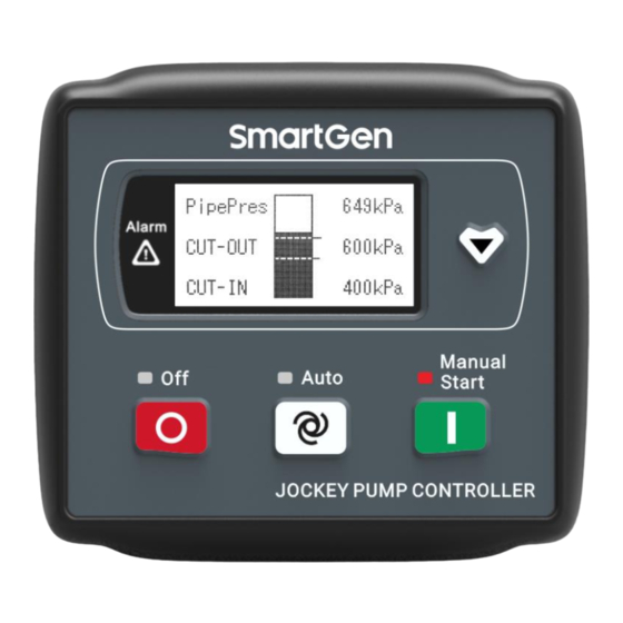
- Page 1 FPC1700 JOCKEY PUMP CONTROLLER USER MANUAL...
-
Page 2: Table Of Contents
7.2 AUTO MODE ..........................13 7.3 MANUAL MODE ..........................14 8 TERMINAL DESCRIPTION ......................... 14 9 TYPICAL APPLICATION ........................15 10 INSTALLATION DIMENSIONS ......................16 11 TROUBLE SHOOTING ........................17 FPC1700 Jockey Pump Controller User Manual Page 2 of 17... - Page 3 All rights reserved. No part of this publication may be reproduced in any material form (including photocopying or storing in any medium by electronic means or other) without the written permission of the copyright holder. SmartGen reserves the right to change the contents of this document without prior notice. Table 1 Software Version Date...
- Page 4 Indicates a procedure or practice, which, if not strictly observed, could result in CAUTION! damage or destruction of equipment. Indicates a procedure or practice, which could result in injury to personnel or loss of life if not followed correctly. WARNING! FPC1700 Jockey Pump Controller User Manual Page 4 of 17...
-
Page 5: Overview
1 OVERVIEW FPC1700 Jockey Pump Controller is composed of a microprocessor as the core, which can be started/stopped according to the pipe pressure, stabilize the pipe pressure in the setting range and detect the grid voltage to protect the abnormal voltage, realizing the automation and intelligent control of the controller. -
Page 6: Specification
Back Panel: IP20 Apply AC2.2kV voltage between high voltage terminal and low voltage Insulation terminal. The leakage current is not more than 3mA within 1min. Weight 0.16 kg FPC1700 Jockey Pump Controller User Manual Page 6 of 17... -
Page 7: Operation
Off mode: light on OFF Mode Other mode: light off Auto mode: light on Auto Mode Other mode: light off Manual mode: light on Manual Mode Other mode: light off FPC1700 Jockey Pump Controller User Manual Page 7 of 17... -
Page 8: Keys Functions
The contents displayed on main screen when sensor is digital: Pressure switch status The running status of jockey pump Voltage status Phase voltage Line voltage Frequency Current mode, alarm information FPC1700 Jockey Pump Controller User Manual Page 8 of 17... -
Page 9: Status Description
The frequency is less than the setting lower limit. Loss of Phase Loss of single- phase or 2-phase among A, B, C. Reverse Phase Phase sequence wrong of A-B-C. Sequence FPC1700 Jockey Pump Controller User Manual Page 9 of 17... -
Page 10: Main Menu
Content 0: kPa 1: bar Unit (0-3) 2: psi 3: MPa Shutdown when pipe pressure is greater 1000 kPa (0-9000) kPa than the cut-out pressure threshold value. Cut-out Pressure (0-3600)s FPC1700 Jockey Pump Controller User Manual Page 10 of 17... - Page 11 (80-200)% Over Freq. Return 104% Value 0: Disable Under Freq. Enable (0-1) 1: Enable Under Freq. Setting Value (80-200)% Under Freq. Return Value 0: Simplified Chinese Language (0-1) 1: English FPC1700 Jockey Pump Controller User Manual Page 11 of 17...
- Page 12 4: Auto mode output (0-9) Type 5: Manual mode output 6: Reserved 7: Reserved 8: Reserved 9: Reserved 0: Normally open output Output Action Type (0-1) 1: Normally close output FPC1700 Jockey Pump Controller User Manual Page 12 of 17...
-
Page 13: Function Description For Digital Input Ports
FPC1700 Jockey Pump Controller User Manual Page 13 of 17... -
Page 14: Manual Mode
AC 24V power supply Capacity 8A AC250V volts free Aux. Output Aux. output port output Null If it is single phase input, only AC 3P4W voltage input connect to A, N FPC1700 Jockey Pump Controller User Manual Page 14 of 17... -
Page 15: Typical Application
9 TYPICAL APPLICATION Fig.3 Typical Application Diagram of Single Phase Power Supply Fig.4 Typical Application Diagram of 3-Phase Power Supply FPC1700 Jockey Pump Controller User Manual Page 15 of 17... -
Page 16: Installation Dimensions
10 INSTALLATION DIMENSIONS This control is panel built-in design, fix it by clips during mounting. Unit: mm Fig.5 Case Dimensions and Panel Cutout Fig.6 Clips Installation FPC1700 Jockey Pump Controller User Manual Page 16 of 17... -
Page 17: Trouble Shooting
Controller alarm is available; Unreasonable setting of cut-in/cut-out pressure threshold value; No output of relay The start inhibit of input port is active; The working mode is on OFF mode. _________________________________ FPC1700 Jockey Pump Controller User Manual Page 17 of 17...
Need help?
Do you have a question about the FPC1700 and is the answer not in the manual?
Questions and answers