Table of Contents
Advertisement
Quick Links
Advertisement
Table of Contents

Subscribe to Our Youtube Channel
Related Manuals for Smartgen APC615


Summary of Contents for Smartgen APC615
- Page 1 APC615 PUMP UNIT CONTROLLER USER MANUAL SMARTGEN (ZHENGZHOU) TECHNOLOGY CO.,LTD.
- Page 2 SmartGen Technology at the address above. Any reference to trademarked product names used within this publication is owned by their respective companies. SmartGen Technology reserves the right to change the contents of this document without prior notice. Table 1- Software Version Date...
- Page 3 APC615 Pump Unit Controller User Manual This user manual only suits for APC615 controller. Table 2 - Notation Clarification Symbol Instruction Highlights an essential element of a procedure to ensure correctness. NOTE Indicates a procedure or practice, which, if not strictly observed, could result in CAUTION damage or destruction of equipment.
-
Page 4: Table Of Contents
APC615 Pump Unit Controller User Manual CONTENT OVERVIEW ............................6 2 PERFORMANCE AND CHARACTERISTICS ..................6 3 SPECIFICATION ........................... 7 4 OPERATION ............................8 PUSH BUTTONS DESCRIPTION ................... 8 INDICATOR LIGHT ........................9 AUTO START/STOP OPERATION ..................10 4.3.1 AUTOMATIC START SEQUENCE................10 4.3.2... - Page 5 APC615 Pump Unit Controller User Manual 13 CONNECTIONS OF CONTROLLER WITH J1939 ENGINE ............. 47 13.1 CUMMINS ISB/ISBE ......................47 13.2 CUMMINS QSL9 ........................47 13.3 CUMMINS QSM11 ......................... 47 13.4 CUMMINS QSX15-CM570 ....................48 13.5 CUMMINS GCS-MODBUS ....................48 13.6 CUMMINS QSM11 .........................
-
Page 6: Overview
APC615 Pump Unit Controller User Manual OVERVIEW APC615 Pump Unit Controller is designed for pump systems which controlled by engine. It allows automatic start/stop, data measurement, alarm protection as well as remote control, remote measurement and remote communication function. Utilizing the GOV (Engine Speed Governor) control function, the controller is able to stabilize the outlet/inlet pressure via regulating engine speed. -
Page 7: Specification
APC615 Pump Unit Controller User Manual All output ports are relay-out; Parameter setting: parameters can be modified and stored in internal FLASH memory and cannot be lost even in case of power outage; Multiple crank disconnect conditions (speed sensor, oil pressure) are optional;... -
Page 8: Operation
APC615 Pump Unit Controller User Manual Items Content voltage terminal; The leakage current is not more than 3mA within 1min. Weight 0.70kg OPERATION 4.1 PUSH BUTTONS DESCRIPTION Table 4 – Keys Function Icons Function Description 1.Stop running pump unit in Auto/Manual mode;... -
Page 9: Indicator Light
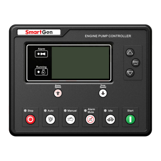
APC615 Pump Unit Controller User Manual 4.2 INDICATOR LIGHT Fig.1 – APC615 Front Panel Note: Selected indicators description: Common warning indicator: flash slowly when warning alarms occur; flash quickly when shutdown alarms occur; light is off when there are no alarms. -
Page 10: Auto Start/Stop Operation
APC615 Pump Unit Controller User Manual 4.3 AUTO START/STOP OPERATION 4.3.1 AUTOMATIC START SEQUENCE Press and indicator besides it illuminate, which means pump unit is in Auto Start mode. If remote input is active, controller “Start Delay” begins countdown, meanwhile, “Remote Start Warning”... -
Page 11: Manual Stop Sequence
APC615 Pump Unit Controller User Manual accelerates to high-speed running automatically; If high temperature, low oil pressure and over speed occur during pump unit running, controller can protect it to stop quickly (Please refer to 4.3.1, No.c~h of AUTO START OPERATION for detail procedures) 4.4.2 MANUAL STOP SEQUENCE... -
Page 12: Electric Driven Pump Start/Stop Operation
APC615 Pump Unit Controller User Manual time of “Waiting Pressure To”, fuel relay outputs, and after 1s (default fuel time before cranking) later, starter relay will output. The remaining stop process is the same as auto stop procedure (details please to see 4.3.1, No. d~h of AUTO START OPERATION). - Page 13 APC615 Pump Unit Controller User Manual Display Description Adjust speed type set as 2: CAN Adjust Speed; adjust speed Adj Speed Mode: Manual stabilize object set as 1: Inlet Pressure; display screen is showed as Speed 1500RPM 0.0% left. In this screen, users can select adjust speed mode (manual or...
-
Page 14: Protection
APC615 Pump Unit Controller User Manual CAN adjust speed controls the speed of the EFI engine via CAN port. when CAN adjust speed is selected, output center (SW1) need to be set as 5.0, and output range (SW2) need to be set as 2.0. -
Page 15: Shutdown Alarm
APC615 Pump Unit Controller User Manual Type Description upper limit of outlet pressure warning threshold, it will initiate a warning alarm. When the controller detects that the sensor value has fallen below the Low Outlet Pressure lower limit of outlet pressure warning threshold, it will initiate a warning alarm. - Page 16 APC615 Pump Unit Controller User Manual Type Description Fail Shutdown initiate a shutdown alarm. Engine Temperature When the controller detects that the temperature sensor is open circuit and the action select “Shutdown”, it will initiate a shutdown alarm. Sensor Open Circuit...
-
Page 17: Connections
APC615 Pump Unit Controller User Manual NOTE: ECU warning and ECU shutdown illustration: if detailed alarm content displayed on the LCD of controller, please check engien condition according to the displayed content; otherwise, please look up engine user manual based on the SPN code to receive information. - Page 18 APC615 Pump Unit Controller User Manual Function Cable Size Description Aux. Output 3 1.5mm see Table 10. 10~19 NC 1.5mm Relay normally open volt free contactor Aux. Output 4 1.5mm with rated 7A, volt free output. 1.5mm Relay normally open volt free contactor Aux.
- Page 19 APC615 Pump Unit Controller User Manual Function Cable Size Description Aux. Input 2(B) 0.5 mm Ground connected is active (B-) items please to see Table 11. Aux. Input 3(C) 0.5 mm Ground connected is active (B-) Aux. Input 4(D) 0.5 mm Ground connected is active (B-) Aux.
-
Page 20: Definition And Range Of Parameters
DEFINITION AND RANGE OF PARAMETERS 7.1 PARAMETER CONTENTS AND RANGE Items Parameter Default Description Language Language (0-2) 0: Simplified Chinese; 1:English; 2:Other Timers Time from remote start signal is active to start Start Delay (0-3600)s the pump unit. Time from remote stop signal is deactivated to Return Delay (0-3600)s stop the pump unit. - Page 21 APC615 Pump Unit Controller User Manual Items Parameter Default Description port is configured as “Fuel Pre-supply”, it is Interval Time interval time from the pre-supply output is completed to the next pre-supply output. If this time is configured as “0”, fuel pre-supply doesn’t output in standby status.
- Page 22 APC615 Pump Unit Controller User Manual Items Parameter Default Description Over (0-1000)% Speed Value Shutdown Delay (0-3600)s Setting value is percentage of rated speed, and return value and delay value can be set. Under (0-1000)% Value Speed Shutdown Delay (0-3600)s...
- Page 23 APC615 Pump Unit Controller User Manual Items Parameter Default Description CAUTION: Factory default password “00318”, operator can change the password to avoid nonprofessionals modification. Please keep in mind of the new password, if forget, please contact with factory service personnel.
- Page 24 APC615 Pump Unit Controller User Manual Items Parameter Default Description Curve Type (0-15) SGD. See table 12. Open Circuit Action (0-2) 0: Warning; 1: Shutdown; 2: No action 0: ℃; 1: ℉ Display Unit (0-1) It is can be set if fuel unit select “L”.
- Page 25 APC615 Pump Unit Controller User Manual Items Parameter Default Description or not, return value, and delay value can be set. (0-9000)% Warning when value of external connected sensor is lower than this value. Alarm enabled Low Warning or not, return value, and delay value can be set.
- Page 26 APC615 Pump Unit Controller User Manual Items Parameter Default Description this value. Alarm enabled or not, return value, and delay value can be set. Users should set the corresponding curve Custom Curve when select resistor curve type or current curve type.
- Page 27 APC615 Pump Unit Controller User Manual Items Parameter Default Description Contents Setting (0-239) Start relay output. See table 10. Active Type (0-1) 0:Normally open; 1:Normally close Relay Output Port 4 Contents Setting (0-239) Fuel relay output. See table 10. Active Type (0-1) 0:Normally open;...
-
Page 28: Definition Content Of Relay Output Ports
APC615 Pump Unit Controller User Manual 7.2 DEFINITION CONTENT OF RELAY OUTPUT PORTS Table 10 – Definition of Relay Output 1-6 Type Description Not Used Custom Period 1 Custom Period 2 Custom Period 3 Custom Period 4 Custom Period 5 Custom Period 6 Details of function description please see the following. - Page 29 APC615 Pump Unit Controller User Manual Type Description started completely. Action while genset is starting and disconnect while waiting for Fuel Relay stop. Used for engine which has idles. It closes before starting and opens when enters into warming up status; and it closes during...
- Page 30 APC615 Pump Unit Controller User Manual Type Description When suction pump type set as “D-driven Suction Pump”, Diesel Driven Pump Stop “Diesel Driven Pump Stop” output. When suction pump type set as “E-driven Suction Pump”, it is Electric Driven Pump Start output when electric driven suction pump starts and stops output when electric driven suction pump closes down.
- Page 31 APC615 Pump Unit Controller User Manual Type Description Over Flow Shutdown Action when over flow shutdown alarms occur. Over Flow Warning Action when over flow warning alarms occur. Outlet Pressure High Action when outlet pressure high warning alarms occur. Warning...
-
Page 32: Custom Period Output
APC615 Pump Unit Controller User Manual 7.2.1 CUSTOM PERIOD OUTPUT Defined Period output is composed by 2 parts, period output S1 and condition output S2. While S1 and S2 are TRUE synchronously, OUTPUT; While S1 or S2 is FALSE, NOT OUTPUT. -
Page 33: Defined Contents Of Configurable Input Ports
APC615 Pump Unit Controller User Manual 7.3 DEFINED CONTENTS OF CONFIGURABLE INPUT PORTS Table 11 – Definition of Digital Input Ports Type Description Including following functions, Indication: indicate only, not warning or shutdown. Warning: warning only, not shutdown. Shutdown: alarm and shutdown immediately Users Configured Never: input inactive. - Page 34 APC615 Pump Unit Controller User Manual Type Description External Charge Fail When this input is active, controller will initiate charge fail warning Input alarms. High Temperature Connect to sensor digital input port. Shutdown Pressure Connect to sensor digital input port.
-
Page 35: Selection Of Sensors
APC615 Pump Unit Controller User Manual 7.4 SELECTION OF SENSORS Table 12 – Sensors Selection Type Description Remark 0 Not used 1 Custom Res Curve 2 Custom 4-20mA curve 3 Custom Volt Curve 4 VDO 5 CURTIS Defined resistance’s range... - Page 36 APC615 Pump Unit Controller User Manual Note: User should open the shell of controller to change the jumper plug if your pump unit fitted with 4~20mA sensor. Fig.3 – Jumper Plug Transition Diagram Table 13 – Sensor Type Conversion Reistor-type...
-
Page 37: Conditions Of Crank Disconnect Selection
APC615 Pump Unit Controller User Manual 7.5 CONDITIONS OF CRANK DISCONNECT SELECTION Table 14 – Crank Disconnect Conditions Selection Setting description Engine Speed Oil Pressure Oil Pressure + Engine Speed NOTE: ─ There are 3 conditions to make starter disconnected with engine. Engine speed sensor and oil pressure both can be used separately. -
Page 38: Maintenance
APC615 Pump Unit Controller User Manual 7.6 MAINTENANCE Table 15 – Maintenance Settings Items Content Description Used for setting the current maintenance Enable Select 0:Disable; 1:Enable function. time interval between enabled Maintenance Interval (0-30000)h maintenance to need to maintenance. 0:No Action;... -
Page 39: Parameters Setting
APC615 Pump Unit Controller User Manual PARAMETERS SETTING for 3s to enter into “Parameter Configure” After controller is powered up, hold and press menue, and menue items are as follows, >Return >Parameter Config. > Language >Event Log >Module Info Select “Parameter Config.” Item to enter into parameters setting screen after entering the correct password (default 00318). - Page 40 APC615 Pump Unit Controller User Manual Over Shutdown to change “+” or “-“ of the parameter. Screen 6: Pressing Enable Choose: Enable SetVal: +00098 Pressing to continue setting the next digit until all digits are set DelayVal: 00003s completed. Then pressing enters into delay value setting, If it doesn’t need to change, press...
-
Page 41: Sensor Select
APC615 Pump Unit Controller User Manual SENSOR SELECT ─ When reselect sensors, the sensor curve will be transferred into the standard value. For example, if temperature sensor is SGD (120°C resistor type), its sensor curve is SGD (120°C resistor type);... -
Page 42: Commissioning
If everything goes well, genset will normal running after idle running (if idle run be set). During this time, please watch for engine’s running situations If there is any other question, please contact SmartGen’s service. APC615 Pump Unit Controller Version 1.0... -
Page 43: Typical Application
APC615 Pump Unit Controller User Manual 11 TYPICAL APPLICATION Fig. 5 - APC615 Typical Application Diagram Fig. 6 – Typical Application with Diesel Driven Suction Pump APC615 Pump Unit Controller Version 1.0 2017-10-20 Page 43 of 54... - Page 44 APC615 Pump Unit Controller User Manual Fig. 7 – Typical Application with Electric Driven Suction Pump APC615 Pump Unit Controller Version 1.0 2017-10-20 Page 44 of 54...
-
Page 45: Installation
─ Battery Voltage Input APC615 controller can suit for widely range of battery voltage DC(8~35)V. Negative of battery must be connected with the engine shell soundly. The diameter of wire which from power supply to battery must be over 2.5mm . - Page 46 APC615 Pump Unit Controller User Manual All outputs of controller are relay contact output type. If need to expand the relays, please add freewheel diode to both ends of expand relay’s coils (when coils of relay has DC current) or add resistance-capacitance return circuit (when coils of relay has AC current), in order to prevent disturbance to controller or others equipment.
-
Page 47: Connections Of Controller With J1939 Engine
APC615 Pump Unit Controller User Manual 13 CONNECTIONS OF CONTROLLER WITH J1939 ENGINE 13.1 CUMMINS ISB/ISBE Table 17 – Connector B Terminals of controller Connector B Remark Fuel relay output Start relay output Connect with starter coil directly Expand relay,... -
Page 48: Cummins Qsx15-Cm570
APC615 Pump Unit Controller User Manual CAN(H) Using 120Ω impedance connecting wire. CAN(L) Using 120Ω impedance connecting wire. Engine type: Cummins ISB 13.4 CUMMINS QSX15-CM570 It is suitable for CM570 engine control module. Engine type is QSX15. Table 23 – 50 Pins Connector... -
Page 49: Cummins Qsz13
APC615 Pump Unit Controller User Manual 13.7 CUMMINS QSZ13 Table 28 – Engine OEM Connector Terminals of controller OEM connector of engine Remark Fuel relay output Starter relay output Connect to starter coil directly Setting to idle speed control, normally close output. -
Page 50: Mtu Mdec
APC615 Pump Unit Controller User Manual Engine type: John Deere 13.11 MTU MDEC Suitable for MTU engines, 2000 series, 4000series Table 32 – X1 Connector Terminals of controller X1 connector Remark Fuel relay output Starter relay output Communication shielding wire (connect to ECU terminal only) Using 120Ω... -
Page 51: Perkins
APC615 Pump Unit Controller User Manual 13.14 PERKINS It is suitable for ADEM3/ ADEM4 engine control module. Engine type is 2306, 2506, 1106, and 2806. Table 37 - Connector Terminals of controller Connector Remark Fuel relay output 1,10,15,33,34 Starter relay output Connect to starter coil directly Using 120Ω... -
Page 52: Volvo-Ems2
APC615 Pump Unit Controller User Manual CAN(L) Using 120Ω impedance connecting wire. Engine type: VolvoEDC4 13.18 VOLVO-EMS2 Volvo Engine types are TAD734, TAD940, TAD941, TAD1640, TAD1641, and TAD1642. Engine’s CAN port Terminals of controller Remark ECU stop Programmable output 1 Set programmable output 1 as “ECU stop”... -
Page 53: Troubleshooting
APC615 Pump Unit Controller User Manual 14 TROUBLESHOOTING Table 46 – Fault Finding Symptoms Possible Solutions Check starting batteries; Controller no response with Check controller connection wirings; power. Check DC fuse. Check the water/cylinder temperature is too high or not;... -
Page 54: Packing List
APC615 Pump Unit Controller User Manual 15 PACKING LIST Table 47 – Packing List Name Quantity Remark Controller Fixing Clips 120Ω Resistor Certification Installation Instruction _________________________________ APC615 Pump Unit Controller Version 1.0 2017-10-20 Page 54 of 54...
Need help?
Do you have a question about the APC615 and is the answer not in the manual?
Questions and answers