Table of Contents
Advertisement
Quick Links
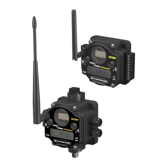
SureCross Performance FlexPower Gateway
For additional information, the most recent version of all documentation, and a complete list of accessories, refer to Banner Engineering's
website, www.bannerengineering.com/surecross.
Models
Frequency
900 MHz ISM
DX80G9M2S-P7
Band
2.4 GHz ISM
DX80G2M2S-P7
Band
WARNING: Not To Be Used for Personnel Protection
Never use this device as a sensing device for personnel protection. Doing so could lead to serious
injury or death. This device does NOT include the self-checking redundant circuitry necessary to allow its
use in personnel safety applications. A sensor failure or malfunction can cause either an energized or de-
energized sensor output condition.
CAUTION: Never Operate 1 Watt Radios Without Antennas
To avoid damaging the radio circuitry, never power up SureCross Performance or SureCross MultiHop (1
Watt) radios without an antenna.
The SureCross® Performance Wireless Network
P/N 155285_web
Rev. D
The SureCross® wireless system is a radio frequency network with integrated I/O that can
operate in most environments and eliminate the need for wiring runs. Wireless networks are
formed around a Gateway, which acts as the wireless network master device, and one or
more Nodes.
• Wireless industrial I/O device with up to 12 sinking discrete inputs or outputs. Default
configuration is set to 6 inputs and 6 outputs (without bit-packing)
• Selectable transmit power levels of 250 mW or 1 Watt and license-free operation up to 4
watt EIRP, with a high-gain antenna, in the U.S. and Canada for 900 MHz
• Power options allow for +10 to 30V dc or solar for low power applications; this model is
not recommended for DX81 or DX81P6 battery-powered operations
• DIP switches for user configuration
• Modbus serial interface
• Site Survey analyzes the network's signal strength and reliability and displays the re-
sults on the Gateway's LCD
• Frequency Hopping Spread Spectrum (FHSS) technology and Time Division Multiple
Access (TDMA) control architecture ensure reliable data delivery within the unlicensed
Industrial, Scientific, and Medical (ISM) band
• Transceivers provide bidirectional communication between the Gateway and Node, in-
cluding fully acknowledged data transmission
• Lost RF links are detected and relevant outputs set to user-defined conditions
Power
+10 to 30V dc or solar power (this model is
not recommended for DX81 or DX81P6 bat-
tery-powered operation)
DX80...C (IP20; NEMA 1) models are also available. To order this model with an IP20 housing, add a C
to the end of the model number: DX80G9M2S-P7C.
I/O
Discrete I/O: Up to 12 sinking inputs or up to 12
NMOS sinking outputs (for a total of 12 I/O)
(Default configuration is 6 IN and 6 OUT, without
bit-packing)
3/14/2013
Advertisement
Table of Contents

Related Manuals for Banner DX80G9M2S-P7


Summary of Contents for Banner DX80G9M2S-P7
- Page 1 • Lost RF links are detected and relevant outputs set to user-defined conditions For additional information, the most recent version of all documentation, and a complete list of accessories, refer to Banner Engineering's website, www.bannerengineering.com/surecross.
-
Page 2: Surecross® Performance Gateways And Nodes
The UCT requires a special USB to RS-485 (model number BWA-UCT-900 for 1 Watt radios, BWA-HW-006 can be used for all other radios) converter cable to pass information between your computer and the Gateway. Download the most recent revisions of the UCT software from Banner Engineering's website: http:// www.bannerengineering.com/wireless. -
Page 3: Configuring The Dip Switches
For additional information, including installation and setup, weatherproofing, device menu maps, troubleshooting, and a list of accesso- ries, refer to one of the following product manuals. • SureCross Quick Start Guide: Banner part number 128185 • SureCross Wireless I/O Network Manual: 132607 •... - Page 4 • Non-Performance radios must be set to use Extended Address Mode (DIP switch 1 ON) For more detailed instructions about setting up your wireless network, refer to the Quick Start Guide, Banner document number 128185. For more information about using Performance and non-Performance radios within the same network, refer the technical note titled Mixing Performance Radios and 150 mW Radios in the Same Networklisted on the FAQ/Knowledgebase section of Banner's Wireless Sensor Networks website.
- Page 5 SureCross Performance FlexPower Gateway Wire No. Wire Color Brown 10 to 30V dc White RS485 / D1 / B / + Blue dc common (GND) Black RS485 / D0 / A / – Gray 3.6 to 5.5V dc Terminal Blocks and Wiring (12 Sinking I/O Models) IOx.
-
Page 6: Led Behavior For The Gateways
SureCross Performance FlexPower Gateway IOx. Input or output (depending on configuration) NC. No connection (Nodes) RX/-. Serial comms line (Gateway and DX85 models) IO10 TX/+. Serial comms line (Gateway and DX85 models) IO11 IO12 V+. Power, 10 to 30V dc power connection. V-. - Page 7 SureCross Performance FlexPower Gateway Modbus Holding Register I/O Type Holding Regis- Terminal Poin I/O Range ter Representa- Block Labels tion Gateway or Any Node Min. Max. Min. Max. DX85 Value Value (Dec.) (Dec.) 10 + (Node# × 16) 11 + (Node# × 16) Non Bit-Packed Discrete OUT (de- 12 + (Node# ×...
-
Page 8: Storage Mode And Sleep Mode
SureCross Performance FlexPower Gateway Defining Inputs and Outputs Using the UCT To configure either a Gateway or Node, select the Gateway or specific Node from the dropdown list. To configure a DX85 Remote I/O model, set the DX85's Slave ID to 01 and select the Gateway from the dropdown list. To define which of the 12 I/O points are inputs for the selected device, adjust the threshold parameter for I/O point 1. - Page 9 SureCross Performance FlexPower Gateway Radio General 900 MHz (1 Watt): 30 dBm conducted (up to 36 dBm 900 MHz Consumption: Maximum current draw is <100 EIRP) mA and typical current draw is <50 mA at 24V dc. (2.4 GHz consumption is less.) 2.4 GHz: 18 dBm conducted, less than or equal to 20 Housing dBm EIRP...
-
Page 10: Antenna Installation
Banner Engineering Corp. warrants its products to be free from defects in material and workmanship for one year following the date of shipment. Banner Engineering Corp. will repair or replace, free of charge, any product of its manufacture which, at the time it is returned to the factory, is found to have been defective during the warranty period.
Need help?
Do you have a question about the DX80G9M2S-P7 and is the answer not in the manual?
Questions and answers