Table of Contents
Advertisement
DOKUMENT TEN JEST PRZEZNACZONY DLA KLIENTÓW FIRMY
DOKUMENT TEN JEST PRZEZNACZONY DLA KLIENTÓW FIRMY
DOKUMENT TEN JEST PRZEZNACZONY DLA KLIENTÓW FIRMY
Internetowy sklep elektroniczny
Internetowy sklep elektroniczny
Tel. Kom. +48 0 888139522
Tel.
Fax. +48 033 48 66617
e-mail
e
WWW.DIOLUT.PL
Kontakt
Tel. +48 033 4866616
diolut@diolut.pl
Advertisement
Table of Contents

Subscribe to Our Youtube Channel
Related Manuals for UNI-T UT30A


Summary of Contents for UNI-T UT30A
- Page 1 DOKUMENT TEN JEST PRZEZNACZONY DLA KLIENTÓW FIRMY DOKUMENT TEN JEST PRZEZNACZONY DLA KLIENTÓW FIRMY DOKUMENT TEN JEST PRZEZNACZONY DLA KLIENTÓW FIRMY Internetowy sklep elektroniczny Internetowy sklep elektroniczny WWW.DIOLUT.PL Kontakt Tel. +48 033 4866616 Tel. Tel. Kom. +48 0 888139522 Fax. +48 033 48 66617 e-mail diolut@diolut.pl...
-
Page 2: Table Of Contents
Model UT30A: OPERATING MANUAL Table of Contents (1) Page Title Overview Unpacking Inspection Safety Information Rules For Safe Operation International Electrical Symbols The Meter structure Make Measurements Measurement Operation DC Voltage Measurement AC Voltage Measurement DC Current Measurement D. AC Current Measurement... - Page 3 Model UT30A: OPERATING MANUAL Table of Contents (2) Title Page Continuity test General Specifications Accuracy Specifications DC Voltage AC Voltage C. DC Current D. AC Current Resistance Diode, Transistor, Continuity Maintenance “Hold”, “Power” Button Fuse and Battery replacement...
-
Page 4: Overview
To avoid electric shock or personal injury, read the "Safety Information" and "Rules for Safe Operation" carefully before using the Meter. UT30A Multimeter is 3 3/4 digits with steady operations, fashionable structure and highly reliable hand-held measuring instrument. The meter can measure DC/AC Voltage, DC/AC Current, Resistance, Diode, Transistor hFE, Continuity,and etc.It... -
Page 5: Unpacking Inspection
Model UT30A: OPERATING MANUAL Unpacking Inspection Open the packing case and take out the Meter. Check the following items carefully to see any missing or damaged part: Item Description Operating Manual 1 piece Test Lead 1 pair Holster (Note: Purchase another protector) 1 piece In the event you find any missing or damage, please contact your dealer immediately. -
Page 6: Safety Information
Model UT30A: OPERATING MANUAL Safety Information The UT30A complies with IEC61010-1: Pollution Degree 2;(CATI600V & CATII 300V voitage standard) with double insulation.Use the Meter only as specified in this msnual.otherwise ,the protection provided by the Meter may be impaired. CAT I-F or local level. telecommunication.electronic with small transient ovltage. -
Page 7: Rules For Safe Operation
Model UT30A: OPERATING MANUAL Rules For Safe Operation (1) Warning Read the manual carefully before use. Use the Meter only as specified in this manual, otherwise, the protection provided by the Meter may be impaired. Do not operate the Meter unless the bottom case has been closed as terminal can carry voltage. - Page 8 Model UT30A: OPERATING MANUAL Rules For Safe Operation (2) to avoid electric shock. l Use only 0.5A/250V φ5X20(mm) fast acting fuse to replace the bad one. Do not operate or store the Meter under high temperature or humid condition, otherwise, the Meter will get worse.
-
Page 9: International Electrical Symbols
Model UT30A: OPERATING MANUAL International Electrical Symbols AC or DC AC Current DC Current Grounding Double Insulated. Deficiency of Built-In Battery Diode. Fuse. Safety Rules Continuity Test Conforms to Standards of European Union. -
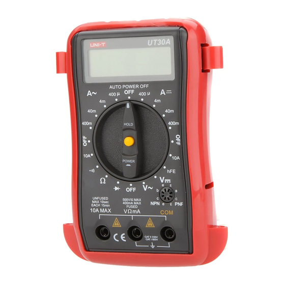
Page 10: The Meter Structure
Model UT30A: OPERATING MANUAL The Meter structure The Meter structure (figure 1) Liquid Crystal Display Data hold or POWER function Button Rotary Switch Transistor Test Jack Common Input Jack 10A Input Jack Ω Input Jack for General Measurement ( figure 1) -
Page 11: Make Measurements
Model UT30A: OPERATING MANUAL Make Measurements First, set rotary switch to proper position, sfter several seconds of self-check, the meter will enter measuring state. when appear on LCD, replace a new battery to ensure accurate display. Second, symbol beside the input jack, warns you... -
Page 12: Measurement Operation
Model UT30A: OPERATING MANUAL Measurement Operation (1) DC Voltage Measurement (figure 2) Warning Never measure voltage value exceeding 500V, although it is possible to get the reading, which will cause damages to the internal circuit and hurt users; black red... - Page 13 Model UT30A: OPERATING MANUAL Measurement Operation (2) 1) Measuring value input from “VΩmA” (red test lead) and “COM” (black test lead.) 2) The Meter has auto-range function with initial range 400mV, at which, the meter may display irregular digits for open Circuit, and come to ZERO for short circuit, which are both normal.
-
Page 14: Ac Voltage Measurement
Model UT30A: OPERATING MANUAL Measurement Operation (3) AC Voltage Measurement: (figure 3) Warning Same as DC voltage measurement, however, The meter has auto-range function with initial range of 4V, and input exceeding 750V would make it clatter with LCD glittering, which warns you should pay extra attention. -
Page 15: Dc Current Measurement
Model UT30A: OPERATING MANUAL Measurement Operation (4) DC Current Measurement (figure 4) Warning This range is manual range. Do not measure, when value between open voltage and earth exceeding safety voltage 60V, to avoid damages to the tested Meter or instrument, and hurt the user. - Page 16 Model UT30A: OPERATING MANUAL Measurement Operation (5) Before measurement, cut off the power of object to be measured and inspect whether input terminal or rotary switch is set to the proper range. Ensure it is proper, then you can measure the object with power on.
-
Page 17: Ac Current Measurement
Model UT30A: OPERATING MANUAL Measurement Operation (6) AC Current Measurement (figure 5) Warning Same as DC current measurement. black red (figure 5) -
Page 18: Resistance Measurement
Model UT30A: OPERATING MANUAL Measurement Operation (7) Resistance Measurement (figure 6) Warning To avoid damages to the Meter, when measuring resistance, cut off the power of the object and no charge in capacitor. 1) Measuring value inputs from “VΩ ”... -
Page 19: Diode Measurement
Model UT30A: OPERATING MANUAL Measurement Operation (8) It will take several seconds for the display to become stabilize when resistance value is over 1MΩ, it is normal, because it is auto-range. F. Diode measurement ( figure 7) Warning Cut off the power supply of the object to avoid damages to the Meter When measuring diode, no charge in capacitor. -
Page 20: Transistor Hfe Measurement
Model UT30A: OPERATING MANUAL Measurement Operation (9) open circuit; at this time, the red test lead is positive pole, and the black one is negative pole. In addition, “V” acts as unit of this range. G. Transistor hFE Measurement ( figure 8) 1) Check that the transistor is PNP or NPN type at first. -
Page 21: Continuity Test
Model UT30A: OPERATING MANUAL Measurement Operation (10) H. Continuity test (figure9) Warning Before testing continuity, power off and no charge in capacitor to avoid damages to the Meter. Measuring value inputs from “VΩ mA” jack (red test lead) and “COM” jack (black test lead). -
Page 22: General Specifications
Model UT30A: OPERATING MANUAL General Specifications (1) The maximum voltage, between any terminal and earth, is 500Vrms. The “COM” input terminal is always connected with the black Test lead. The “V,Ω,mA” input terminal is always connected with the red test lead and is used to measure voltage up to 500V, resistance, and current up to 400mA. - Page 23 Model UT30A: OPERATING MANUAL General Specifications (2) Type 2pieces of Battery Deficiency...
-
Page 24: Accuracy Specifications
Model UT30A: OPERATING MANUAL Accuracy Specifications (1) Accuracy: (a% reading + b digits), which guarantee for one year. Operating Temperature:23 Relative Humidity: <75% Temperature coefficient: 0.1 (specified accuracy)/1 DC Voltage Resolution Range Accuracy (0.8%+3) 400mV 0.1mV 10mV (0.8%+1) 400V 100mV... -
Page 25: Ac Voltage
Model UT30A: OPERATING MANUAL Accuracy Specifications (2) AC Voltage Range Resolution Accuracy 10mV (1.2%+3) 400V 100mV 500V Remark: Input Impedance: 10MΩ Frequency: 40-400Hz Display: RMS of Sine Wave Value (Average Value) Overload protection: 500V (AC or DC) -
Page 26: Dc Current
Model UT30A: OPERATING MANUAL Accuracy Specifications (3) DC Current Range Resolution Accuracy 400µA 0.1µA 1µA (1%+2) 40mA 10µA (1.2%+2) 400mA 100µA (1.5%+2) 10mA Remark: Overload Protection: 0.5A/250v fuse. Un-fuse at 10A, measuring time limit is equal or less than 10 seconds, and time interval should be equal or over 15 minutes. -
Page 27: Ac Current
Model UT30A: OPERATING MANUAL Accuracy Specifications (4) AC Current Range Resolution Accuracy 400µA 0.1µA 1µA (1.3%+5) 40mA 10µA 400mA 100µA (2%+5) 10mA Remark: Overload Protection: 0.5A/250V fuse; Un-fuse at 10A; measuring time limit is equal to or less than 10 seconds; time interval is equal or over 15 minutes. -
Page 28: Resistance
Model UT30A: OPERATING MANUAL Accuracy Specifications (5) Resistance Range Resolution Accuracy (1.2%+2) 400Ω 0.1Ω 4kΩ 1Ω 10Ω 40kΩ (1%+2) 400kΩ 100Ω (1.2%+2) 1KΩ 4MΩ (1.5%+2) 40MΩ 10KΩ Remark: Overload Protection: All ranges are 230V (DC/ AC current). -
Page 29: Diode, Transistor, Continuity
Model UT30A: OPERATING MANUAL Accuracy Specifications (6) Diode, Transistor, Continuity Test Input Range Resolution Function Remark Protection 3V when open circuit 230V DC Diode or AC 10µA Vce Transistor 1β The buzzer beeps Continuity 230V DC Beeper when the value is less 0.1Ω... -
Page 30: Maintenance
Model UT30A: OPERATING MANUAL Maintenance (1) “Hold”, “Power” Button Function 1) Pressing “Hold” button holds current reding displayed on LCD in open state,press current reading displayed on LCD it again to release the At power on state,press Hold to enter and exit the touch hold mode At hold mode,it can capture the present reading and display on the LCD, otherwise,the reading is a random value. -
Page 31: Fuse And Battery Replacement
Model UT30A: OPERATING MANUAL Maintenance (2) B. Fuse and Battery replacement (figure 10) Remove inputs & test leads from terminals. Remove two rubber feet and two screws from the bottom case. Separate the case bottom from the case top. Replace the battery or fuse as per the following specification: Battery: 1.5V(AAA) NEDA 1604 or 6F22 or... - Page 32 Model UT30A: OPERATING MANUAL ~ END ~ * The manual is subject to changes without separate notice. *...
- Page 33 Model UT30A: OPERATING MANUAL Copyright 2001 Uni-Trend International Limited. All rights reserved. Manufacturer: UNI-TREND TECHNOLOGY(DONG GUAN)LIMITED Address: Dong Fang Da Dao, Bei Shan Dong Fang Industrial Development District, Hu Men Town, Dong Guan City, Guang Dong Province, China Headquarters: Uni-Trend International Limited...
Need help?
Do you have a question about the UT30A and is the answer not in the manual?
Questions and answers