
Subscribe to Our Youtube Channel
Related Manuals for UNI-T UTL8500X Series


Summary of Contents for UNI-T UTL8500X Series
- Page 1 Programable DC Electronic Load User Manual UTL8500X Series Programable DC Electronic Load User Manual...
-
Page 2: Table Of Contents Preface
UNI-T or an authorized UNI-T distributor. Power cords, accessories and fuses, etc. are not included in this warranty. If the product is proved to be defective within the warranty period, UNI-T reserves the rights to either repair the defective product without charging of parts and labor, or exchange the defected product to a working equivalent product (determined by UNI-T). -
Page 3: Guarantee Limit
This warranty is written by UNI-T for this product and it is used to substitute any other express or implied warranties. UNI-T and its distributors do not offer any implied warranties for merchantability or applicability purposes. - Page 4 Use the correct power cord Only use the dedicated UNI-T power cord to connect the measured power supply and the electronic load to ensure that there is no overheat by short-circuit current, otherwise electric shock may occur.
- Page 5 Programable DC Electronic Load User Manual Safety symbols Direct and alternating Direct current Alternating current current Three phase Grounding Protective grounding Signal Danger Warning grounding Neutral wire Live wire On (Power) or central wire Ground Terminal for Off (Power) Backup power Chassis Environment-Friendly Use Period (EFUP) This product contains certain hazardous substances and...
-
Page 6: Table Of Contents
Programable DC Electronic Load User Manual Table of Contents Preface ..........................2 Copyright Information ......................2 Warranty Service ......................... 2 Guarantee Limit ........................3 Safety Information ........................ 3 1. Product Overview ......................9 1.1 Product Series ......................9 1.1.1 Features ....................... 9 1.2 Front Panel ...................... - Page 7 Programable DC Electronic Load User Manual 4.3.3 Ripple Measurement .................. 41 4.3.4 Input Control ....................42 4.4 Waveform ......................42 4.5 Trigger Method ..................... 43 4.6 Sense ........................43 4.7 Screenshot ......................43 4.8 Saving and Applying of Configuration ..............44 5.
- Page 8 Programable DC Electronic Load User Manual 7.3 Remote Compensation Terminal ................69 7.4 Trigger Signal Terminal ..................70 8. Technical Specifications ....................71...
-
Page 9: Product Overview
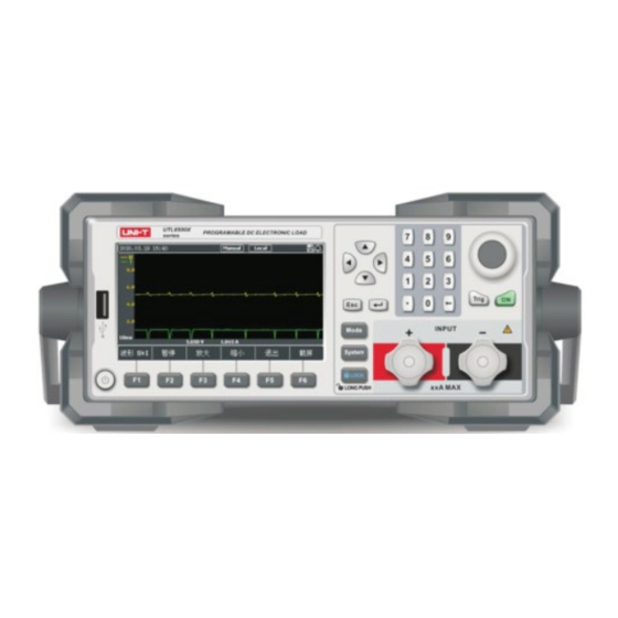
0~15A 0~150W UTL8500X series DC electronic load comes with 4.3-inch LCD screen, wide power range and up to 0.1mV/0.1mA resolution. It supports multiple test modes: dynamic test, overload test, auto test, list test, battery test and CR-LED test, etc. The instrument is a great tool in areas of electronic performance test, battery set test, power supply test, new energy test, aerospace industries, high-power test, labs, R&D and production line, etc. -
Page 10: Front Panel
Programable DC Electronic Load User Manual The list mode comes with storage function, and supports the saving and applying of the external U disk and the upgrade of the U disk system. Screenshot function with list storage & recall ... - Page 11 Programable DC Electronic Load User Manual Direction keys: They are used to move cursor or adjust the ⑤ selected value. F1-F6 function keys: They are used to perform the function ⑥ displayed on the screen. Input terminals: They are used to connect power source. Please ⑦...
-
Page 12: Rear Panel
Programable DC Electronic Load User Manual 1-2-3. It is the male end of the quick-charging connector. These 4 pins are used to connect the 4 terminal holes of the female end of the quick-charging test board 7-Middle assembly, as shown in Figure 1-2-3. Note: This jack socket has a fool-proof design. -
Page 13: Inspection And Installation
Programable DC Electronic Load User Manual ③ Trigger signal terminal Please refer to part 7.2 for details. AC220/110V transfer switch Voltage scale switch of AC power source ④ External communication interface to realize ⑤ RS232 interface the remote control with the load ⑥... -
Page 14: Requirements Of Power Supply
250V/0.5A fuse when 110V AC power is input. 2.3 Operating Environment UTL8500X series can only be used in common-temperature and low-condensing zone. The general environment requirements are listed as follows. During the on-load process, the speed of the cooling fan will adjust based on the change of the cooling fin’s temperature. -
Page 15: Cleaning
Programable DC Electronic Load User Manual Storage temperature -10°C~60°C Altitude ≤2000m Degree of pollution 2.4 Cleaning To avoid electric shock, please unplug the power cord before cleaning. Clean the housing and the panel with a soft damp cloth, and make sure it is completely dry. -
Page 16: Measurement Display Interface
Programable DC Electronic Load User Manual 3. Measurement Display Interface Power on and Run ● Introduction of Screen Display ● 3.1 Install Load Connection Wire The electronic load is connected to the tested object through the "+" and "-" terminals on the front panel. -
Page 17: Introduction Of Screen Display
Programable DC Electronic Load User Manual Warning: Please make sure that the power supply voltage is consistent with the supply voltage before turning on the power, otherwise the instrument will be burnt out. Please be sure to connect the main power plug to a power socket with ground protection. Do not use a wiring board without ground protection. -
Page 18: Running Indicator
In pause status 3.3.3 Running Indicator UTL8500X series electronic load comes with running indicator on the ON button. In on-load mode, the indicator will light up, indicating that the load is in a loaded status. Pressing the ON button again can stop loading and the indicator will go out. -
Page 19: Constant State Test Modes
Programable DC Electronic Load User Manual 4.1 Constant State Test Modes There are four types of constant state test modes: constant current (CC), constant voltage (CV), constant resistance (CR) and constant power (CP). In the initialization interface, users can select [Mode] by pressing the soft key at the bottom of the screen, and then press [CC], [CV], [CR], [CP] to enter the corresponding mode. -
Page 20: Constant Voltage Test
Programable DC Electronic Load User Manual Figure 4-1-1-1 Setting Interface of CC Mode Operation steps: 1. In initial interface, select [Mode], and then press [CC] to enter the setting interface of <Constant Current CC>. 2. Move the cursor to current setting by pulse knob, and press the Enter button change the current value (the value changes from yellow to white) by keyboard or pulse knob. -
Page 21: Constant Resistance Test
Programable DC Electronic Load User Manual Figure 4-1-2-1 Setting Interface of CV Mode Operation steps: 1. In initial interface, select [Mode], and then press [CV] to enter the setting interface of <Constant Voltage CV>. 2. Move the cursor to voltage setting by pulse knob, and press the Enter button change the voltage value (the value changes from yellow to white) by keyboard or pulse knob. -
Page 22: Constant Power Test
Programable DC Electronic Load User Manual Figure 4-1-3-1 Setting Interface of CR Mode Operation steps: 1. In initial interface, select [Mode], and then press [CR] to enter the setting interface of <Constant Resistance CR>. 2. Move the cursor to resistance setting by pulse knob, and press the Enter button to change the resistance value (the value changes from yellow to white) by keyboard or pulse knob. -
Page 23: More Modes
Constant power Figure 4-1-4-2 Relationship of Voltage and Current in CP Mode 4.2 More Modes To meet various test requirements, UTL8500X series electronic load offers more test modes for choice, including Dynamic, List, Dual, OCP/OPP, CR-LED, Battery, Load Effect,... -
Page 24: Dynamic Mode
4.2.1 Dynamic Mode UTL8500X series electronic load has two dynamic loading modes: CC and CV. In the dynamic mode, users can set two fixed-value parameters for corresponding constant state... - Page 25 Programable DC Electronic Load User Manual modes. Through the set operation mode, the load is switched back and forth between the two values. Figure 4-2-1-1 Interface of Dynamic Mode Parameters of dynamic mode: Dynamic test Description of parameters Mode Dynamic on-load mode: CC/CV Continues: The load will automatically and continuously switch between two set high/low values till the operation reaches the set repeating times, and then the test ends.
-
Page 26: List Mode
Programable DC Electronic Load User Manual Upper value Fall slope Rise slope Lower value Upper duration Lower duration One cycle Figure 4-2-1-2 Dynamic Mode Operation steps: 1. In initial interface, select [Mode], and then press [Dynamic] to enter the setting interface of <Dynamic Mode>. - Page 27 Programable DC Electronic Load User Manual Figure 4-2-2 Setting Interface of List Mode List value Description Select the fast charge charger protocol supported QC2.0/QC3.0/QC4.0 by the tested power supply. Protocol BC1.2 and Protocol /PD3.0/BC1.2 single mode DPDN are the same function. (UTL8511C) The fast charge charger supports different Set the voltage point...
- Page 28 Programable DC Electronic Load User Manual List mode Parameters Description Set the group number of the list test Group 1~60 parameters for easy calling. Step 1~16 Set the step of the list test. Set the number of repetitions of each Repeat 0~99999 measurement in the current mode.
- Page 29 Programable DC Electronic Load User Manual Continues: The load will continue to the next step after executing one step until the end of the operation. Trig: The load will pause after executing a step, and wait for the trigger signal before continuing to the next step.
-
Page 30: Dual Mode
Programable DC Electronic Load User Manual Figure 4-2-2-2 Test Page of List Mode 7. Press the ON button, the electronic load starts to load, and the indicator light below the button lights up. If users want to suspend the test, they can press the [Pause] button. If they need to stop the load, press the ON button again, and the running indicator light goes out. - Page 31 Programable DC Electronic Load User Manual Figure 4-2-3-1 Interface of Dual Mode Parameter setting in dual mode: Parameter Description Mode CR+CC/CV+CR/CV+CC Start value Set the start value of the dual mode Swap value Set the swap value of the dual mode To use the dual mode, first select the needed mode, and then set the fixed values of the two corresponding modes.
-
Page 32: Ocp/Opp Mode
4.2.4 OCP/OPP Mode This mode is used to detect the protection function of the tested power supply under overload conditions. UTL8500X series electronic load has two test modes: OCP/OPP. Figure 4-2-4-1 Interface of OCP/OPP Mode Parameter setting in OCP/OPP mode:... -
Page 33: Cr-Led Mode
Programable DC Electronic Load User Manual Start current Step current Step time Figure 4-2-4-2 OCP/OPP Mode Description of OCP/OPP mode: Since OCP/OPP mode will continuously increase the output power of the tested object, please input reasonable load parameters during the test to avoid damage to the tested object. -
Page 34: Battery Mode
Programable DC Electronic Load User Manual truly simulated, so that the test voltage and current are between a normal and stable value, avoiding oscillations and other unstable conditions produced by constant resistor discharge, so as to better check the actual loading of the LED drive power supply. Figure 4-2-5-1 Interface of CR-LED Mode Parameter setting in CR-LED mode: Parameter... - Page 35 Programable DC Electronic Load User Manual the curve of battery discharge. Figure 4-2-6-1 Interface of Battery Mode Parameter setting in battery mode: Parameter Description Mode Battery discharge mode: CC/CR/CP Load value Set loading value Stop voltage Set the lower limit voltage of stopping discharge In the battery mode, select any discharge mode as needed, and set the load parameters and stop voltage of this mode.
-
Page 36: Load Effect
Programable DC Electronic Load User Manual interface. Move the cursor to the needed setting position by pulse knob, and press the Enter button to change the parameter (the parameter changes from yellow to white) by keyboard or pulse knob. Press the Enter button again to confirm. -
Page 37: Ovp Mode
Programable DC Electronic Load User Manual and the values of △V and Reg will be detected. During the test, the ON button can be used to control the load switch. Operation steps: In initial interface, select [Mode], [More], [More], and then press [Load Effect] to enter the setting interface. -
Page 38: Short-Circuit Mode
Programable DC Electronic Load User Manual edge of the voltage, it starts timing and triggers at the set trigger voltage. The load records the voltage at the peak point, and calculates the time from the peak point to the trigger point. -
Page 39: Time Mode
Programable DC Electronic Load User Manual When the set short-circuit time is reached (refer to chapter 6.2 for the short-circuit time setting), the electronic load returns to the original working status. The actual current value consumed by the electronic load in the short-circuit mode depends on the current load working mode and current range. - Page 40 Programable DC Electronic Load User Manual Figure 4-2-10-1 Interface of Time Mode Parameter setting in time mode: Parameter Description Mode Set the load mode (CC/CV/CR/CP/Open) Value Set the load value of the current mode Start trigger Set the start condition (voltage/current/external) End trigger Set the end condition (voltage/current/external) Start edge...
-
Page 41: Parameter Input And Loading Measurement
4.3.3 Ripple Measurement UTL8500X series electronic load supports voltage ripple (Vpp) and current ripple (lpp) measurement and real-time display. In the test interface, users can see these parameters: Vpp/Vp+/Vp-, lpp/lp+/lp-, and can alternately view the required parameters by using the "Page"... -
Page 42: Input Control
LCD screen. 4.4 Waveform The UTL8500X series electronic load has a waveform display function. Users can view the voltage and current waveforms by pressing the function key [Waveform], as shown in Figure 4-4. -
Page 43: Trigger Method
Programable DC Electronic Load User Manual 4.5 Trigger Method When using Dynamic, List or Time mode, the trigger function of the electronic load may be used. Users can choose manual trigger (Manual) or external trigger (External). Operation steps: In the Dynamic, List or Time mode page, users can quickly modify the trigger mode by selecting [Trigger] through the function keys at the bottom of the screen, and the words "Manual"... -
Page 44: Saving And Applying Of Configuration
Programable DC Electronic Load User Manual it and display the USB symbol on the upper right corner of the screen, indicating that the U disk has been connected to the device. When users need to use the screenshot function, press the [Print Sc] button, and the load will save the current screen image to the U disk. - Page 45 Programable DC Electronic Load User Manual turned on), press the soft key [QC2.0] at the bottom of the screen to enter the <QC2.0> display interface. If it is not on the main measurement interface , users can press the button [Mode], then select the soft key [Fast Charge] to enter the fast charge horizontal bar selection interface, and finally enter the <QC2.0>...
- Page 46 Programable DC Electronic Load User Manual (5V/9V/12V/20V voltage can be set). Then press key to enter the voltage setting area, use the knob and up/down keys to select the voltage to be triggered, and press the enter key to trigger. If the trigger is successful, the voltage display value will change accordingly, and then press the ON button on the panel to load.
-
Page 47: Qc3.0 Test
Programable DC Electronic Load User Manual 5-1-2, it is the 7.500V load success interface (the maximum value of Vset in the left box should be slightly less than 9V to load successfully). In the test operating interface, users can see the operating process and result data, such as Time, Vpp, etc. - Page 48 Programable DC Electronic Load User Manual QC3.0 test interface setting steps: After entering the setting interface, press the soft key [Setting Switch] to switch the selected box to carry out load setting or fast charge setting. If users select the left box, they can input the load value with the keyboard, press the Enter key to confirm the input value, and then press the ON button on the panel.
-
Page 49: Qc4.0 Test
Programable DC Electronic Load User Manual the ON indicator light turns green at this time. Then use the arrow keys to select [ON/OFF] on the screen, and press the Enter key to start or stop. After the startup is successful, the [ON/OFF] on the screen is displayed in red, and the indicator light at the top right of the screen is displayed in red during operation, and turns to white after the operation is over. - Page 50 Programable DC Electronic Load User Manual handshake with the measured object: During the handshake/operating process, the indicator at the top right of the screen is red, otherwise it is white. If the handshake is successful, the status will be displayed as [OK], as shown in the upper right corner of Figure 5-3, otherwise it will be displayed as [Err].
- Page 51 Programable DC Electronic Load User Manual exceed the specification range of the loaded object and need to be reset. The step test function is used to test the performance of the object under test by continuously triggering different voltage points in automatic/manual mode. The parameters that can be set include: start voltage, step voltage, step time, end voltage, and step mode.
-
Page 52: Pd2.0/3.0 Test
Programable DC Electronic Load User Manual 5.4 PD2.0/3.0 Test Steps to enter the PD2.0/3.0 test interface: Press the power button to turn on the electronic load. In the main measurement interface (the default main measurement interface is CC mode when the instrument is turned on), press the soft key [PD3.0] at the bottom of the screen to enter the <PD2.0/3.0>... - Page 53 Programable DC Electronic Load User Manual Figure 5-4-2 <PD2.0/3.0> Setting and Display Interface PD2.0/3.0 test interface setting steps: After entering the setting interface, press the soft key [Setting Switch] to switch the selected box to carry out load setting or fast charge setting. If users select the left box, they can input the load value with the keyboard, press the Enter key to confirm the input value, and then press the ON button on the...
-
Page 54: Pe2.0 Test
Programable DC Electronic Load User Manual the ON button on the panel to load. After the load is successful, the ON button indicator will turn green, the correct voltage and load value will be displayed on the screen, and the OK symbol will be displayed on the upper right of the screen. Figure 5-4-2 shows the page after PPS 9V/1.000A is loaded. - Page 55 Programable DC Electronic Load User Manual Figure 5-5 <PE2.0> Setting and Display Interface PE2.0 test interface setting steps: After entering the setting interface, press the soft key [Setting Switch] to switch the selected box to carry out load setting or fast charge setting. If users select the left box, they can input the load value with the keyboard, press the Enter key to confirm the input value, and then press the ON button on the...
-
Page 56: Dpdn Test
Programable DC Electronic Load User Manual fixed value settings (such as Vset, Rset or Pset). After setting and entering the test, press the ON button on the panel to load. Please refer to chapter 5.1 step 4 for details. In the test operating interface, users can see the operating process and result data, such as Time, Vpp, etc. - Page 57 Programable DC Electronic Load User Manual Figure 5-6 <DPDN> Setting and Display Interface DPDN test interface setting steps: After entering the setting interface, press the soft key [Setting Switch] to switch the selected box to carry out load setting or fast charge setting. If users select the left box, they can input the load value with the keyboard, press the Enter key to confirm the input value, and then press the ON button on the...
-
Page 58: Fast Charge Setting
Programable DC Electronic Load User Manual charge mode and return to the main measurement interface. Note: The measured object needs to allow the external device to control the voltage of the D+ and D- data leads; otherwise the measured object may be damaged. 5.7 Fast Charge Setting Press the [System] key to enter the <System Configuration>... -
Page 59: System Configuration Page
Programable DC Electronic Load User Manual PD trigger delay Set the waiting time before initializing PD power CC channel detection Check whether the CC1 and CC2 leads are connected well 6. System Configuration Page System Configuration ● Parameter Setting ● File ●... -
Page 60: Language
Programable DC Electronic Load User Manual Key sound ON/OFF Whether to enable key sound Date Year/Month/Day Set system date Whether to enable warn Warn sound ON/OFF sound Time Hour/Minute/Second| Set system time Adjust the screen brightness, DIM display 1~5 levels of brightness 5 levels Default: boot into the constant current (CC) interface... -
Page 61: Date
6.1.4 Warn Sound The UTL8500X series electronic load has warn sound function. When the load ends or encounters an abnormal problem during the test, the electronic load will emit a warn sound through the built-in buzzer. When the test is successful, the load will emit two short beeps. -
Page 62: Knob Active
Programable DC Electronic Load User Manual 6.1.8 Knob Active This option is used to make the current adjustment by the knob take effect immediately. It is on by default, that is, every time you rotate the knob to change the parameter in CC, CV, CR, CP mode, it will take effect immediately. -
Page 63: Parameter Setting
Programable DC Electronic Load User Manual 6.2 Parameter Setting Users can enter the system configuration interface by pressing the [System] key, and select [Para Set] at the bottom of the screen can enter the <PARAMETER SETTING> page, as shown in Figure 6-2. The parameter setting is used to set the operating parameters and protection parameters of the system. -
Page 64: Run Time
Programable DC Electronic Load User Manual Table 6-2 Description of Parameter Setting (UTL8512S) Parameter setting Setting range Description Run time 0~99999s Set the time for scheduled unload Delay on 0~9999s Set the start time of delay Short time 0.1~99999ms Set the time for short circuit test Set the voltage value of over-voltage V limit 0~150V... -
Page 65: Delay On
Programable DC Electronic Load User Manual 6.2.2 Delay On If users set the delay before the electronic load is loaded each time, no matter what mode it is running, when the ON button is pressed, the electronic load will wait for the set delay time and then start loading. -
Page 66: Vpp Limit
Programable DC Electronic Load User Manual current high speed. High-speed sampling is performed at 300kHz, and medium-speed sampling is performed at 20kHz. 6.2.7 VPP Limit Adjust the protection value of the ripple voltage. When the ripple voltage exceeds the set value, the pop-up window prompts that the ripple exceeds the limit and stop loading. -
Page 67: Instrument Info
Programable DC Electronic Load User Manual Figure 6-3 File Page Save: The device has two storage methods (U disk/internal Flash). Users can view the files stored in the two paths. The screenshots can only be saved to the U disk and cannot be viewed on the electronic load. -
Page 68: Communication Interface And Terminal
● 7.1 RS-232C UTL8500X series electronic load is equipped with RS-232C communication interface according to standards. Users can use the corresponding communication lead for remote operation if they need. There is a DB9 female interface at the end of the electronic load, which can be connected to the computer COM port by using a standard RS-232C cable. -
Page 69: Current Monitor (I Monitor)
When the load consumes a large current, a voltage drop will be generated on the connection lead between the instrument under test and the load terminal. In order to ensure the measurement accuracy, the UTL8500X series electronic load provides a remote measurement terminal on the rear panel. Users can use this terminal to measure... - Page 70 Programable DC Electronic Load User Manual Front panel-input terminal Object under test Rear panel-measurement terminal Figure 7-3 Wiring Diagram of Remote Compensation SE+ and SE- are remote input terminals. In order to avoid the voltage drop caused by too long load input leads, remote test allows to measure directly on the input terminal source to improve measurement accuracy.
- Page 71 Programable DC Electronic Load User Manual 2. Wiring method for active trigger input (external power signal) 3. Wiring method for test result output (need external power supply) Note: 1) The voltage range of all external power supplies shall not exceed DC5V~DC24V. 2) The maximum withstand current of the test result output terminals (④...
- Page 72 Programable DC Electronic Load User Manual Table 8-1 Main technical parameters of UTL8500X series electronic load Model UTL8511S UTL8512S UTL8511C Input v alue 0~150V 0~150V 0~150V Input c urrent 0~3A 0~30A 0~3A 0~30A 0~3A 0~15A Rat ed v alue Input power...
- Page 73 Programable DC Electronic Load User Manual ≥1.05 times the set value, delay ≥1.05 times the set value, delay ≥1.05 times the set value, delay protection protection protection ≥1.1 times the set value, ≥1.1 times the set value, ≥1.1 times the set value, immediate Ov er power prot ec t ion immediate protection immediate protection...
Need help?
Do you have a question about the UTL8500X Series and is the answer not in the manual?
Questions and answers