Table of Contents
Advertisement
Quick Links
Advertisement
Table of Contents

Related Manuals for UNI-T UT118C


Summary of Contents for UNI-T UT118C
- Page 1 UT118C User Manual UT118C Pen type meter User Manual 1 / 18...
-
Page 2: Limited Warranty And Liability
UT118C User Manual Preface Thank you for purchasing this brand new product. In order to use this product safely and correctly, please read this manual thoroughly, especially the Safety Instructions part. After reading this manual, it is recommended to keep the manual at an easily accessible place, preferably close to the device, for future reference. - Page 3 UT118C User Manual 1. Overview UT118C is a 6000-Count True-RMS multimeter with high reliability and safety. It can be used in narrow and dark environments and concentrated circuits by virtue of its compact shape, flashlight and ultra-sharp probe tip. UT118C is designed with full-scale overload protection and unique appearance, making it a new-generation measurement meter with more practical performances.
-
Page 4: Safety Information
UT118C User Manual 4. Safety Information Please note the “Warning Labels and Sentences”. A Warning identifies conditions or actions that pose hazard to the user, and that may damage the Meter or the equipment under test. The Meter complies with IEC/EN61010-1, 61010-2-033, 61010-031,Electromagnetic Radiation EN61326-1 Safety Standard, Basic Insulation, Overvoltage CAT III 600 V and CAT IV 300 V, Pollution Degree 2, and Indoor Use. -
Page 5: Electrical Symbols
UT118C User Manual 5. Electrical Symbols Low battery Battery Alternating current Direct current Both direct and alternating current Warning Caution, possibility of electric shock Grounding It is applicable to test and measuring circuits connected directly to utilization CAT II points (socket outlets and similar points) of the low-voltage MAINS installation. -
Page 6: External Structure
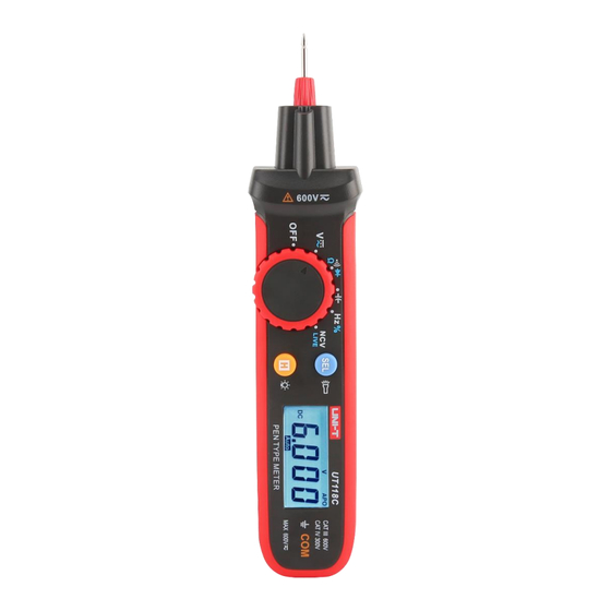
UT118C User Manual 7. External Structure Figure 1 V-end probe Probe cap Flashlight Finger guard Rotary switch Functional buttons LCD display COM terminal Test probe holder 10) Battery cover 11) Test lead slot 6 / 18... -
Page 7: Lcd Display
UT118C User Manual 8. LCD Display Symbol Description TRMS True RMS Low battery Hazardous voltage Alternating-current measurement ━ Negative reading Direct-current measurement Continuity measurement Diode measurement Data hold AUTO Auto range Scan Automatic identification of scanning LIVE LIVE wire identification... -
Page 8: Button Descriptions
UT118C User Manual 10. Button Descriptions Short press: Press the button for 2s Long press: Press the button for ≥2s 1) DCV/ACV position: Short press to cycle through DCV and ACV. 2) Continuity/Resistance/Diode: Short press to cycle through continuity, resistance and diode. - Page 9 UT118C User Manual 11.1 Measure DC/AC Voltage (Figure 3) 1) Set the rotary switch to the DC/AC voltage measurement position. 2) The measurement position is DC voltage position by default. To measure AC voltage, please short press the “SEL” button to switch to AC voltage position.
- Page 10 UT118C User Manual 11.2 Measure Continuity, Resistance and Diode (Figure 4) 1) Set the rotary switch to the continuity/resistance/diode measurement position. 2) By default, the measurement position is the automatic identification mode (in which the Meter can automatically identify the continuity, resistance and diode measurements). By short pressing the “SEL”...
- Page 11 UT118C User Manual * The buzzer will make a long beep if the resistance between both ends of the measured object is ≤10Ω. * “OL” will appear on the LCD if the measured resistor is open or the measured resistance exceeds the maximum range.
- Page 12 UT118C User Manual Warning: * Please discharge the capacitor completely before measurement (especially for capacitor with high voltage) to avoid product damage or personal injury. * When there is no input, the Meter may display a fixed reading, which is the intrinsic compensation capacitance of the Meter.
- Page 13 UT118C User Manual * Disconnect the test lead with the measured circuit after all measurement operations are completed. 11.5 Non-Contact AC Voltage Detection (NCV)/LIVE Wire Identification Operating steps for non-contact AC voltage detection (Figure 7): 1) Set the rotary switch to the NCV/LIVE position.
-
Page 14: Other Functions
UT118C User Manual voltage is present at the insulated/shield conductor only by the detection result. * Please hold the Meter case by hand when performing NCV detection. * If the measured voltage is ≥100V AC, please observe if the measured conductor is insulated to avoid personal injury. - Page 15 UT118C User Manual * Range to ensure accuracy: 5%~100% of range * Residual reading under short-circuit condition: ≤2 counts * “OL” is displayed if the measurement value is ≥620.0V. * Overload protection: 600Vrms (DC/AC) 13.2 AC Voltage Range Resolution Accuracy 6.000V...
- Page 16 UT118C User Manual * Overload protection: 600Vrms (DC/AC) 13.5 Diode Range Resolution Accuracy 6.000 V 0.001 V ±(0.5%+10) * Open-circuit voltage: About 3V * “OL” is displayed if the measurement value is >3.000V. * Overload protection: 600Vrms (DC/AC) 13.6 Capacitance...
-
Page 17: Maintenance
UT118C User Manual * Range to ensure accuracy: 10%~90% of range * Frequency range: 10Hz~10kHz * Input amplitude: 250mVrms ≤ Input amplitude ≤ 20Vrms * Zero-cross waveform * Overload protection: 600Vrms (DC/AC) 13.9 NCV/LIVE Range 45~600V LIVE >100 V (mains voltage) - Page 18 UT118C User Manual 18 / 18...
Need help?
Do you have a question about the UT118C and is the answer not in the manual?
Questions and answers