Table of Contents
Advertisement
Quick Links
Advertisement
Chapters
Table of Contents

Related Manuals for Emerson PACSystems RSTi


Summary of Contents for Emerson PACSystems RSTi
- Page 1 USER MANUAL GFK-2745C Nov 2019 PACSystems RSTi USER MANUAL...
-
Page 2: Table Of Contents
User Manual Contents GFK-2745C Nov 2019 Contents Chapter 1: Introduction ............1 I/O Station Capacity ..................... 2 Installation ......................2 Features ......................2 IOGuidePro Tool ....................3 List of RSTi Modules ..................... 3 1.5.1 Power Modules ..................3 1.5.2 Discrete Inputs ..................3 1.5.3 Discrete Outputs .................. - Page 3 User Manual Contents GFK-2745C Nov 2019 3.2.3 Example ....................16 ST-7111......................17 3.3.1 Interface and Data ................... 17 3.3.2 Specification ................... 18 3.3.3 Example ....................18 ST-7118......................19 3.4.1 Interface and Data ................... 19 3.4.2 Specification ................... 20 3.4.3 Example ....................20 ST-7188......................
- Page 4 User Manual Contents GFK-2745C Nov 2019 3.12 ST-7641......................36 3.12.1 Interface and Data ................... 36 3.12.2 Specification ................... 37 3.12.3 Example ....................37 3.13 Dimension ......................38 3.13.1 ST-7xxx ....................38 3.14 Diagnostics ....................... 38 3.14.1 Normal Module ..................38 Chapter 4: Discrete Inputs .............
- Page 5 User Manual Contents GFK-2745C Nov 2019 4.10.1 Interface and Data ................... 57 4.10.2 Specification ................... 58 4.11 ST-1324......................59 4.11.1 Interface and Data ................... 59 4.11.2 Specification ................... 60 4.12 ST-1804......................61 4.12.1 Interface and Data ................... 61 4.12.2 Specification ................... 62 4.13 ST-1904......................
- Page 6 User Manual Contents GFK-2745C Nov 2019 ST-2424......................78 5.6.1 Interface and Data ................... 78 5.6.2 Specification ................... 79 ST-2514......................80 5.7.1 Interface and Data ................... 80 5.7.2 Specification ................... 81 ST-2524......................82 5.8.1 Interface and Data ................... 82 5.8.2 Specification ................... 83 ST-2318......................
- Page 7 User Manual Contents GFK-2745C Nov 2019 5.18.1 ST-2742, ST-2852.................. 101 5.18.2 ST-2xx4 ....................101 5.18.3 ST-2xx8 ....................101 5.18.4 ST-2xxF ....................102 Chapter 6: Analog Input ............103 ST-3114......................103 6.1.1 The Interface and Data ................103 6.1.2 Specification ..................104 ST-3118......................
- Page 8 User Manual Contents GFK-2745C Nov 2019 6.11.1 Interface and Data ................. 123 6.11.2 Specification ..................124 6.12 ST-3624......................125 6.12.1 Interface and Data ................. 125 6.12.2 Specification ..................126 6.13 ST-3644......................127 6.13.1 Interface and Data ................. 127 6.13.2 Specification ..................128 6.14 ST-3702......................
- Page 9 User Manual Contents GFK-2745C Nov 2019 6.21.7 ST-3808 ....................150 6.22 Current and Voltage Mode ................152 6.22.1 ST-3114 and ST-3118 ................152 6.22.2 ST-3134 ....................152 6.22.3 ST-3214 ....................153 6.22.4 ST-3218 ....................153 6.22.5 ST-3234 ....................154 6.22.6 ST-3424, ST-3428.................. 154 6.22.7 ST-3444 ....................
- Page 10 User Manual Contents GFK-2745C Nov 2019 7.6.1 Interface and Data ................. 172 7.6.2 Specification ..................173 ST-4491......................174 7.7.1 Interface and Data ................. 174 7.7.2 Specification ..................175 ST-4522......................176 7.8.1 Interface and Data ................. 176 7.8.2 Specification ..................177 ST-4622......................
- Page 11 User Manual Contents GFK-2745C Nov 2019 8.1.3 ST-5112 ....................195 8.1.4 ST-5114 ....................197 8.1.5 Dimensions of ST-5101, ST-5111, ST-5112, and ST-5114 ...... 199 8.1.6 Configuration and Operational Function..........199 Serial Module....................220 8.2.1 ST-5211 ....................220 8.2.2 ST-5212 ....................223 8.2.3 ST-5221 ....................
- Page 12 User Manual Contents GFK-2745C Nov 2019 10.1.4 Analog Input Module ................289 10.1.5 Analog Output Module ................298 10.1.6 Special Modules ..................307 10.2 Memory Register ..................... 318 10.2.1 Power Module ..................318 10.2.2 Discrete Input Module ................319 10.2.3 Discrete Output Module ................ 320 10.2.4 Analog Input Module ................
- Page 13 Changes, modifications, and/or improvements to equipment and specifications are made periodically and these changes may or may not be reflected herein. It is understood that Emerson may make changes, modifications, or improvements to the equipment referenced herein or to the document itself at any time.
-
Page 14: Chapter 1: Introduction
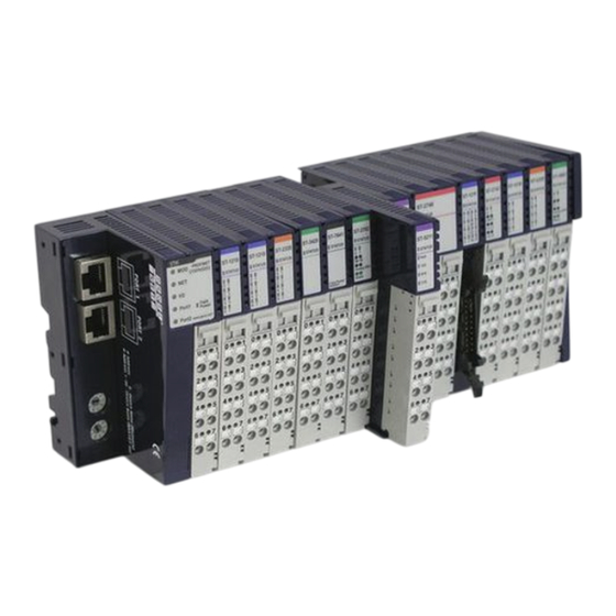
Nov 2019 Chapter 1: Introduction The PACSystems RSTi Network Interface and I/O family provides a cost effective, modular distributed I/O system. The RSTi network is ideally suited for distributed applications such as water/wastewater, process control, packaging and assembly. You can easily add RSTi modules to the system to build functional remote I/O stations to meet your application requirements. -
Page 15: I/O Station Capacity
User Manual Chapter 1 GFK-2745C Nov 2019 Sr. Number Label Reserved communication Port (Useful to only manufacturer) PUSH Lock for DIN rail Fieldbus Connector Module Number Marking (RTB Type) A set of interconnected RSTi modules can be chosen to suit the application and connected as a slave on a PROFIBUS or a PROFINET network. -
Page 16: Ioguidepro Tool
IOGuidePro Tool PACSystems RSTi Network adapters can be configured & monitored using IOGuidePro tool. You can use the IOGuidePro Tool to monitor & configure the following data: •... -
Page 17: Discrete Outputs
User Manual Chapter 1 GFK-2745C Nov 2019 • ST-121F Digital Input 16 Points, Positive Logic, 20P Connector, 12V/ 24Vdc • ST-1224 Digital Input 4 Points, Negative Logic, Terminal, 12/24Vdc • ST-1228 Digital Input 8 Points, Negative Logic, Terminal, 12V/24Vdc • ST-122F Digital Input 16 Points, Negative Logic, 20P Connector, 12V/ 24Vdc •... -
Page 18: Analog Outputs
User Manual Chapter 1 GFK-2745C Nov 2019 • ST-3214 AI 4 Channels, 4~20mA, 12-bit • ST-3218 AI 8 Channels, 4~20mA, 12bit • ST-3234 AI 4 Channels, 4~20mA, 14-bit • ST-3424 AI 4 Channels, 0~10Vdc, 12-bit • ST-3428 AI 8 Channels, 0~10V, 12bit •... -
Page 19: Accessories
User Manual Chapter 1 GFK-2745C Nov 2019 • ST-5221 Serial Interface RS-422, 1 Channel • ST-5231 Serial Interface RS-485, 1 Channel • ST-5232 Serial Interface RS-485, 2 Channels • ST-5351 SSI Interface 1 CH; 62.5K, 100K, 125K,250K,500K,1M,2Mbps • ST-5422 2 Channels, PWM Output, 1.5A/24VDC, Positive Logic •... -
Page 20: Chapter 2: Installation
User Manual Chapter 2 GFK-2745C Nov 2019 Chapter 2: Installation Module Mounting 2.1.1 How to mount on Din-Rail Press down the module lightly on the Din-Rail until it clicks. Figure 2 You can use the PUSH lock for DIN rail as a second locking mechanism. This lock will maintain module intact to DIN rail. -
Page 21: How To Dismount From Din-Rail
User Manual Chapter 2 GFK-2745C Nov 2019 2.1.2 How to dismount from Din-Rail Pull down the locking mechanism by using a small flat screw driver as shown in the following illustration. Figure 4 Push the lock on the side of module, pull up the module to remove from the din rail. Figure 5 Installation... -
Page 22: Installing And Removing Components
User Manual Chapter 2 GFK-2745C Nov 2019 2.1.3 Installing and Removing Components To plug in the module, use a small-bladed screwdriver and push down the locking lever located at bottom of the module. Install the module on DIN rail firmly; push up the locking lever to lock. -
Page 23: Rsti Io Station Spacing
User Manual Chapter 2 GFK-2745C Nov 2019 2.1.5 RSTi IO Station spacing Figure 8 All the dimensions mentioned are in ‘mm’. RSTi Network adapter and IO modules should be mounted horizontally with minimum clearance as shown above to meet product performance and reliability specifications by providing adequate airflow around the modules. -
Page 24: Rsti Bus Data Pin & Field Power Pin Description
User Manual Chapter 2 GFK-2745C Nov 2019 Connecting Shielded Cables Observe the following when installing shielding: Strip the outer cable sheath to the desired length. The appropriate length depends on the connection position of the wires and whether there should be a large or a small space between the connection point and the shield connection. -
Page 25: Rsti Data Bus System
User Manual Chapter 2 GFK-2745C Nov 2019 2.1.8 RSTi Data Bus System Figure 9 • Network Adapter Module: The Network Adapter Module forms the link between the field bus and the field devices through IO Modules. The connection to different field bus systems can be established by each of the corresponding Network Adapter Modules: PROFIBUS, CANopen, DeviceNet, Ethernet/IP, CC-Link, MODBUS/Serial, MODBUS/TCP, PROFINET etc. -
Page 26: Chapter 3: Power Modules
User Manual Chapter 3 GFK-2745C Nov 2019 Chapter 3: Power Modules The Power Supply Modules prevent the lack of power capacity within Network Adaptor module during expansion of module. There is also a Field Power Distributor to divide the AC and DC from Field Power during module expansion. -
Page 27: Specification
User Manual Chapter 3 GFK-2745C Nov 2019 3.1.2 Specification The following table describes the Input Specifications and the General Specifications for ST- 7008. Table 3: ST-7008: Input and General Specifications Items Specification Input Specification Field Power Voltage Shield signal Contacts Current Maximum10A Indicators Non Indicate... -
Page 28: Interface And Data
User Manual Chapter 3 GFK-2745C Nov 2019 ST-7108 3.2.1 Interface and Data The following illustration shows the interface design for ST-7108. Figure 12: Power Modules ST-7108 The following table lists the pin numbers and description for ST-7108. Table 4: ST-7108: Pin Description Pin Number Description Pin Number... -
Page 29: Specification
User Manual Chapter 3 GFK-2745C Nov 2019 3.2.2 Specification The following table describes the Input Specifications and the General Specifications for ST- 7108. Table 5: ST-7108 Input and General Specifications Items Specification Input Specification Field Power Voltage Contacts Current Maximum10A Indicators No Indication General Specification... -
Page 30: Interface And Data
User Manual Chapter 3 GFK-2745C Nov 2019 ST-7111 3.3.1 Interface and Data The following illustration shows the interface design for ST-7111. Figure 14: Power Modules ST-7111 The following table lists the pin numbers and description for ST-7111. Table 6: ST-7111 Pin Description Pin Number Description Pin Number... -
Page 31: Specification
User Manual Chapter 3 GFK-2745C Nov 2019 3.3.2 Specification The following table describes the Input Specifications and the General Specifications for ST- 7111. Table 7: ST-7111 Input and General Specifications Items Specification Input Specification System Input Voltage range 11Vdc to 28.8Vdc System Power Input Voltage Normal 24Vdc Field Power Input Voltage... -
Page 32: Interface And Data
User Manual Chapter 3 GFK-2745C Nov 2019 ST-7118 3.4.1 Interface and Data The following illustration shows the interface design for ST-7118. Figure 16: Power Modules ST-7118 The following table lists the pin numbers and description for ST-7118. Table 8: ST-7118: Pin Description Pin Number Description Pin Number... -
Page 33: Specification
User Manual Chapter 3 GFK-2745C Nov 2019 3.4.2 Specification The following table describes the Input Specifications and the General Specifications for ST- 7118. Table 9: ST-7118: Input and General Specifications Items Specification Input Specification Field Power Voltage 24Vdc Contacts Current Maximum10A Indicators No Indication... -
Page 34: Interface And Data
User Manual Chapter 3 GFK-2745C Nov 2019 ST-7188 3.5.1 Interface and Data The following illustration shows the interface design for ST-7188. Figure 18: Power Modules ST-7188 The following table lists the pin numbers and description for ST-7188. Table 10: ST-7188 Pin Description Pin Number Description Pin Number... -
Page 35: Specification
User Manual Chapter 3 GFK-2745C Nov 2019 3.5.2 Specification The following table describes the Input Specifications and the General Specifications for ST- 7188. Table 11: ST-7188 Input and General Specifications Items Specification Input Specification Field Power Voltage 24Vdc, 0Vdc Contacts Current Maximum10A Indicators No Indication... -
Page 36: Interface And Data
User Manual Chapter 3 GFK-2745C Nov 2019 ST-7241 3.6.1 Interface and Data The following illustration shows the interface design for ST-7241. Figure 19: Power Modules ST-7241 The following table lists the pin numbers and description for ST-7241. Table 12: ST-7241 Pin Description Pin Number Description Pin Number... -
Page 37: Specification
User Manual Chapter 3 GFK-2745C Nov 2019 3.6.2 Specification The following table describes the Input Specifications and the General Specifications for ST- 7241. Table 13: ST-7241 Input and General Specifications Items Specification Input Specification Field Power Voltage Arbitrary Field Power Contacts Current Maximum10A Indicators No Indication... -
Page 38: Example
User Manual Chapter 3 GFK-2745C Nov 2019 3.6.3 Example When you have a RSTi setup and need to use different Field Power Voltage, you can use the ST-7241 to change the distributed Voltage from 5Vdc/12Vdc/24Vdc /48Vdc, or from 110Vac/240Vac as below: Figure 20: Example ST-7241 Power Modules... -
Page 39: Interface And Data
User Manual Chapter 3 GFK-2745C Nov 2019 ST-7408 3.7.1 Interface and Data The following illustration shows the interface design for ST-7408. Figure 21: Power Modules ST-7408 The following table lists the pin numbers and description for ST-7408. Table 14: ST-7408 Pin Description Pin Number Description Pin Number... -
Page 40: Specification
User Manual Chapter 3 GFK-2745C Nov 2019 3.7.2 Specification The following table describes the Input Specifications and the General Specifications for ST- 7408. Table 15: ST-7408 Input and General Specifications Items Specification Input Specification Field Power Voltage Shield Indicators 1 Green/Red LED, Module Status Field Power Contacts Current Maximum10A RSTi Bus Power Contactor... -
Page 41: Interface And Data
User Manual Chapter 3 GFK-2745C Nov 2019 ST-7508 3.8.1 Interface and Data The following illustration shows the interface design for ST-7508. Figure 23: Power Modules ST-7508 The following table lists the pin numbers and description for ST-7508. Table 16: ST-7508 Pin Description Pin Number Description Pin Number... -
Page 42: Specification
User Manual Chapter 3 GFK-2745C Nov 2019 3.8.2 Specification The following table describes the Input Specifications and the General Specifications for ST- 7508. Table 17: ST-7508 Input and General Specifications Items Specification Input Specification Field Power Voltage 0Vdc Indicators 1 Green/Red LED, Module Status Field power Contacts Current Maximum 10A RSTi Bus Power Contactor... -
Page 43: Interface And Data
User Manual Chapter 3 GFK-2745C Nov 2019 ST-7511 3.9.1 Interface and Data The following illustration shows the interface design for ST-7511. Figure 25: Example ST-7508 The following table lists the pin numbers and description for ST-7511. Table 18: ST-7511 Pin Description Pin Number Description Pin Number... -
Page 44: Specification
User Manual Chapter 3 GFK-2745C Nov 2019 3.9.2 Specification The following table describes the Input Specifications and the General Specifications for ST- 7511. Table 19: ST-7511 Input and General Specifications Items Specification Input Specification System Input Voltage range 11Vdc to 28.8Vdc System Power Input Voltage Normal 24Vdc Indicators... -
Page 45: Interface And Data
User Manual Chapter 3 GFK-2745C Nov 2019 3.10 ST-7518 3.10.1 Interface and Data The following illustration shows the interface design for ST-7518. Figure 27: Power Modules ST-7518 The following table lists the pin numbers and description for ST-7518. Table 20: ST-7518 Pin Description Pin Number Description Pin Number... -
Page 46: Specification
User Manual Chapter 3 GFK-2745C Nov 2019 3.10.2 Specification The following table describes the Input Specifications and the General Specifications for ST- 7518. Table 21: ST-7518 Input and General Specifications Items Specification Input Specification Field Power Voltage 24Vdc Indicators 1 Green/Red LED, Module Status Field Power Contacts Current Maximum 10A General Specification... -
Page 47: Example
User Manual Chapter 3 GFK-2745C Nov 2019 3.11 ST-7588 3.11.1 Interface and Data The following illustration shows the interface design for ST-7588. Figure 29: Example ST-7518 The following table lists the pin numbers and description for ST-7588. Table 22: ST-7588 Pin Description Pin Number Description Pin Number... -
Page 48: Specification
User Manual Chapter 3 GFK-2745C Nov 2019 3.11.2 Specification The following table describes the Input Specifications and the General Specifications for ST- 7588. Table 23: ST-7588 Input and General Specifications Items Specification Input Specification Field Power Voltage 24Vdc, 0Vdc Indicators 1 Green/Red LED, Module Status Field Power Contacts Current Maximum 10A... -
Page 49: St-7641
User Manual Chapter 3 GFK-2745C Nov 2019 3.12 ST-7641 3.12.1 Interface and Data The following illustration shows the interface design for ST-7641. Figure 31: Power Modules ST-7641 The following table lists the pin numbers and description for ST-7641. Table 24: ST-7641 Pin Description Pin Number Description Pin Number... -
Page 50: Specification
User Manual Chapter 3 GFK-2745C Nov 2019 3.12.2 Specification The following table describes the Input Specifications and the General Specifications for ST- 7641. Table 25: ST-7641 Input and General Specifications Items Specification Input Specification Field Power Voltage Arbitrary Indicators 1 Green/Red LED, Module Status Field Power Contacts Current Maximum10A General Specification... -
Page 51: Dimension
User Manual Chapter 3 GFK-2745C Nov 2019 3.13 Dimension 3.13.1 ST-7xxx The following illustration shows the dimensions for ST-7xxx series. Figure 33: ST-7xxx Dimension 3.14 Diagnostics 3.14.1 Normal Module The LEDs indicate the status of the power modules. The table below shows the corresponding functions of LEDs during normal operation. -
Page 52: Chapter 4: Discrete Inputs
User Manual Chapter 4 GFK-2745C Nov 2019 Chapter 4: Discrete Inputs Discrete input modules range from DC 5V, DC 24V, DC 48V, AC 110V up to AC 240V. Each part is available with 4 to 16 points. ST-1114 4.1.1 Interface and Data The following illustration shows the interface design for ST-1114. - Page 53 User Manual Chapter 4 GFK-2745C Nov 2019 4.1.2 Specification The following table describes the Input Specifications and the General Specifications for ST- 1114. Table 28: ST-1114: Input and General Specifications Items Specification Input Specification Inputs Per Module 4 Points, Positive Logic Indicators 4 Green Input States, 1 Green/Red RSTi Bus State ON-state Voltage...
- Page 54 User Manual Chapter 4 GFK-2745C Nov 2019 ST-1124 4.2.1 Interface and Data The following illustration shows the interface design for ST-1124. Figure 35: Discrete Input Module: ST-1124 The following table lists the pin numbers and description for ST-1124. Table 29: ST-1124: Pin Description Pin Number Description Pin Number...
- Page 55 User Manual Chapter 4 GFK-2745C Nov 2019 4.2.2 Specification The following table describes the Input Specifications and the General Specifications for ST- 1124. Table 30: ST-1124 Input and General Specifications Items Specification Input Specification Inputs Per Module 4 Points, Negative Logic Indicators 4 Green Input States, 1 Green/Red RSTi Bus State ON-state Voltage...
-
Page 56: Interface And Data
User Manual Chapter 4 GFK-2745C Nov 2019 ST-1214 4.3.1 Interface and Data The following illustration shows the interface design for ST-1214. Figure 36: Discrete Input Module ST-1214 The following table lists the pin numbers and description for ST-1214 Table 31: ST-1214 Pin Description Pin Number Description Pin Number... -
Page 57: Specification
User Manual Chapter 4 GFK-2745C Nov 2019 4.3.2 Specification The following table describes the Input Specifications and the General Specifications for ST- 1214. Table 32: ST-1214 Input and General Specifications Items Specification Input Specification Inputs Per Module 4 Points, Positive Logic Indicators 4 Green Input States, 1 Green/Red RSTi Bus State ON-state Voltage... -
Page 58: Interface And Data
User Manual Chapter 4 GFK-2745C Nov 2019 ST-1218 4.4.1 Interface and Data The following illustration shows the interface design for ST-1218. Figure 37: Discrete Input Module ST-1218 The following table lists the pin numbers and description for ST-1218. Table 33: ST-1218 Pin Description Pin Number Description Pin Number... -
Page 59: Specification
User Manual Chapter 4 GFK-2745C Nov 2019 4.4.2 Specification The following table describes the Input Specifications and the General Specifications for ST- 1218. Table 34: ST-1218 Input and General Specifications Items Specification Input Specification Inputs Per Module 8 Points, Positive Logic Indicators 8 Green Input States, 1 Green/Red RSTi Bus State ON-state Voltage... -
Page 60: Interface And Data
User Manual Chapter 4 GFK-2745C Nov 2019 ST-121F 4.5.1 Interface and Data The following illustration shows the interface design for ST-121F. Figure 38: Discrete Input Module ST-121F The following table lists the pin numbers and description for ST-121F. Table 35: ST-121F Pin Description Pin Number Description Pin Number... -
Page 61: Specification
User Manual Chapter 4 GFK-2745C Nov 2019 4.5.2 Specification The following table describes the Input Specifications and the General Specifications for ST- 121F. Table 36: ST-121F Input and General Specifications Items Specification Input Specification Inputs Per Module 16 Points, Positive Logic Indicators 16 Green Input States, 1 Green/Red RSTi Bus State ON-state Voltage... - Page 62 User Manual Chapter 4 GFK-2745C Nov 2019 ST-1224 4.6.1 Interface and Data The following illustration shows the interface design for ST-1224. Figure 39: Discrete Input Module ST-1224 The following table lists the pin numbers and description for ST-1224. Table 37: ST-1224 Pin Description Pin Number Description Pin Number...
-
Page 63: Specification
User Manual Chapter 4 GFK-2745C Nov 2019 4.6.2 Specification The following table describes the Input Specifications and the General Specifications for ST- 1224. Table 38: ST-1224: Input and General Specifications Items Specification Input Specification Inputs Per Module 4 Points, Negative Logic Indicators 4 Green Input States, 1 Green/Red RSTi Bus State ON-state Voltage... -
Page 64: Interface And Data
User Manual Chapter 4 GFK-2745C Nov 2019 ST-1228 4.7.1 Interface and Data The following illustration shows the interface design for ST-1228. Figure 40: Discrete Input Module ST-1228 The following table lists the pin numbers and description for ST-1228. Table 39: ST-1228 Pin Description Pin Number Description Pin Number... -
Page 65: Specification
User Manual Chapter 4 GFK-2745C Nov 2019 4.7.2 Specification The following table describes the Input Specifications and the General Specifications for ST- 1228. Table 40: ST-1228: Input and General Specifications Items Specification Input Specification Inputs Per Module 8 Points, Negative Logic Indicators 8 Green Input States, 1 Green/Red RSTi Bus State ON-state Voltage... -
Page 66: Interface And Data
User Manual Chapter 4 GFK-2745C Nov 2019 ST-122F 4.8.1 Interface and Data The following illustration shows the interface design for ST-122F. Figure 41: Discrete Input Module ST-122F The following table lists the pin numbers and description for ST-122F. Table 41: ST-122F Pin Description Pin Number Description Pin Number... -
Page 67: Specification
User Manual Chapter 4 GFK-2745C Nov 2019 4.8.2 Specification The following table describes the Input Specifications and the General Specifications for ST- 122F. Table 42: ST-122F Input and General Specifications Items Specification Input Specification Inputs Per Module 16 Points, Negative Logic Indicators 16 Green Input States, 1 Green/Red RSTi Bus State ON-state Voltage... - Page 68 User Manual Chapter 4 GFK-2745C Nov 2019 ST-1314 The following illustration shows the interface design for ST-1314. Figure 42: Discrete Input Module ST-1314 The following table lists the pin numbers and description for ST-1314. Table 43: ST-1314 Pin Description Pin Number Description Pin Number Description...
-
Page 69: Specification
User Manual Chapter 4 GFK-2745C Nov 2019 4.9.1 Specification The following table describes the Input Specifications and the General Specifications for ST- 1314. Table 44: ST-1314 Input and General Specifications Items Specification Input Specification Inputs Per Module 4 Points, Positive Logic Indicators 4 Green Input States, 1 Green/Red RSTi Bus State ON-state Voltage... -
Page 70: Interface And Data
User Manual Chapter 4 GFK-2745C Nov 2019 4.10 ST-131F 4.10.1 Interface and Data The following illustration shows the interface design for ST-131F. Figure 43: Discrete Input Module ST-131F The following table lists the pin numbers and description for ST-131F. Table 45: ST-131F Pin Description Pin Number Description Pin Number... -
Page 71: Specification
User Manual Chapter 4 GFK-2745C Nov 2019 4.10.2 Specification The following table describes the Input Specifications and the General Specifications for ST- 131F. Table 46: ST-131F Input and General Specifications Items Specification Input Specification Inputs Per Module 16 Points, Positive Logic Indicators 16 Green Input States, 1 Green/Red RSTi Bus State ON-state Voltage... - Page 72 User Manual Chapter 4 GFK-2745C Nov 2019 4.11 ST-1324 4.11.1 Interface and Data The following illustration shows the interface design for ST-1324. Figure 44: Discrete Input Module ST-1324 The following table lists the pin numbers and description for ST-1324. Table 47: ST-1324 Pin Description Pin Number Description Pin Number...
-
Page 73: Specification
User Manual Chapter 4 GFK-2745C Nov 2019 4.11.2 Specification The following table describes the Input Specifications and the General Specifications for ST- 1324. Table 48: ST-1324 Input and General Specifications Items Specification Input Specification Inputs Per Module 4 Points, Negative Logic Indicators 4 Green Input States, 1 Green/Red RSTi Bus State ON-state Voltage... -
Page 74: Interface And Data
User Manual Chapter 4 GFK-2745C Nov 2019 4.12 ST-1804 4.12.1 Interface and Data The following illustration shows the interface design for ST-1804. Figure 45: Discrete Input Module ST-1324 The following table lists the pin numbers and description for ST-1804. Table 49: ST-1804 Pin Description Pin Number Description Pin Number... -
Page 75: Specification
User Manual Chapter 4 GFK-2745C Nov 2019 4.12.2 Specification The following table describes the Input Specifications and the General Specifications for ST- 1804. Table 50: ST-1804 Input and General Specifications Items Specification Input Specification Inputs Per Module 4 Points Indicators 4 Green Input States, 1 Green/Red RSTi Bus State ON-state Voltage 110Vac nominal... -
Page 76: Interface And Data
User Manual Chapter 4 GFK-2745C Nov 2019 4.13 ST-1904 4.13.1 Interface and Data The following illustration shows the interface design for ST-1904. Figure 46: Discrete Input Module ST-1904 The following table lists the pin numbers and description for ST-1904. Table 51: ST-1904 Pin Description Pin Number Description Pin Number... -
Page 77: Specification
User Manual Chapter 4 GFK-2745C Nov 2019 4.13.2 Specification The following table describes the Input Specifications and the General Specifications for ST- 1904. Table 52: ST-1904 Input and General Specifications Items Specification Input Specification Inputs Per Module 4 Points Indicators 4 Green Input States, 1 Green/Red RSTi Bus State ON-state Voltage 240Vac nominal... -
Page 78: Dimension
User Manual Chapter 4 GFK-2745C Nov 2019 4.14 Dimension 4.14.1 ST-1xx4 and ST-1xx8 The following illustration shows the dimensions for ST-1xx4 and ST-1xx8 series. Figure 47: ST-1xxs and ST-1xx8 Dimensions 4.14.2 ST-1xxF The following illustration shows the dimension for ST-1xxF. Figure 48: ST-1xxF Dimension Discrete Inputs... -
Page 79: Mapping Data Into The Image Table
User Manual Chapter 4 GFK-2745C Nov 2019 4.15 Mapping Data into the Image Table 4.15.1 ST-1xx4 Input Module Data Input Image Value Bit No Bit 7 Bit 6 Bit 5 Bit 4 Bit 3 Bit 2 Bit 1 Bit 0 Byte 0 Reserved 4.15.2... -
Page 80: Diagnostics
User Manual Chapter 4 GFK-2745C Nov 2019 4.16 Diagnostics 4.16.1 Normal Module The LEDs indicate the status of the module. The table below shows the corresponding functions of LEDs during normal operation. You can use this table as a reference for troubleshooting errors. -
Page 81: Chapter 5: Discrete Output
User Manual Chapter 5 GFK-2745C Nov 2019 Chapter 5: Discrete Output Discrete Output Modules consists of Negative Logic Type, Positive Logic Type, Relay, and Triac modules ranging from 2 points to 16 points. DC 24V/0.5 type is available with 4 points and 8 points and DC 24V/0.3A type is available with 16 points. -
Page 82: Specification
User Manual Chapter 5 GFK-2745C Nov 2019 5.1.2 Specification The following table describes the Output Specifications and the General Specifications for ST-2114. Table 55: ST-2114 Output and General Specifications Items Specification Output Specification Outputs Per Module 4 Points, TTL Inverting (Positive Logic) Output (Default:5V) Indicators 4 Green Output States, 1 Green/Red RSTi Bus State Output Voltage Range... -
Page 83: Interface And Data
User Manual Chapter 5 GFK-2745C Nov 2019 ST-2124 5.2.1 Interface and Data The following illustration shows the interface design for ST-2124. Figure 50: Discrete Output Module ST-2124 The following table lists the pin numbers and description for ST-2124. Table 56: ST-2124 Pin Description Pin Number Description Pin Number... -
Page 84: Specification
User Manual Chapter 5 GFK-2745C Nov 2019 5.2.2 Specification The following table describes the Output Specifications and the General Specifications for ST-2124. Table 57: ST-2124 Output and General Specifications Items Specification Output Specification Outputs Per Module 4 Points, TTL Non-Inverting (Positive Logic) Output (Default: Indicators 4 Green Output States, 1 Green/Red RSTi Bus State Output Voltage Range... -
Page 85: Interface And Data
User Manual Chapter 5 GFK-2745C Nov 2019 ST-2314 5.3.1 Interface and Data The following illustration shows the interface design for ST-2314. Figure 51: Discrete Output Module ST-2314 The following table lists the pin numbers and description for ST-2314. Table 58: ST-2314 Pin Description Pin Number Description Pin Number... -
Page 86: Specification
User Manual Chapter 5 GFK-2745C Nov 2019 5.3.2 Specification The following table describes the Output Specifications and the General Specifications for ST-2314. Table 59: ST-2314 Output and General Specifications Items Specification Output Specification Outputs Per Module 4 Points, Negative Logic Indicators 4 Green Output States, 1 Green/Red RSTi Bus State Output Voltage Range... -
Page 87: Interface And Data
User Manual Chapter 5 GFK-2745C Nov 2019 ST-2324 5.4.1 Interface and Data The following illustration shows the interface design for ST-2324. Figure 52: Discrete Output Module ST-2324 The following table lists the pin numbers and description for ST-2324. Table 60: ST-2324 Pin Description Pin Number Description Pin Number... -
Page 88: Specification
User Manual Chapter 5 GFK-2745C Nov 2019 5.4.2 Specification The following table describes the Output Specifications and the General Specifications for ST-2324. Table 61: ST-2324 Output and General Specifications Items Specification Output Specification Outputs Per Module 4 Points, Positive Logic Indicators 4 Green Output States Output Voltage Range... -
Page 89: Interface And Data
User Manual Chapter 5 GFK-2745C Nov 2019 ST-2414 5.5.1 Interface and Data The following illustration shows the interface design for ST-2414. Figure 53: Discrete Output Module ST-2324 The following table lists the pin numbers and description for ST-2414. Table 62: ST-2414 Pin Description Pin Number Description Pin Number... -
Page 90: Specification
User Manual Chapter 5 GFK-2745C Nov 2019 5.5.2 Specification The following table describes the Output Specifications and the General Specifications for ST-2414. Table 63: ST-2414 Output and General Specifications Items Specification Output Specification Outputs Per Module 4 Points, Negative Logic Indicators 4 Green/Red Output States, 1 Green/Red RSTi Bus State Output Voltage Range... - Page 91 User Manual Chapter 5 GFK-2745C Nov 2019 ST-2424 5.6.1 Interface and Data The following illustration shows the interface design for ST-2424. Figure 54: Discrete Output Module ST-2424 The following table lists the pin numbers and description for ST-2424. Table 64: ST-2424 Pin Description Pin Number Description Pin Number...
- Page 92 User Manual Chapter 5 GFK-2745C Nov 2019 5.6.2 Specification The following table describes the Output Specifications and the General Specifications for ST-2424. Table 65: ST-2424 Output and General Specifications Items Specification Output Specification Outputs Per Module 4 Points, Positive Logic Indicators 4 Green/Red Output States, 1 Green/Red RSTi Bus State Output Voltage Range...
-
Page 93: Interface And Data
User Manual Chapter 5 GFK-2745C Nov 2019 ST-2514 5.7.1 Interface and Data The following illustration shows the interface design for ST-2514. Figure 55: Discrete Output Module ST-2514 The following table lists the pin numbers and description for ST-2514. Table 66: ST-2514 Pin Description Pin Number Description Pin Number... -
Page 94: Specification
User Manual Chapter 5 GFK-2745C Nov 2019 5.7.2 Specification The following table describes the Output Specifications and the General Specifications for ST-2514. Table 67: ST-2514 Output and General Specifications Items Specification Output Specification Outputs Per Module 4 Points, Negative Logic Indicators 4 Green/Red Output States, 1 Green/Red RSTi Bus State Output Voltage Range... -
Page 95: Interface And Data
User Manual Chapter 5 GFK-2745C Nov 2019 ST-2524 5.8.1 Interface and Data The following illustration shows the interface design for ST-2524. Figure 56: Discrete Output Module ST-2524 The following table lists the pin numbers and description for ST-2524. Table 68: ST-2524 Pin Description Pin Number Description Pin Number... -
Page 96: Specification
User Manual Chapter 5 GFK-2745C Nov 2019 5.8.2 Specification The following table describes the Output Specifications and the General Specifications for ST-2524. Table 69: ST-2524 Output and General Specifications Items Specification Output Specification Outputs Per Module 4 Points, Positive Logic Indicators 4 Green/Red Output States, 1 Green/Red RSTi Bus State Output Voltage Range... -
Page 97: Interface And Data
User Manual Chapter 5 GFK-2745C Nov 2019 ST-2318 5.9.1 Interface and Data The following illustration shows the interface design for ST-2318. Figure 57: Discrete Output Module ST-2318 The following table lists the pin numbers and description for ST-2318. Table 70: ST-2318 Pin Description Pin Number Description Pin Number... -
Page 98: Specification
User Manual Chapter 5 GFK-2745C Nov 2019 5.9.2 Specification The following table describes the Output Specifications and the General Specifications for ST-2318. Table 71: ST-2318 Output and General Specifications Items Specification Output Specification Outputs Per Module 8 Points Negative Logic Indicators 8 Green Output States, 1 Green/Red RSTi Bus State Output Voltage Range... -
Page 99: Interface And Data
User Manual Chapter 5 GFK-2745C Nov 2019 5.10 ST-2328 5.10.1 Interface and Data The following illustration shows the interface design for ST-2328. Figure 58: Discrete Output Module ST-2328 The following table lists the pin numbers and description for ST-2328. Table 72: ST-2328 Pin Description Pin Number Description Pin Number... -
Page 100: Specification
User Manual Chapter 5 GFK-2745C Nov 2019 5.10.2 Specification The following table describes the Output Specifications and the General Specifications for ST-2328. Table 73: ST-2328 Output and General Specifications Items Specification Output Specification Outputs Per Module 8 Points, Positive Logic Indicators 8 Green Output States, 1 Green/Red RSTi Bus State Output Voltage Range... -
Page 101: St-221F
User Manual Chapter 5 GFK-2745C Nov 2019 5.11 ST-221F 5.11.1 Interface and Data The following snapshot details the interface design for ST-221F. Figure 59: Discrete Output Module ST-221F The following table lists the pin numbers and description for ST-221F. Table 74: ST-221F Pin Description Pin Number Description Pin Number... - Page 102 User Manual Chapter 5 GFK-2745C Nov 2019 5.11.2 Specification The following table describes the Output Specifications and the General Specifications for ST-221F. Table 75: ST-221F Output and General Specifications Items Specification Output Specification Outputs Per Module 16 Points, Negative Logic Indicators 4 Green Output States, 1 Green/Red RSTi Bus State Output Voltage Range...
-
Page 103: Interface And Data
User Manual Chapter 5 GFK-2745C Nov 2019 5.12 ST-222F 5.12.1 Interface and Data The following illustration shows the interface design for ST-222F. Figure 60: Discrete Output Module ST-222F The following table lists the pin numbers and description for ST-222F. Table 76: ST-222F Pin Description Pin Number Description Pin Number... - Page 104 User Manual Chapter 5 GFK-2745C Nov 2019 5.12.2 Specification The following table describes the Output Specifications and the General Specifications for ST-222F. Table 77: ST-222F Output and General Specifications Items Specification Output Specification Outputs Per Module 16 Points, Positive Logic Indicators 16 Green Output States, 1 Green/Red RSTi Bus State Output Voltage Range...
-
Page 105: Interface And Data
User Manual Chapter 5 GFK-2745C Nov 2019 5.13 ST-2742 5.13.1 Interface and Data The following illustration shows the interface design for ST-2742. Figure 61: Discrete Output Module ST-2742 The following table lists the pin numbers and description for ST-2742. Table 78: ST-2742 Pin Description Pin Number Description Pin Number... -
Page 106: Specification
User Manual Chapter 5 GFK-2745C Nov 2019 5.13.2 Specification The following table describes the Output Specifications and the General Specifications for ST-2742. Table 79: ST-2742 Output and General Specifications Items Specification Output Specification Outputs Per Module 2 Points Indicators 2 Green Output States, 1 Green/Red RSTi Bus State Relay type Form A, normally Open (N.O.) Single Pole, Single Throw(SPST) -
Page 107: St-2744
User Manual Chapter 5 GFK-2745C Nov 2019 5.14 ST-2744 5.14.1 Interface and Data The following illustration shows the interface design for ST-2744. Figure 62: Discrete Output Module ST-2744 The following table lists the pin numbers and description for ST-2744. Table 80: ST-2744 Pin Description Pin Number Description Pin Number... -
Page 108: Specification
User Manual Chapter 5 GFK-2745C Nov 2019 5.14.2 Specification The following table describes the Output Specifications and the General Specifications for ST-2744. Table 81: ST-2744 Output and General Specifications Items Specification Output Specification Outputs Per Module 4 Points Indicators 4 Green Output States, 1 Green/Red RSTi Bus State Relay type Form A, normally Open (N.O.) Single Pole, Single Throw(SPST) -
Page 109: St-2748
User Manual Chapter 5 GFK-2745C Nov 2019 5.15 ST-2748 5.15.1 Interface and Data The following illustration shows the interface design for ST-2748. Figure 63: Discrete Output Module ST-2748 Signal for Left Terminal The following table lists the pin numbers and description for ST-2748 Left Terminal. Table 82: ST-2748 Pin Description for Left Terminal Pin Number Description... -
Page 110: Specification
User Manual Chapter 5 GFK-2745C Nov 2019 5.15.2 Specification The following table describes the Output Specifications and the General Specifications for ST-2748. Table 84: ST-2748 Output and General Specifications Items Specification Output Specification Outputs Per Module 8 Points Indicators 8 Green Output States, 1 Green/Red RSTi Bus State Relay type Form A, normally Open(N.O.) Single Pole, Single Throw(SPST) -
Page 111: St-2852
User Manual Chapter 5 GFK-2745C Nov 2019 5.16 ST-2852 5.16.1 Interface and Data The following illustration shows the interface design for ST-2852. Figure 64: Discrete Output Module ST-2852 The following table lists the pin numbers and description for ST-2852. Table 85: ST-2852 Pin Description Pin Number Description Pin Number... -
Page 112: Specification
User Manual Chapter 5 GFK-2745C Nov 2019 5.16.2 Specification The following table describes the Output Specifications and the General Specifications for ST-2852. Table 86: ST-2852 Output and General Specifications Items Specification Output Specification Outputs Per Module 2 Points Indicators 2 Green Output Status, 1 Green/Red RSTi Bus State Switch Type Zero Crossing Rated Load Voltage... -
Page 113: Dimension
User Manual Chapter 5 GFK-2745C Nov 2019 5.17 Dimension 5.17.1 ST-2xx2, ST-2xx4, ST-2xx8 The following illustration shows the dimensions for ST-2xx2, ST-2xx4, and ST-2xx8 series. Figure 65: ST-2xx2, ST-2xx4, ST-2xx8 Dimensions 5.17.2 ST-2xxF The following illustration shows the dimensions for ST-2xxF series. Figure 66: ST-2xxF Dimension Discrete Output... -
Page 114: Mapping Data Into The Image Table
User Manual Chapter 5 GFK-2745C Nov 2019 5.18 Mapping Data into the Image Table 5.18.1 ST-2742, ST-2852 Output Image Value Bit No Bit 7 Bit 6 Bit 5 Bit 4 Bit 3 Bit 2 Bit 1 Bit 0 Byte 0 Reserved Output Module Data 5.18.2... -
Page 115: St-2Xxf
User Manual Chapter 5 GFK-2745C Nov 2019 5.18.4 ST-2xxF Output Image value Bit No Bit 7 Bit 6 Bit 5 Bit 4 Bit 3 Bit 2 Bit 1 Bit 0 Byte 0 Byte 1 Output Module Data Discrete Output... -
Page 116: Chapter 6: Analog Input
User Manual Chapter 6 GFK-2745C Nov 2019 Chapter 6: Analog Input Analog Input Modules are available with 12 bit and 14-bit input modules according to their input value based of 4/8 Channels. RTD and TC modules of 2 channels are also available. ST-3114 6.1.1 The Interface and Data... -
Page 117: Specification
User Manual Chapter 6 GFK-2745C Nov 2019 6.1.2 Specification The following table describes the Input Specifications and the General Specifications for ST- 3114. Table 88: ST-3114 Input and General Specifications Items Specification Input Specification Number of Inputs 4 Channels Single Ended, Non-isolated Between Channels Indicators 4 Green/Red States, 1 Green/Red RSTi Bus State Resolution in Ranges... -
Page 118: Interface And Data
User Manual Chapter 6 GFK-2745C Nov 2019 ST-3118 6.2.1 Interface and Data The following illustration shows the interface design for ST-3118. Figure 68: Analog Input Module ST-3118 The following table lists the pin numbers and their description for ST-3118. Table 89: ST-3118 Pin Description Pin Number Description Pin Number... -
Page 119: Specification
User Manual Chapter 6 GFK-2745C Nov 2019 6.2.2 Specification The following table describes the Input Specifications and the General Specifications for ST- 3118. Table 90: ST-3118 Input and General Specifications Items Specification Input Specification Number of Inputs 8 Channels Single Ended Indicators 1 Green/Red RSTi Bus State Resolution in Ranges... -
Page 120: Interface And Data
User Manual Chapter 6 GFK-2745C Nov 2019 ST-3134 6.3.1 Interface and Data The following illustration shows the interface design for ST-3134. Figure 69: Analog Input Module ST-3134 The following table lists the pin numbers and their description for ST-3134. Table 91: ST-3134 Pin Description Pin Number Description Pin Number... -
Page 121: Specification
User Manual Chapter 6 GFK-2745C Nov 2019 6.3.2 Specification The following table describes the Input Specifications and the General Specifications for ST- 3134. Table 92: ST-3134 Input and General Specifications Items Specification Input Specification Number of Inputs 4 Channels Single Ended, Non-isolated Between Channels Indicators 4 Green/Red States, 1 Green/Red RSTi Bus State Resolution in Ranges... -
Page 122: Interface And Data
User Manual Chapter 6 GFK-2745C Nov 2019 ST-3214 6.4.1 Interface and Data The following illustration shows the interface design for ST-3214. Figure 70: Analog Input Module ST-3214 The following table lists the pin numbers and their description for ST-3214. Table 93: ST-3214 Pin Description Pin Number Description Description... -
Page 123: Specification
User Manual Chapter 6 GFK-2745C Nov 2019 6.4.2 Specification The following table describes the Input Specifications and the General Specifications for ST- 3214. Table 94: ST-3214 Input and General Specifications Items Specification Input Specification Number of Inputs 4 Channels Single Ended, Non-isolated Between Channels Indicators 4 Green/Red States, 1 Green/Red RSTi Bus State Resolution in Ranges... -
Page 124: Interface And Data
User Manual Chapter 6 GFK-2745C Nov 2019 ST-3218 6.5.1 Interface and Data The following illustration shows the interface design for ST-3218. Figure 71: Analog Input Module ST-3218 The following table lists the pin numbers and their description for ST-3218. Table 95: ST-3218 Pin Description Pin Number Description Pin Number... -
Page 125: Specification
User Manual Chapter 6 GFK-2745C Nov 2019 6.5.2 Specification The following table describes the Input Specifications and the General Specifications for ST- 3218. Table 96: ST-3218 Input and General Specifications Items Specification Input Specification Number of Inputs 8 Channels Single Ended Indicators 1 Green/Red RSTi Bus State Resolution in Ranges... -
Page 126: Interface And Data
User Manual Chapter 6 GFK-2745C Nov 2019 ST-3234 6.6.1 Interface and Data The following illustration shows the interface design for ST-3234. Figure 72: Analog Input Module ST-3234 The following table lists the pin numbers and their description for ST-3234. Table 97: ST-3234 Pin Description Pin Number Description Pin Number... -
Page 127: Specification
User Manual Chapter 6 GFK-2745C Nov 2019 6.6.2 Specification The following table describes the Input Specifications and the General Specifications for ST- 3234. Table 98: ST-3234 Input and General Specifications Items Specification Input Specification Number of Inputs 4 Channels Single Ended, Non-isolated Between Channels Indicators 4 Green/Red States, 1 Green/Red RSTi Bus State Resolution in Ranges... -
Page 128: Interface And Data
User Manual Chapter 6 GFK-2745C Nov 2019 ST-3424 6.7.1 Interface and Data The following illustration shows the interface design for ST-3424. Figure 73: Analog Input Module ST-3424 The following table lists the pin numbers and their description for ST-3424. Table 99: ST-3424 Pin Description Pin Number Description Pin Number... -
Page 129: Specification
User Manual Chapter 6 GFK-2745C Nov 2019 6.7.2 Specification The following table describes the Input Specifications and the General Specifications for ST- 3424. Table 100: ST-3424 Input and General Specifications Items Specification Input Specification Number of Inputs 4 Channels Single Ended, Non-isolated Between Channels Indicators 4 Green States, 1 Green/Red RSTi Bus State Resolution in Ranges... -
Page 130: Interface And Data
User Manual Chapter 6 GFK-2745C Nov 2019 ST-3428 6.8.1 Interface and Data The following illustration shows the interface design for ST-3428. Figure 74: Analog Input Module ST-3428 The following table lists the pin numbers and their description for ST-3428. Table 101: ST-3428 Pin Description Pin Number Description Pin Number... -
Page 131: Specification
User Manual Chapter 6 GFK-2745C Nov 2019 6.8.2 Specification The following table describes the Input Specifications and the General Specifications for ST- 3428. Table 102: ST-3428 Input and General Specifications Items Specification Input Specification Number of Inputs 8 Channels Single Ended Indicators 1 Green/Red RSTi Bus State Resolution in Ranges... -
Page 132: Interface And Data
User Manual Chapter 6 GFK-2745C Nov 2019 ST-3444 6.9.1 Interface and Data The following illustration shows the interface design for ST-3444. Figure 75: Analog Input Module ST-3444 The following table lists the pin numbers and their description for ST-3444. Table 103: ST-3444 Pin Description Pin Number Description Pin Number... -
Page 133: Specification
User Manual Chapter 6 GFK-2745C Nov 2019 6.9.2 Specification The following table describes the Input Specifications and the General Specifications for ST- 3444. Table 104: ST-3444 Input and General Specifications Items Specification Input Specification Number of Inputs 4 Channels Single Ended, Non-isolated Between Channels Indicators 4 Green/Red States, 1 Green/Red RSTi Bus State Resolution in Ranges... -
Page 134: St-3524
User Manual Chapter 6 GFK-2745C Nov 2019 6.10 ST-3524 6.10.1 Interface and Data The following illustration shows the interface design for ST-3524. Figure 76: Analog Input Module ST-3524 The following table lists the pin numbers and their description for ST-3524. Table 105: ST-3524 Pin Description Pin Number Description... -
Page 135: Specification
User Manual Chapter 6 GFK-2745C Nov 2019 6.10.2 Specification The following table describes the Input Specifications and the General Specifications for ST- 3524. Table 106: ST-3524 Input and General Specifications Items Specification Input Specification Number of Inputs 4 Channels Single Ended, Non-isolated Between Channels Indicators 4 Green/Red States, 1 Green/Red RSTi Bus State Resolution in Ranges... - Page 136 User Manual Chapter 6 GFK-2745C Nov 2019 6.11 ST-3544 6.11.1 Interface and Data The following illustration shows the interface design for ST-3544. Figure 77: Analog Input Module ST-3544 The following table lists the pin numbers and their description for ST-3544. Table 107: ST-3544 Pin Description Pin Number Description...
- Page 137 User Manual Chapter 6 GFK-2745C Nov 2019 6.11.2 Specification The following table describes the Input Specifications and the General Specifications for ST- 3544. Table 108: ST-3544 Input and General Specifications Items Specification Input Specification Number of Inputs 4 Channels Single Ended, Non-isolated Between Channels Indicators 4 Green/Red States, 1 Green/Red RSTi Bus State Resolution in Ranges...
- Page 138 User Manual Chapter 6 GFK-2745C Nov 2019 6.12 ST-3624 6.12.1 Interface and Data The following illustration shows the interface design for ST-3624. Figure 78: Analog Input Module ST-3624 The following table lists the pin numbers and their description for ST-3624. Table 109: ST-3624 Pin Description Pin Number Description...
- Page 139 User Manual Chapter 6 GFK-2745C Nov 2019 6.12.2 Specification The following table describes the Input Specifications and the General Specifications for ST- 3624. Table 110: ST-3624 Input and General Specifications Items Specification Input Specification Number of Inputs 4 Channels Single Ended, Non-isolated Between Channels Indicators 4 Green/Red States, 1 Green/Red RSTi Bus State Resolution in Ranges...
- Page 140 User Manual Chapter 6 GFK-2745C Nov 2019 6.13 ST-3644 6.13.1 Interface and Data The following illustration shows the interface design for ST-3644. Figure 79: Analog Input Module ST-3644 The following table lists the pin numbers and their description for ST-3644. Table 111: ST-3644 Pin Description Pin Number Description...
- Page 141 User Manual Chapter 6 GFK-2745C Nov 2019 6.13.2 Specification The following table describes the Input Specifications and the General Specifications for ST- 3644. Table 112: ST-3644 Input and General Specifications Items Specification Input Specification Number of Inputs 4 Channels Single Ended, Non-isolated Between Channels Indicators 4 Green/Red States, 1 Green/Red RSTi Bus State Resolution in Ranges...
- Page 142 User Manual Chapter 6 GFK-2745C Nov 2019 6.14 ST-3702 6.14.1 Interface and Data The following illustration shows the interface design for ST-3702. Figure 80: Analog Input Module ST-3702 The following table lists the pin numbers and their description for ST-3702. Table 113: ST-3702 Pin Description Pin Number Description...
- Page 143 User Manual Chapter 6 GFK-2745C Nov 2019 Sensor Type Data The following table lists the data related to Sensor Type. Table 114: ST-3702 Pin Description Sensor Type Degree Counts Resolution Resistance 100mΩ 1~2000Ω 10~20000 100mΩ / 1count Resistance 10mΩ 1~327Ω 10~3270 10mΩ...
- Page 144 User Manual Chapter 6 GFK-2745C Nov 2019 Items Specification Module Error ±0.1% Full Scale @25℃ ±0.3% Full Scale @0℃, 60℃ Calibration Not Required Diagnostic Channel Open (if it is not Connected, Data=0x8000) Common Type 2 Channels/2 COM (Single Channel) General Specification Power Supply From System Power DC/DC Power Dissipation...
- Page 145 User Manual Chapter 6 GFK-2745C Nov 2019 6.15 ST-3704 6.15.1 Interface and Data The following illustration shows the interface design for ST-3704. Figure 81: Analog Input Module ST-3704 The following table lists the pin numbers and their description for ST-3704. Table 116: ST-3704 Pin Description Pin Number Description...
- Page 146 User Manual Chapter 6 GFK-2745C Nov 2019 6.15.2 Specification The following table describes the Input Specifications and the General Specifications for ST- 3704. Table 117: ST-3704 Input and General Specifications Items Specification Input Specification Number of Inputs 4 Channels Indicators 1 Green/Red Status, 4 Green States Sensor Types RTD Input...
- Page 147 User Manual Chapter 6 GFK-2745C Nov 2019 6.16 ST-3708 6.16.1 Interface and Data The following illustration shows the interface design for ST-3708. Figure 82: Analog Input Module ST-3708 The following table lists the pin numbers and their description for ST-3708. Table 118: ST-3708 Pin Description Pin Number Description...
- Page 148 User Manual Chapter 6 GFK-2745C Nov 2019 6.16.2 Specification The following table describes the Input Specifications and the General Specifications for ST- 3708. Table 119: ST-3708 Input and General Specifications Items Specification Input Specification Number of Inputs 8 Channels Indicators 1 Green/Red LED, Module Status, 8 Green LED, Input State Sensor Types RTD Input...
- Page 149 User Manual Chapter 6 GFK-2745C Nov 2019 6.17 ST-3802 6.17.1 Interface and Data The following illustration shows the interface design for ST-3802. Figure 83: Analog Input Module ST-3802 The following table lists the pin numbers and their description for ST-3802. Table 120: ST-3802 Pin Description Pin Number Description...
- Page 150 User Manual Chapter 6 GFK-2745C Nov 2019 6.17.2 Specification The following table describes the Input Specifications and the General Specifications for ST- 3802. Table 121: ST-3802 Input and General Specifications Items Specification Input Specification Number of Inputs 2 Channels Single Ended, Non-isolated Between Channels Indicators 2 Green/Red States, 1 Green/Red RSTi Bus State Sensor Types...
- Page 151 User Manual Chapter 6 GFK-2745C Nov 2019 6.18 ST-3804 6.18.1 Interface and Data The following illustration shows the interface design for ST-3804. Figure 84: Analog Input Module ST-3804 The following table lists the pin numbers and their description for ST-3804. Table 122: ST-3804 Pin Description Pin Number Description...
- Page 152 User Manual Chapter 6 GFK-2745C Nov 2019 6.18.2 Specification The following table describes the Input Specifications and the General Specifications for ST- 3804. Table 123: ST-3804 Input and General Specifications Items Specification Input Specification Number of Inputs 4 Channels Indicators 1 Green/Red LED, Module Status 4 Green LED, Input State Sensor Types...
- Page 153 User Manual Chapter 6 GFK-2745C Nov 2019 6.19 ST-3808 6.19.1 Interface and Data The following illustration shows the interface design for ST-3808. Figure 85: Analog Input Module ST-3808 The following table lists the pin numbers and their description for ST-3808. Table 124: ST-3808 Pin Description Pin Number Description...
- Page 154 User Manual Chapter 6 GFK-2745C Nov 2019 6.19.2 Specification The following table describes the Input Specifications and the General Specifications for ST- 3808. Table 125: ST-3808 Input and General Specifications Items Specification Input Specification Number of Inputs 8 Channels Indicators 1 Green/Red LED, Module Status 8 Green LED, Input Status Sensor Types...
- Page 155 User Manual Chapter 6 GFK-2745C Nov 2019 6.20 Dimension 6.20.1 ST-3xx2, ST-3xx4, and ST-3xx8 The following illustration shows the dimensions for ST-3xx2, ST-3xx4, and ST-3xx8 series. Figure 86: ST-3xx2, ST-3xx4, and ST-3xx8 Dimensions 6.20.2 ST-3704, ST-3708, ST-3804, and ST-3808 The following illustration shows the dimensions for ST-3704, ST-3708, ST-3804, and ST- 3808 series.
- Page 156 User Manual Chapter 6 GFK-2745C Nov 2019 6.21 Mapping Data into the Image Table 6.21.1 ST-3xx2 Input Module Data Analog Input Ch 0 Analog Input Ch 1 Input Image Value Bit No Bit7 Bit6 Bit5 Bit4 Bit3 Bit2 Bit1 Bit0 Byte 0 Analog input Ch 0 Low byte Byte 1...
- Page 157 User Manual Chapter 6 GFK-2745C Nov 2019 6.21.3 ST-3xx8 Input Module Data - 16-byte Input Data Analog Input Ch 0 Analog Input Ch 1 Analog Input Ch 2 Analog Input Ch 3 Analog Input Ch 4 Analog Input Ch 5 Analog Input Ch 6 Analog Input Ch 7 Input Image Value...
- Page 158 User Manual Chapter 6 GFK-2745C Nov 2019 6.21.4 ST-3704 IO Input Image Data – 8 bytes Bit No Bit 7 Bit 6 Bit 5 Bit 4 Bit 3 Bit 2 Bit 1 Bit 0 Byte 0 Ch#0 Conversion Data Low byte Byte 1 Ch#0 Conversion Data High byte Byte 2...
- Page 159 User Manual Chapter 6 GFK-2745C Nov 2019 Byte Bit 7 Bit 6 Bit 5 Bit 4 Bit 3 Bit 2 Bit 1 Bit 0 - Enhanced Conversion makes conversion data stable, but more conversion time Other bits : Reserved 6.21.5 ST-3708 IO Input Image Data –...
- Page 160 User Manual Chapter 6 GFK-2745C Nov 2019 Configuration Parameter Data – 2 bytes Byte Bit 7 Bit 6 Bit 5 Bit 4 Bit 3 Bit 2 Bit 1 Bit 0 Sensor Type Sensor Type =00h:PT100, 0.00385, -200~850℃, 0.1℃ or 0.1℉/bit =01h:PT200, 0.00385, -200~850℃, 0.1℃...
- Page 161 User Manual Chapter 6 GFK-2745C Nov 2019 6.21.6 ST-3804 IO Input Image Data – 8 byte Bit No Bit 7 Bit 6 Bit 5 Bit 4 Bit 3 Bit 2 Bit 1 Bit 0 Byte 0 Ch#0 Conversion Data Low byte Byte 1 Ch#0 Conversion Data High byte Byte 2...
- Page 162 User Manual Chapter 6 GFK-2745C Nov 2019 Byte Bit 7 Bit 6 Bit 5 Bit 4 Bit 3 Bit 2 Bit 1 Bit 0 Cold Junction Temperature Offset Data Low Byte Cold Junction Temperature Offset Data High Byte Reserved Reserved Reserved Reserved Unit of Cold Junction Temperature is 0.1℃/℉.
- Page 163 User Manual Chapter 6 GFK-2745C Nov 2019 6.21.7 ST-3808 IO Input Image Data – 16 byte Bit No Bit 7 Bit 6 Bit 5 Bit 4 Bit 3 Bit 2 Bit 1 Bit 0 Byte 0 Ch#0 Conversion Data Low byte Byte 1 Ch#0 Conversion Data High byte Byte 2...
- Page 164 User Manual Chapter 6 GFK-2745C Nov 2019 Byte Bit 7 Bit 6 Bit 5 Bit 4 Bit 3 Bit 2 Bit 1 Bit 0 =others: Reserved 0.1/1 Bit 0 (C/F): 0: Celsius (℃), 1: Fahrenheit (℉) Bit 1 (DCJ): 0: Cold Junction Compensation, 1: Cold Junction Compensation Disable (0℃) Bit 2 (0.1/1): Data Resolution, 0:0.1℃, ℉/bit, 1:1℃, ℉/bit Bit 4 (N/E): 0: Normal Filter Conversion, 1: Enhanced Filter Conversion...
- Page 165 User Manual Chapter 6 GFK-2745C Nov 2019 6.22 Current and Voltage Mode 6.22.1 ST-3114 and ST-3118 The following table lists the Current range for ST-3114 and ST-3118. Table 126: ST-3114 and ST-3118 Input Current Range Current 0.0mA 5.0mA 10.0mA 20.0mA Data (Hex) H 0000 H 03FF...
- Page 166 User Manual Chapter 6 GFK-2745C Nov 2019 6.22.3 ST-3214 The following table lists the Current range for ST-3214. Table 128: ST-3214 Input Current Range Current 3.0mA 4.0mA 5.0mA 10.0mA 20.0mA Data (Hex) H 8000 H 0000 H 00FF H 05FF H 0FFF Figure 90 6.22.4...
- Page 167 User Manual Chapter 6 GFK-2745C Nov 2019 6.22.5 ST-3234 The following table lists the Current range for ST-3234. Table 130: ST-3234 Input Current Range Current 3.0mA 4.0mA 5.0mA 10.0mA 20.0mA Data (Hex) H 8000 H 0000 H 03FF H 17FF H 3FFF Figure 92 6.22.6...
- Page 168 User Manual Chapter 6 GFK-2745C Nov 2019 6.22.7 ST-3444 The following table lists the Voltage range for ST-3444. Table 132: ST-3444 Input Voltage Range Voltage Data (Hex) H 0000 H 0CCC H 1FFF H 3FFF Figure 94 6.22.8 ST-3524 The following table lists the Voltage range for ST-3524. Table 133: ST-3524 Input Voltage Range Voltage -10V...
-
Page 169: St-3544
User Manual Chapter 6 GFK-2745C Nov 2019 6.22.9 ST-3544 The following table lists the Voltage range for ST-3544. Table 134: ST-3544 Input Voltage Range Voltage -10V Data (Hex) H E000 H F000 H 0000 H 0FFF H 1FFF Figure 96 6.22.10 ST-3624 The following table lists the Current range for ST-3624. - Page 170 User Manual Chapter 6 GFK-2745C Nov 2019 6.22.11 ST-3644 The following table lists the Voltage range for ST-3644. Table 136: : ST-3644 Input Voltage Range Voltage Data (Hex) H 0000 H 1999 H 3332 H 3FFF Figure 98 6.22.12 ST-3702 This section details the Input Resistance range for ST-3702.
- Page 171 User Manual Chapter 6 GFK-2745C Nov 2019 Sensor PT100 Table 138: ST-3702 Sensor PT100 -200℃ -100℃ 0℃ 200℃ 400℃ 600℃ 850℃ ℃ Data (Hex) HF830 HFC18 H0000 H07D0 H0FA0 H1770 H2134 Figure 100 Sensor JPT 100 Table 139: ST-3702 Sensor JPT100 -200℃...
- Page 172 User Manual Chapter 6 GFK-2745C Nov 2019 6.22.13 ST-3704, ST-3708, ST-3802, ST-3804, and ST-3808 – Type B The following table lists the Output Current range for ST-3704, ST-3708, ST-3802, ST-3804, and ST-3808. Table 140: Output Current Range 0℃ 300℃ 900℃ 1800℃...
- Page 173 User Manual Chapter 6 GFK-2745C Nov 2019 6.23 Diagnostics 6.23.1 Normal Module The LEDs indicate the status of the module. The table below shows the corresponding functions of LEDs during normal operation. You can use this table as a reference for troubleshooting errors.
- Page 174 User Manual Chapter 6 GFK-2745C Nov 2019 6.23.2 ST-3704, ST-3708, ST-3804, ST-3808 The table below shows the corresponding functions of LEDs of other modules. Table 142: LED functions of Other Modules Color Status Function IO Module Status LED Not Power Device has no expansion Module or may not be powered No Initialized...
- Page 175 User Manual Chapter 7 GFK-2745C Nov 2019 Chapter 7: Analog Output Analog Output Module has Current type and Voltage type based on 2/4 Channels Voltage/Current. ST-4112 7.1.1 Interface and Data The following illustration shows the interface design for ST-4112. Figure 103: Analog Output Module ST-4112 The following table lists the pin numbers and its description for ST-4112.
- Page 176 User Manual Chapter 7 GFK-2745C Nov 2019 7.1.2 Specification The following table describes the Output Specifications and the General Specifications for ST-4112. Table 144: ST-4112 Output and General Specifications Items Specification Output Specification Outputs Per Module 2 Channels single ended, Non-isolated between channels Indicators 2 Green States, 1 Green/Red RSTi Bus State Resolution in Ranges...
- Page 177 User Manual Chapter 7 GFK-2745C Nov 2019 ST-4114 7.2.1 Interface and Data The following illustration shows the interface design for ST-4114. Figure 104: Analog Output Module ST-4114 The following table lists the pin numbers and its description for ST-4114. Table 145: ST-4114 Pin Description Pin Number Description Pin Number...
- Page 178 User Manual Chapter 7 GFK-2745C Nov 2019 7.2.2 Specification The following table describes the Output Specifications and the General Specifications for ST-4114. Table 146: ST-4114 Output and General Specifications Items Specification Output Specification Outputs Per Module 4 Channels single ended Indicators 1 Green/Red RSTi Bus State Resolution in Ranges...
- Page 179 User Manual Chapter 7 GFK-2745C Nov 2019 ST-4212 7.3.1 Interface and Data The following illustration shows the interface design for ST-4212. Figure 105: Analog Output Module ST-4212 The following table lists the pin numbers and its description for ST-4212. Table 147: ST-4212 Pin Description Pin Number Description Pin Number...
- Page 180 User Manual Chapter 7 GFK-2745C Nov 2019 7.3.2 Specification The following table describes the Output Specifications and the General Specifications for ST-4212. Table 148: ST-4212 Output and General Specifications Items Specification Output Specification Outputs Per Module 2 Channels single ended, Non-isolated between channels Indicators 2 Green States, 1 Green/Red RSTi Bus State Resolution in Ranges...
- Page 181 User Manual Chapter 7 GFK-2745C Nov 2019 ST-4214 7.4.1 Interface and Data The following illustration shows the interface design for ST-4214. Figure 106: Analog Output Module ST-4214 The following table lists the pin numbers and its description for ST-4214. Table 149: ST-4214 Pin Description Pin Number Description Pin Number...
- Page 182 User Manual Chapter 7 GFK-2745C Nov 2019 7.4.2 Specification The following table describes the Output Specifications and the General Specifications for ST-4214. Table 150: ST-4214 Output and General Specifications Items Specification Output Specification Outputs Per Module 4 Channels single ended Indicators 1 Green/Red RSTi Bus State Resolution in Ranges...
- Page 183 User Manual Chapter 7 GFK-2745C Nov 2019 ST-4422 7.5.1 Interface and Data The following illustration shows the interface design for ST-4422. Figure 107: Analog Output Module ST-4422 The following table lists the pin numbers and its description for ST-4422. Table 151: ST-4422 Pin Description Pin Number Description Pin Number...
- Page 184 User Manual Chapter 7 GFK-2745C Nov 2019 7.5.2 Specification The following table describes the Output Specifications and the General Specifications for ST-4422. Table 152: ST-4422 Output and General Specifications Items Specification Output Specification Outputs Per Module 2 Channels single ended, Non-isolated between channel Indicators 2 Green States, 1 Green/Red RSTi Bus State Resolution in Ranges...
- Page 185 User Manual Chapter 7 GFK-2745C Nov 2019 ST-4424 7.6.1 Interface and Data The following illustration shows the interface design for ST-4424. Figure 108: Analog Output Module ST-4424 The following table lists the pin numbers and its description for ST-4424. Table 153: ST-4424 Pin Description Pin Number Description Pin Number...
- Page 186 User Manual Chapter 7 GFK-2745C Nov 2019 7.6.2 Specification The following table describes the Output Specifications and the General Specifications for ST-4424. Table 154: ST-4424 Output and General Specifications Items Specification Output Specification Outputs Per Module 4 Channels single ended Indicators 1 Green/Red RSTi Bus State Resolution in Ranges...
- Page 187 User Manual Chapter 7 GFK-2745C Nov 2019 ST-4491 7.7.1 Interface and Data The following illustration shows the interface design for ST-4491. Figure 109: Analog Output Module ST-4491 The following table lists the pin numbers and its description for ST-4491. Table 155: ST-4491 Pin Description Pin Number Description Pin Number...
- Page 188 User Manual Chapter 7 GFK-2745C Nov 2019 7.7.2 Specification The following table describes the Output Specifications and the General Specifications for ST-4491. Table 157: ST-4491 Output and General Specifications Items Specification Output Specification Outputs Per Module 1 Channels single ended Indicators 1 Green/Red RSTi Bus State Resolution in Ranges...
- Page 189 User Manual Chapter 7 GFK-2745C Nov 2019 ST-4522 7.8.1 Interface and Data The following illustration shows the interface design for ST-4522. Figure 110: Analog Output Module ST-4522 The following table lists the pin numbers and its description for ST-4522. Table 158: ST-4522 Pin Description Pin Number Description Description...
- Page 190 User Manual Chapter 7 GFK-2745C Nov 2019 7.8.2 Specification The following table describes the Output Specifications and the General Specifications for ST-4522. Table 159: ST-4522 Output and General Specifications Items Specification Output Specification Outputs Per Module 2 Channels single ended, Non-isolated between channel Indicators 2 Green States, 1 Green/Red RSTi Bus State Resolution in Ranges...
- Page 191 User Manual Chapter 7 GFK-2745C Nov 2019 ST-4622 7.9.1 Interface and Data The following illustration shows the interface design for ST-4622. Figure 111: Analog Output Module ST-4622 The following table lists the pin numbers and its description for ST-4622. Table 160: ST-4622 Pin Description Pin Number Description Pin Number...
- Page 192 User Manual Chapter 7 GFK-2745C Nov 2019 7.9.2 Specification The following table describes the Output Specifications and the General Specifications for ST-4622. Table 161: ST-4622 Output and General Specifications Items Specification Output Specification Outputs Per Module 2 Channels single ended, Non-isolated between channel Indicators 2 Green States, 1 Green/Red RSTi Bus State Resolution in Ranges...
- Page 193 User Manual Chapter 7 GFK-2745C Nov 2019 7.10 ST-4911 7.10.1 Interface and Data The following illustration shows the interface design for ST-4911. Figure 112: Analog Output Module ST-4911 Signal for Left Terminal The following table lists the pin numbers and their description for ST-4911 Left Terminal. Table 162: ST-4911 Pin Description for Left Terminal Pin Number Description...
- Page 194 User Manual Chapter 7 GFK-2745C Nov 2019 7.10.2 Specification The following table describes the Output Specifications and the General Specifications for ST-4911. Table 164: ST-4911 Output and General Specifications Items Specification Output Specification Outputs Per Module 1 Channel single ended, Non-isolated Indicators 1 Green RSTi Bus State, 1 Green/Red Output Channel State Resolution in Ranges...
- Page 195 User Manual Chapter 7 GFK-2745C Nov 2019 7.11 Dimension 7.11.1 ST-4xx1, ST-4xx2, and ST-4xx4 The following illustration shows the dimensions for ST-4xx1, ST-4xx2, and ST-4xx4 series. Figure 113: ST-4xx1, ST-4xx2, and ST-4xx4 Dimensions Analog Output...
- Page 196 User Manual Chapter 7 GFK-2745C Nov 2019 7.12 Mapping Data into the Image Table 7.12.1 ST-4xx2 Output Module Data Analog output Ch 0 Analog output Ch 1 Output Image Value Bit No Bit7 Bit6 Bit5 Bit4 Bit3 Bit2 Bit1 Bit0 Byte 0 Analog Output Ch 0 Low byte Byte 1...
- Page 197 User Manual Chapter 7 GFK-2745C Nov 2019 7.12.3 ST-4991 Output Module Data Analog Input Ch 0 Output Image Value Bit No Bit7 Bit6 Bit5 Bit4 Bit3 Bit2 Bit1 Bit0 Byte 0 Analog Input Ch 0 Low byte Byte 1 Analog Input Ch 0 High byte 7.12.4 ST-4491 Input Image Value...
- Page 198 User Manual Chapter 7 GFK-2745C Nov 2019 7.13 Current and Voltage Mode 7.13.1 ST-4112 and ST-4114 The following table lists the Current range for ST-4112 and ST-4114. Table 165: ST-4112 and ST-4114 Output Current Range Current 0.0mA 5.0mA 10.0mA 20.0mA Data (Hex) H 0000 H 03FF...
- Page 199 User Manual Chapter 7 GFK-2745C Nov 2019 7.13.3 ST-4214 The following table lists the Current range for ST-4214. Table 167: ST-4214 Output Current Range Current 4.0mA 8.0mA 12.0mA 20.0mA Data (Hex) H 0000 H 03FF H 07FF H 0FFF Figure 116 7.13.4 ST-4422, ST-4424, and ST-4491 The following table lists the Voltage range for ST-4422, ST-4424, and ST-4491.
- Page 200 User Manual Chapter 7 GFK-2745C Nov 2019 7.13.5 ST-4474 The following table lists the Voltage range for ST-4474. Table 169: ST-4474 Output Voltage Range Voltage 2.5V Data (Hex) H 0000 H 03FF H 07FF H 0FFF Figure 118 7.13.6 ST-4522 The following table lists the Voltage range for ST-4522.
- Page 201 User Manual Chapter 7 GFK-2745C Nov 2019 7.13.7 ST-4622 The following table lists the Voltage range for ST-4622. Table 171: ST-4622 Output Voltage Range Voltage Data (Hex) H 0000 H 0666 H 0CCC H 0FFF Figure 120 7.13.8 ST-4911 The following table lists the Current range for ST-4911. Table 172: ST-4911 Output Current Range Current 0.25A...
- Page 202 User Manual Chapter 7 GFK-2745C Nov 2019 7.14 Diagnostics 7.14.1 Normal Module The LEDs indicate the status of the module. The table below shows the corresponding functions of LEDs during normal operation. You can use this table as a reference for troubleshooting errors.
- Page 203 User Manual Chapter 8 GFK-2745C Nov 2019 Chapter 8: Special Modules Special Modules include: • 1/2/4 channel High Speed Counter; each module has 5VDC and 24 VDC. • 1/2 channel Serial Communication; each module supports RS232, RS422, and RS485 • 2/4 channel PWM;...
- Page 204 User Manual Chapter 8 GFK-2745C Nov 2019 Figure 123: High Speed Counter Module: ST-5101 Specification The following table describes the Input Specifications, Output Specifications, and the General Specifications for ST-5101. Table 174: ST-5101: Input, Output and General Specifications Items Specification Input Specification Input Voltage 5Vdc...
- Page 205 User Manual Chapter 8 GFK-2745C Nov 2019 Items Specification Input Filter Selections Bypass 1usec 5usec 10usec 50usec 100usec 500usec 1msec 5msec 10msec Number of Inputs 1-2 group of A and /A(or GND) 3-4 group of B and /B(or GND) 5-6 group of G and /G(or GND) Output Specification Number of Outputs 7-8 States Output...
-
Page 206: St-5112
User Manual Chapter 8 GFK-2745C Nov 2019 8.1.2 ST-5111 Interface and Data The following illustration shows the interface design for ST-5111. Figure 124 Figure 125: High Speed Counter Module ST-5111 Special Modules... - Page 207 User Manual Chapter 8 GFK-2745C Nov 2019 Specification The following table describes the Input Specifications, Output Specifications, and the General Specifications for ST-5111. Table 175: ST-5111 Input, Output and General Specifications Items Specification Input Specification Input Voltage 24Vdc Input Current 6.1mA @ 24Vdc Input.
- Page 208 User Manual Chapter 8 GFK-2745C Nov 2019 The following table lists the pin numbers and description for ST-5101 and ST-5111. Table 176: ST-5101 and ST-5111 Pin Description Pin Number Description Pin Number Description A Pulse Input /A Pulse Input or GND B Pulse Input /B Pulse Input or GND G Pulse Input...
- Page 209 User Manual Chapter 8 GFK-2745C Nov 2019 Specification The following table describes the Input Specifications, Output Specifications, and the General Specifications for ST-5112. Table 178: ST-5112 Input, Output and General Specifications Items Specification Input Specification Number of Channel Maximum 2 Channel Counter, Positive Logic Input Type - 2 1-Input Mode : 2 Counters Available - 1 2-Input Mode : 1 Counters Available Indicators...
- Page 210 User Manual Chapter 8 GFK-2745C Nov 2019 8.1.4 ST-5114 Interface and Data The following illustration shows the interface design for ST-5114. Figure 127: High Speed Counter Module ST-5114 The following table lists the pin numbers and description for ST-5114. Table 179: ST-5114 Pin Description Pin Number Description Pin Number...
- Page 211 User Manual Chapter 8 GFK-2745C Nov 2019 Table 180: ST-5114 Input, Output and General Specifications Items Specification Input Specification Number of Channel Maximum 4 Channel Counter, Positive Logic Input Type - 4 1-Input Mode : 4 Counters Available - 3 1-Input Mode & 1 2-Input Mode : 3 Counters Available - 2 2-Input Mode : 2 Counters Available Indicators 1 Green/Red RSTi Bus Status...
-
Page 212: Configuration And Operational Function
User Manual Chapter 8 GFK-2745C Nov 2019 8.1.5 Dimensions of ST-5101, ST-5111, ST-5112, and ST-5114 The following illustration shows the dimensions for ST-5101, ST-5111, ST-5112, and ST- 5114. Figure 128: ST-5101, ST-5111, ST-5112, and ST-5114 Dimensions 8.1.6 Configuration and Operational Function ST-5101 and ST-5111 - I/O Process Image Table Input Image Data –... - Page 213 User Manual Chapter 8 GFK-2745C Nov 2019 SUF: Status Underflow (Latched) — SOF: Status Overflow (Latched) — SEQL (=): Status Current count value = Compare count value (Latched) — SEQ (=): Status Current count value = Compare count value (Unlatched) —...
- Page 214 User Manual Chapter 8 GFK-2745C Nov 2019 • Status Output Terminal (OT) Control: The Status Output Terminal Control can read and write to binary. Given below is an example of the output overflow flag in Status Register. When the Status flag detects a rising edge, Status Output is high with pulse width as set by the user for "Status output Pulse Width".
- Page 215 User Manual Chapter 8 GFK-2745C Nov 2019 PO: Process Overflow. When Current counter value = Underflow, then the — Current count value is set to Initial counter value. Given below is an example that shows timing waveforms of Process Underflow. Figure 131: Timing Waveforms of Process Underflow PU: Process Underflow.
- Page 216 User Manual Chapter 8 GFK-2745C Nov 2019 Given below is a graphic representation of an error rate of duty (when Duty =50% and load =11kΩ) Figure 133: Error rate of Duty • PWM Mode in GCate Function/Counter Mode. Given below is an example of PWM waveforms about PWM duty value, where T = Time (If Frequency = 10 KHz then T= 0.1ms) Figure 134: PWM Waveforms about PWM Duty Value Special Modules...
- Page 217 User Manual Chapter 8 GFK-2745C Nov 2019 Configuration Parameter Table – 2 bytes Byte Bit 7 Bit 6 Bit 5 Bit 4 Bit 3 Bit 2 Bit 1 Bit 0 Counter Mode/Gate Function Gate Function Count Mode “0000”: Gate Function Disabled “0000”: Counter Disabled “0001”: Store/Continue “0001”: 1Pulse Mode...
- Page 218 User Manual Chapter 8 GFK-2745C Nov 2019 Given below is an example of timing waveforms of 1 Pulse Method Pulse Mode. Figure 135: Timing Waveforms of 1 Pulse Method Pulse Mode 2 Pulse Mode (A: Up Pulse, B: Down Pulse): The 2 Pulse Mode reads incoming —...
- Page 219 User Manual Chapter 8 GFK-2745C Nov 2019 Encoder x4 (A:Aph, B:Bph): The Encoder x4 reads incoming pulse and returns — number (0 to 16,777,215) to the RSTi Bus. The Encoder x4 only accepts 2 Phase quadrature (90º) input. The mode senses the relationship between the 2 Phase and counts up or down accordingly.
- Page 220 User Manual Chapter 8 GFK-2745C Nov 2019 ◦ Gate Function Mode: This Gate Function will operate in one of the five modes — (Store/Continue, Store/Wait/Resume, Store-Reset/Wait/ Store- Reset/Start). The Gate Function was unused to Period /Rate. Store/Continue: When G ph detects a rising edge, the Stored Count Value —...
- Page 221 User Manual Chapter 8 GFK-2745C Nov 2019 Store-Reset//Start: When G Ph are rising edge, the Stored Count Value register — will get counting value by Current Count Value register and Current Count Value register resets at the same time and the register starts counting. Given below is an example of timing waveforms of Store-Reset//Start.
- Page 222 User Manual Chapter 8 GFK-2745C Nov 2019 Memory Register Map Byte Offset Access Description Default Value Current count value (Low byte) (Input Data 0x00 Byte#0) Current count value (Middle byte) (Input Data 0x00 Byte#1) Current count value (High byte) (Input Data 0x00 Byte#2) Always 0 (Input Data Byte#3)
- Page 223 User Manual Chapter 8 GFK-2745C Nov 2019 Note: Some Memory Registers can only be used for explicit message. Please refer Explicit Message table in Network Adaptor User Manual. • Stored counter value Register — This register can only return 24bit binary number (0 to 16,777,215). This register used to Period/Rate and Gate Counter mode.
- Page 224 User Manual Chapter 8 GFK-2745C Nov 2019 Compare counter value: In RSTi Bus HSC-5101 Module exists, Compare counter — value for compare with Current Count Value. Status does transformation by comparing value of Current Count Value and Compare Value Set Register. Compare counter value used to compare Current Counter value for Status.
- Page 225 User Manual Chapter 8 GFK-2745C Nov 2019 1/2 Input Value Count Mode Description 2-Input Mode B’0100 (0x4) Up Clock & Inhibit If CountMode0=0x4, CountMode1 is not used. Counter Input Ch#0 acts as Up Clock Input to Ch#0 Counter Input Ch#1 acts as Inhibit Input to Ch#0 B’0101 Up Clock &...
- Page 226 User Manual Chapter 8 GFK-2745C Nov 2019 1/2 Input Value Count Mode Description Counter Input Ch#0 acts as A phase Input to Ch#0 Counter Input Ch#1 acts as B phase Input to Ch#0 B’1100 Encoder 4x If CountMode0=0xC, CountMode1 is not used.
- Page 227 User Manual Chapter 8 GFK-2745C Nov 2019 ST-5114 - I/O Process Image Table Input Image Data – 16 byte Byte Bit 7 Bit 6 Bit 5 Bit 4 Bit 3 Bit 2 Bit 1 Bit 0 Counter Value Ch#0 LL Counter Value Ch#0 LH Counter Value Ch#0 HL Counter Value Ch#0 HH...
- Page 228 User Manual Chapter 8 GFK-2745C Nov 2019 1/2 Input Value Count Description Mode 1-Input B’0000 Up Clock Counter Input Ch#0~3 act as Up Clock to Ch#0~3 Mode (0x0) B’0001 Down Clock Counter Input Ch#0~3 act as Down Clock to Ch#0~3 (0x1) B’0010 ------...
- Page 229 User Manual Chapter 8 GFK-2745C Nov 2019 1/2 Input Value Count Description Mode − Counter Input Ch#0 acts as Up Clock Input to Ch#0 − Counter Input Ch#1 acts as Down Clock Input to Ch#0 If CountMode2=0x8, CountMode3 is not used. −...
- Page 230 User Manual Chapter 8 GFK-2745C Nov 2019 1/2 Input Value Count Description Mode − Counter Input Ch#2 acts as A phase Input to Ch#2 − Counter Input Ch#3 acts as B phase Input to Ch#2 B’1101 ------ ------ (0xD) B’1110 ------ ------ (0xE)
- Page 231 User Manual Chapter 8 GFK-2745C Nov 2019 Count Mode Figure 148: Up Clock (0x0) Figure 149: Down Clock (0x1) Figure 150: Up Clock & Inhibit (0x4) Figure 151: Up Clock & Reset (0x5) Figure 152: Down Clock & Inhibit (0x6) Figure 153: Down Clock &...
- Page 232 User Manual Chapter 8 GFK-2745C Nov 2019 Figure 154: Up Clock & Down Clock (0x8) Figure 155: Clock & Direction (0x9) Figure 156: Encoder 1x (0xA) Figure 157: Encoder 2x (0xB) Figure 158: Encoder 4x (0xC) Special Modules...
-
Page 233: Serial Module
User Manual Chapter 8 GFK-2745C Nov 2019 Serial Module 8.2.1 ST-5211 Interface and Data The following illustration shows the interface design for ST-5211. Figure 159: Serial Module ST-5211 The following table lists the pin numbers and description for ST-5211. Table 181: ST-5211 Pin Description Description Pin Number Description... - Page 234 User Manual Chapter 8 GFK-2745C Nov 2019 Specification The following table describes the Interface Specifications and the General Specifications for ST-5211. Table 183: ST-5211 Interface and General Specifications Items ST-5211 Interface Specification Transfer Channels TxD, RxD, Full duplex Transfer Rate 300~115300 Data Bit 7bit, 8bit, 9bit...
- Page 235 User Manual Chapter 8 GFK-2745C Nov 2019 Dimension The following illustration shows the dimension for ST-5211. Figure 160: ST-5211 Dimension Special Modules...
- Page 236 User Manual Chapter 8 GFK-2745C Nov 2019 8.2.2 ST-5212 Interface and Data The following illustration shows the interface design for ST-5212. Figure 161: Serial Module: ST-5212 The following table lists the pin numbers and description for ST-5212. Table 184: ST-5212: Pin Description Pin Number Description Pin Number...
- Page 237 User Manual Chapter 8 GFK-2745C Nov 2019 Specification The following table describes the Interface Specifications and the General Specifications for ST-5212. Table 186: ST-5212 Interface and General Specifications Items ST-5212 Interface Specification Transfer Channels TxD, RxD, Full duplex Transfer Rate 300~115300 Data Bit 7bit, 8bit, 9bit...
- Page 238 User Manual Chapter 8 GFK-2745C Nov 2019 Dimension The following illustration shows the dimension for ST-5212. Figure 162: ST-5212 Dimension Special Modules...
- Page 239 User Manual Chapter 8 GFK-2745C Nov 2019 8.2.3 ST-5221 Interface and Data The following illustration shows the interface design for ST-5221. Figure 163: Serial Module: ST-5221 The following table lists the pin numbers and description for ST-5221. Table 187: ST-5221: Pin Description Pin Number Description Pin Number...
- Page 240 User Manual Chapter 8 GFK-2745C Nov 2019 Specification The following table describes the Interface Specifications and the General Specifications for ST-5221. Table 189: ST-5221 Interface and General Specifications Items ST-5221 Interface Specification Transfer Channels TxD, RxD, Full duplex Transfer Rate 300~115300 Data Bit 7bit, 8bit, 9bit...
- Page 241 User Manual Chapter 8 GFK-2745C Nov 2019 Dimension The following illustration shows the dimension for ST-5221. Figure 164: ST-5212 Dimension Special Modules...
- Page 242 User Manual Chapter 8 GFK-2745C Nov 2019 8.2.4 ST-5231 Interface and Data The following illustration shows the interface design for ST-5231. Figure 165: Serial Module ST-5231 The following table lists the pin numbers and description for ST-5231. Table 190: ST-5231 Pin Description Pin Number Description Pin Number...
- Page 243 User Manual Chapter 8 GFK-2745C Nov 2019 Specification The following table describes the Interface Specifications and the General Specifications for ST-5231. Table 192: ST-5231 Interface and General Specifications Items ST-5231 Interface Specification Transfer Channels TxD, RxD, Half duplex Transfer Rate 300~115300 Data Bit 7bit, 8bit, 9bit...
- Page 244 User Manual Chapter 8 GFK-2745C Nov 2019 Dimension The following illustration shows the dimension for ST-5231. Figure 166: ST-5231 Dimension Special Modules...
- Page 245 User Manual Chapter 8 GFK-2745C Nov 2019 8.2.5 ST-5232 Interface and Data The following illustration shows the interface design for ST-5232. Department process objectives series of things that happen and have a particular result Figure 167: Serial Module ST-5232 The following table lists the pin numbers and description for ST-5232. Table 193: ST-5232 Pin Description Pin Number Description...
- Page 246 User Manual Chapter 8 GFK-2745C Nov 2019 Specification The following table describes the Interface Specifications and the General Specifications for ST-5232. Table 195: ST-5232 Interface and General Specifications Items ST-5232 Interface Specification Transfer Channels TxD, RxD, Half duplex Transfer Rate 300~115300 Data Bit 7bit, 8bit, 9bit...
- Page 247 User Manual Chapter 8 GFK-2745C Nov 2019 Dimension The following illustration shows the dimension for ST-5232. Figure 168: ST-5231 Dimension Special Modules...
-
Page 248: St-5211
User Manual Chapter 8 GFK-2745C Nov 2019 8.2.6 Configuration and Operational Function ST-5211, ST-5221, and ST-5231 - I/O Process Image Table Input Image Data – 6 bytes Byte Offset Bit 7 Bit 6 Bit 5 Bit 4 Bit 3 Bit 2 Bit 1 Bit 0 STATUS Byte... - Page 249 User Manual Chapter 8 GFK-2745C Nov 2019 Configuration Parameter Data Offset Decimal Bit Byte #0 Bit 7 Bit 6 Bit 5 Bit 4 Bit 3 Bit 2 Bit 1 Bit 0 Parity Bit Data Bit Baud Rate 00: No Parity 00: 7 Data bits 0000: 300bps 01: Odd Parity...
- Page 250 User Manual Chapter 8 GFK-2745C Nov 2019 ST-5212 and ST-5232 I/O Process Image Table Input Image Data – 12 byte Byte Offset Bit 7 Bit 6 Bit 5 Bit 4 Bit 3 Bit 2 Bit 1 Bit 0 STATUS Byte (1ch) Data Byte #0 (1ch) Data Byte #1 (1ch) Data Byte #2 (1ch)
- Page 251 User Manual Chapter 8 GFK-2745C Nov 2019 Output Image Data – 12 bytes Byte Offset Bit 7 Bit 6 Bit 5 Bit 4 Bit 3 Bit 2 Bit 1 Bit 0 Control Byte (1ch) Data Byte #0 (1ch) Data Byte #1 (1ch) Data Byte #2 (1ch) Data Byte #3 (1ch) Data Byte #4 (1ch)
- Page 252 User Manual Chapter 8 GFK-2745C Nov 2019 Configuration Parameter Data Offset Decimal Bit Byte #0 Bit 7 Bit 6 Bit 5 Bit 4 Bit 3 Bit 2 Bit 1 Bit 0 Parity Bit Data Bit Baud Rate 00: No Parity 00: 7 Data bits 0000: 300bps 01: Odd Parity...
-
Page 253: Initialization Of The Serial Module
User Manual Chapter 8 GFK-2745C Nov 2019 Note: • When RTS is enabled, if Size of received Data is greater than 80% (1024 x 0.8=819) of RxD Buffer Size, RTS output is activated. • Disable: Transmit immediately Output Data #0~Output Data #4. Enable: Store the value of Output Data continually at RxD Buffer of Serial Interface Module. - Page 254 User Manual Chapter 8 GFK-2745C Nov 2019 Bit 7 Bit 6 Bit 5 Bit 4 Bit 3 Bit 2 Bit 1 Bit 0 Control Byte Output Byte #0 ‘W’(0x57) Output Byte #1 ‘e’(0x65) Output Byte #2 ‘l’(0x6C) Output Byte #3 ‘c’(0x63) Output Byte #4 ‘o’(0x6F)
- Page 255 User Manual Chapter 8 GFK-2745C Nov 2019 Step #4 Check TA bit value in Status Byte. TR=TA: transmit complete. Bit 7 Bit 6 Bit 5 Bit 4 Bit 3 Bit 2 Bit 1 Bit 0 Status Byte Example of receiving data (Receive Data “Welcome”) Step #0 RR=RA Bit 7...
- Page 256 User Manual Chapter 8 GFK-2745C Nov 2019 Step #3 RA inverting (RA≠RR) Bit 7 Bit 6 Bit 5 Bit 4 Bit 3 Bit 2 Bit 1 Bit 0 Control Byte Step #4 RA inverting (RA=RR) Input Length = 2 Input Data = “me” Bit 7 Bit 6 Bit 5...
- Page 257 User Manual Chapter 8 GFK-2745C Nov 2019 Step #1 Check TA bit value in Status Byte. TR=TA: transmit complete. Bit 7 Bit 6 Bit 5 Bit 4 Bit 3 Bit 2 Bit 1 Bit 0 Status Byte Step #2 TR inverting (TR≠TA) Output Length = 2 Output Data = “me”...
- Page 258 User Manual Chapter 8 GFK-2745C Nov 2019 Step #5 RA inverting (RA≠RR) Bit 7 Bit 6 Bit 5 Bit 4 Bit 3 Bit 2 Bit 1 Bit 0 Control Byte Step #6 RA inverting (RA=RR) Input Length = 5 Bit 7 Bit 6 Bit 5 Bit 4...
- Page 259 User Manual Chapter 8 GFK-2745C Nov 2019 Step #8 RA inverting (RA=RR) Input Length = 2 Check Input Data = “me” Bit 7 Bit 6 Bit 5 Bit 4 Bit 3 Bit 2 Bit 1 Bit 0 Status Byte Input Byte #0 ‘m’...
- Page 260 User Manual Chapter 8 GFK-2745C Nov 2019 Step #2 Check TA bit value in Status Byte. TR=TA: transmit complete. Bit 7 Bit 6 Bit 5 Bit 4 Bit 3 Bit 2 Bit 1 Bit 0 Status Byte TxD Buffer Offset TxD Buffer Data W(0x57) e(0x65)
- Page 261 User Manual Chapter 8 GFK-2745C Nov 2019 Step #4 Check TA bit value in Status Byte. TR=TA: transmit complete Bit 7 Bit 6 Bit 5 Bit 4 Bit 3 Bit 2 Bit 1 Bit 0 Status Byte TxD Buffer Offset TxD Buffer Data W(0x57) e(0x65)
- Page 262 User Manual Chapter 8 GFK-2745C Nov 2019 Transfer all TxD Buffer data (TxD Buffer empty) Offset TxD Buffer Data Step #6 Check TPA bit value in Status Byte. TPR=TPA: transmit complete Bit 7 Bit 6 Bit 5 Bit 4 Bit 3 Bit 2 Bit 1 Bit 0...
-
Page 263: Ssi Interface
User Manual Chapter 8 GFK-2745C Nov 2019 SSI Interface 8.3.1 ST-5351 Interface and Data The following illustration shows the interface design for ST-5351. Figure 169: SSI Interface ST-5351 The following table lists the pin numbers and description for ST-5351. Table 196: ST-5351 Pin Description Pin Number Description Description... - Page 264 User Manual Chapter 8 GFK-2745C Nov 2019 Specification The following table describes the Module Specifications and the General Specifications for ST-5351. Table 197: ST-5351 Module and General Specifications Items Specification Module Specification Number of Channel 1 Ch SSI Interface Indicators 1 Green/Red RSTi Bus Status 4 LEDs RUN/WARN, UP...
-
Page 265: Configuration And Operational Function
User Manual Chapter 8 GFK-2745C Nov 2019 Dimension The following illustration shows the dimension for ST-5351. Figure 170: ST-5351 Dimension 8.3.2 Configuration and Operational Function Input Image Data – 10 byte Byte Bit 7 Bit 6 Bit 5 Bit 4 Bit 3 Bit 2 Bit 1... - Page 266 User Manual Chapter 8 GFK-2745C Nov 2019 INC: SSI Data Increment. It was set, it lasts DEC. — DIN: Digital Input Current Status. — WFP: Warning of Field Power (SSI Power). — WSSIF: Warning of SSI Frame. The last bit of frame data is not trailed with 0. —...
- Page 267 User Manual Chapter 8 GFK-2745C Nov 2019 • SSI Data Delay Time Selection Value 62.5K 100K 125K 250K 500K 0 (B’0000) 300usec (default) 1 (B’0001) 400usec 300usec 200usec 100usec 70usec 35usec 20usec 2 (B’0010) 400usec 300usec 200usec 100usec 70usec 35usec 3 (B’0011) 400usec 300usec...
-
Page 268: Pwm Output Module
User Manual Chapter 8 GFK-2745C Nov 2019 PWM Output Module 8.4.1 ST-5422 Interface and Data The following illustration shows the interface design for ST-5422. Figure 171: PWM Output Module ST-5422 The following table lists the pin numbers and description for ST-5422. Table 198: ST-5422: Pin Description Pin Number Description... -
Page 269: Configuration And Operational Function
User Manual Chapter 8 GFK-2745C Nov 2019 Dimension The following illustration shows the dimension for ST-5422. Figure 172: ST-5422 Dimension 8.4.2 Configuration and Operational Function I/O Process Image Table Input Image Data – 2 byte Byte Bit 7 Bit 6 Bit 5 Bit 4 Bit 3... - Page 270 User Manual Chapter 8 GFK-2745C Nov 2019 Configuration Parameter Data Byte Bit 7 Bit 6 Bit 5 Bit 4 Bit 3 Bit 2 Bit 1 Bit 0 Reserved Reserved Compared Duty Rate Figure 173: Timing Waveforms T = Time (If Frequency = 10 KHz then T= 0.1ms) Figure 174: Timing Waveforms Special Modules...
- Page 271 User Manual Chapter 8 GFK-2745C Nov 2019 8.4.3 ST-5442 Interface and Data The following illustration shows the interface design for ST-5442. Figure 175: PWM Output Module ST-5442 The following table lists the pin numbers and description for ST-5442. Table 199: ST-5442 Pin Description Pin Number Description Pin Number...
- Page 272 User Manual Chapter 8 GFK-2745C Nov 2019 Specification The following table describes the Output Specifications and the General Specifications for ST-5422. Table 200: ST-5422 Output and General Specifications Items Specification Output Specification Number of Outputs 2 Channel, Positive Logic Type Indicators 1 Green/Red RSTi Bus Status 2 Channel LEDs...
-
Page 273: Configuration And Operational Function
User Manual Chapter 8 GFK-2745C Nov 2019 Dimension The following illustration shows the dimension for ST-5442. Figure 176: ST-5442 Dimension 8.4.4 Configuration and Operational Function I/O Process Image Table Input Image Data – 2 bytes Byte Bit 7 Bit 6 Bit 5 Bit 4 Bit 3... - Page 274 User Manual Chapter 8 GFK-2745C Nov 2019 Configuration Parameter Data Byte Bit 7 Bit 6 Bit 5 Bit 4 Bit 3 Bit 2 Bit 1 Bit 0 Reserved Reserved 8.4.5 ST-5444 Interface and Data The following illustration shows the interface design for ST-5444. Figure 177: PWM Output Module: ST-5444 The following table lists the pin numbers and description for ST-5444.
- Page 275 User Manual Chapter 8 GFK-2745C Nov 2019 Specification The following table describes the Output Specifications and the General Specifications for ST-5444. Table 202: ST-5444 Output and General Specifications Items Specification Output Specification Number of Outputs 4 Channel, Positive Logic Type Indicators 1 Green/Red RSTi Bus Status 4 Channel LEDs...
- Page 276 User Manual Chapter 8 GFK-2745C Nov 2019 Dimension The following illustration shows the dimension for ST-5444. Figure 178: ST-5444 Dimension 8.4.6 Configuration and Operational Function I/O Process Image Table Input Image Data – 4 byte Byte Bit 7 Bit 6 Bit 5 Bit 4 Bit 3...
- Page 277 User Manual Chapter 8 GFK-2745C Nov 2019 Output Image Data – 12 byte Byte Bit 7 Bit 6 Bit 5 Bit 4 Bit 3 Bit 2 Bit 1 Bit 0 Frequency Ch#0,1 Low Byte Frequency Ch#0,1 High Byte Duty Ch#0 Low Byte Duty Ch#0 High Byte Duty Ch#1 Low Byte Duty Ch#1 High Byte...
-
Page 278: Pulse Output Module
User Manual Chapter 8 GFK-2745C Nov 2019 Pulse Output Module 8.5.1 ST-5641 Interface and Data The following illustration shows the interface design for ST-5641. Figure 179: Pulse Output Module ST-5641 The following table lists the pin numbers and description for ST-5641. Table 203: ST-5641: Pin Description Pin Number Description... - Page 279 User Manual Chapter 8 GFK-2745C Nov 2019 Specification The following table describes the Output Specifications and the General Specifications for ST-5641. Table 204: ST-5641 Output and General Specifications Items Specification Output Specification Number of Channel 1 Channel, Positive Logic Type Number of Output 2 Output/Channel 2 Output (1 Pulse Output, 1 Pulse Direction Output)
- Page 280 User Manual Chapter 8 GFK-2745C Nov 2019 Dimension The following illustration shows the dimension for ST-5641. Figure 180: ST-5641 Dimension Configuration and Operational Function I/O Process Image Table Input Image Data – 4 byte Byte Bit 7 Bit 6 Bit 5 Bit 4 Bit 3 Bit 2...
- Page 281 User Manual Chapter 8 GFK-2745C Nov 2019 Pulse Output Qty is a signed 16bit-wide data. — The duty of each channel frequency is fixed by 50%. — If Pulse Output Qty≥0, Direction Output turns OFF. If Pulse Output Qty < 0, —...
-
Page 282: St-5642
User Manual Chapter 8 GFK-2745C Nov 2019 8.5.2 ST-5642 Interface and Data The following illustration shows the interface design for ST-5642. Figure 181: Pulse Output Module: ST-5642 The following table lists the pin numbers and description for ST-5642. Table 205: ST-5642: Pin Description Pin Number Description Pin Number... - Page 283 User Manual Chapter 8 GFK-2745C Nov 2019 Specification The following table describes the Output Specifications and the General Specifications for ST-5642. Table 206: ST-5642 Output and General Specifications Items Specification Output Specification Number of Channel 2 Channel, Positive Logic Type Number of Output 2 Output/Channel 4 Output (2 Pulse Output, 2 Pulse Direction Output)
- Page 284 User Manual Chapter 8 GFK-2745C Nov 2019 Dimension The following illustration shows the dimension for ST-5642. Figure 182: ST-5642 Dimension Configuration and Operational Function I/O Process Image Table Input Image Data – 8byte Byte Bit 7 Bit 6 Bit 5 Bit 4 Bit 3 Bit 2...
- Page 285 User Manual Chapter 8 GFK-2745C Nov 2019 Output Image Data – 10 byte Byte Bit 7 Bit 6 Bit 5 Bit 4 Bit 3 Bit 2 Bit 1 Bit 0 Pulse Frequency Ch#0 Low Byte Pulse Frequency Ch#0 High Byte Pulse Output Qty Ch#0 Low Byte Pulse Output Qty Ch#0 High Byte Pulse Frequency Ch#0 Low Byte...
- Page 286 User Manual Chapter 8 GFK-2745C Nov 2019 8.5.3 ST-5651 Interface and Data The following illustration shows the interface design for ST-5651. Figure 183: Pulse Output Module: ST-5651 The following table lists the pin numbers and description for ST-5651. Table 207: ST-5651: Pin Description Pin Number Description Pin Number...
- Page 287 User Manual Chapter 8 GFK-2745C Nov 2019 Specification The following table describes the Output Specifications and the General Specifications for ST-5651. Table 208: ST-5651 Output and General Specifications Items Specification Output Specification Number of Channel 1 Channel, RS422 Differential Output Number of Output 2 Output (1 Pulse Output, 1 Pulse Direction Output) Indicators...
- Page 288 User Manual Chapter 8 GFK-2745C Nov 2019 Dimension The following illustration shows the dimension for ST-5651. Figure 184: ST-5651 Dimension Configuration and Operational Function I/O Process Image Table Input Image Data – 4 bytes Byte Bit 7 Bit 6 Bit 5 Bit 4 Bit 3 Bit 2...
- Page 289 User Manual Chapter 8 GFK-2745C Nov 2019 Pulse Output Qty is a signed 16bit-wide data. — The duty of each channel frequency is fixed by 50%. — If Pulse Output Qty≥0, Direction Output turns OFF. If Pulse Output Qty < 0, —...
- Page 290 User Manual Chapter 8 GFK-2745C Nov 2019 Table 209: LED Indicator for High Speed Counter Color Status Action No Power Check main power Cable System power is not supplied Contact sales team and send module for repair Excess of expansion slot Use expansion slot up to 32.
-
Page 291: Chapter 9: Accessories
User Manual Chapter 9 GFK-2745C Nov 2019 Chapter 9: Accessories Accessories include End-Modules for the last slot of each Node. The Numbering for individual Number of Slots are also provided. This chapter provides details on the following Accessories: • STXACC001 Numbering, 0~9, White, 100EA •... -
Page 292: Chapter 10: Configuration Parameters And Memory Register
User Manual Chapter 10 GFK-2745C Nov 2019 Chapter 10: Configuration Parameters and Memory Register This chapter enlists the Configuration Parameters and Memory Register of all RSTi modules. Note: The Parameter and Configuration Memory Register are not accessible with STXPNS001. 10.1 Configuration Parameter 10.1.1 Power Module... -
Page 293: Discrete Input Module
User Manual Chapter 10 GFK-2745C Nov 2019 • Valid Parameter length: 0 byte • Parameter Data: All of Parameter Data is not used. ST-7518 (Common, 24Vdc, ID Type) • Valid Parameter length: 0 byte • Parameter Data: All of Parameter Data is not used. ST-7588 (Common, 24Vdc/0Vdc, ID Type) •... -
Page 294: Discrete Output Module
User Manual Chapter 10 GFK-2745C Nov 2019 • Valid Parameter length: 0 byte • Parameter Data: All of Parameter Data is not used. ST-1228 (8- Negative Logic input, 24Vdc) • Valid Parameter length: 0 byte • Parameter Data: All of Parameter Data is not used. ST-121F (16- Positive Logic input, 24Vdc) •... - Page 295 User Manual Chapter 10 GFK-2745C Nov 2019 ST-2124 (4-TTL Non-Inverting (Positive Logic) output, 5Vdc 20mA) • Valid Parameter length: 2 bytes • Parameter Data: Offset Decimal Bit Description Default Value 00-03 Fault Action (0~3) 0 (Fault Value) 0: Fault Value, 1: Hold last state 04-07 Reserved 00-03...
- Page 296 User Manual Chapter 10 GFK-2745C Nov 2019 ST-2324 (4- Positive Logic output, 24Vdc 0.5A) • Valid Parameter length: 2 bytes • Parameter Data: Offset Decimal Bit Description Default Value 00-03 Fault Action (0~3) 0 (Fault Value) 0: Fault Value, 1: Hold last state 04-07 Reserved 00-03...
- Page 297 User Manual Chapter 10 GFK-2745C Nov 2019 ST-2424 (4- Positive Logic output, Diagnostics, 24Vdc 0.5A) • Valid Parameter length: 2 bytes • Parameter Data: Offset Decimal Bit Description Default Value 00-03 Fault Action (0~3) 0 (Fault Value) 0: Fault Value, 1: Hold last state 04-07 Reserved 00-03...
- Page 298 User Manual Chapter 10 GFK-2745C Nov 2019 ST-2524 (4- Positive Logic output, Diagnostics, 24Vdc 2A) • Valid Parameter length: 2 bytes • Parameter Data: Offset Decimal Bit Description Default Value 00-03 Fault Action 0~3) 0 (Fault Value) 0: Fault Value, 1: Hold last state 04-07 Reserved 00-03...
- Page 299 User Manual Chapter 10 GFK-2745C Nov 2019 ST-2328 (8- Positive Logic output, 24Vdc 0.5A) • Valid Parameter length: 2 bytes • Parameter Data: Offset Decimal Bit Description Default Value 00-07 Fault Action (0~7) 0 (Fault Value) 0: Fault Value, 1: Hold last state 00-07 Fault Value (0~7) 0: off, 1: on 0 (off)
- Page 300 User Manual Chapter 10 GFK-2745C Nov 2019 ST-222F (16- Positive Logic output, 24Vdc 0.3A) • Valid Parameter length: 4 bytes • Parameter Data: Offset Decimal Bit Description Default Value 00-07 Fault Action (ch0~ch7) 0 (Fault Value) 0: Fault Value, 1: Hold last state 00-07 Fault Action (ch8~ch15) 0 (Fault Value)
- Page 301 User Manual Chapter 10 GFK-2745C Nov 2019 ST-2744 (4-relay output, 240Vac 2A) • Valid Parameter length: 2 bytes • Parameter Data: Offset Decimal Bit Description Default Value 00-03 Fault Action (ch0~ch3) 0 (Fault Value) 0: Fault Value, 1: Hold last state 04-07 Reserved 00-03...
-
Page 302: Analog Input Module
User Manual Chapter 10 GFK-2745C Nov 2019 ST-2852 (2-triac output, 120Vac 0.5A) • Valid Parameter length: 2 bytes • Parameter Data: Offset Decimal Bit Description Default Value 00, 01 Fault Action (ch0, ch1) 0 (Fault Value) 0: Fault Value, 1: Hold last state 02-07 Reserved 00, 01... - Page 303 User Manual Chapter 10 GFK-2745C Nov 2019 ST-3134 (4-current analog input, 0~20mA, 14bit) • Valid Parameter length: 0 byte • Parameter Data: All of Parameter Data is not used. ST-3214 (4-current analog input, 4~20mA, 12bit) • Valid Parameter length: 0 byte •...
- Page 304 User Manual Chapter 10 GFK-2745C Nov 2019 ST-3428 (8-voltage analog input, 0~10V, 12bit) • Valid Parameter length: 2 bytes • Parameter Data: Offset Decimal Bit Description Default Value 00-07 Reserved 00-07 Reserved 00-07 Not used 00-07 Not used 00-07 Not used 00-07 Not used 00-07...
- Page 305 User Manual Chapter 10 GFK-2745C Nov 2019 Offset Decimal Bit Description Default Value 00-07 The selection Sensor Type 0: PT100 =00h:PT100, 0.00385, -200~850°C, 0.1°C /count =01h:PT200, 0.00385, -200~850°C, 0.1°C/count =02h:PT500, 0.00385, -200~850°C, 0.1°C/count =03h:PT1000, 0.00385, -200~350°C, 0.1°C/count =04h:PT50, 0.00385, -200~850°C, 0.1°C/count =10h: JPT100, 0.003916,...
- Page 306 User Manual Chapter 10 GFK-2745C Nov 2019 ST-3704 (4- RTD/Resistance input) • Valid Parameter length: 2 bytes • Parameter Data: Offset Decimal Bit Description Default Value 00-07 The selection Sensor Type 0: PT100 =00h:PT100, 0.00385, -200~850°C, 0.1°C /count =01h:PT200, 0.00385, -200~850°C, 0.1°C/count =02h:PT500, 0.00385, -200~850°C, 0.1°C/count =03h:PT1000, 0.00385, -200~350°C, 0.1°C/count =04h:PT50, 0.00385, -200~850°C, 0.1°C/count...
- Page 307 User Manual Chapter 10 GFK-2745C Nov 2019 ST-3708 (8- RTD/Resistance input) • Valid Parameter length: 2 bytes • Parameter Data: Offset Decimal Bit Description Default Value 00-07 The selection Sensor Type 0: PT100 =00h:PT100, 0.00385, -200~850°C, 0.1°C /count =01h:PT200, 0.00385, -200~850°C, 0.1°C/count =02h:PT500, 0.00385, -200~850°C, 0.1°C/count =03h:PT1000, 0.00385, -200~350°C, 0.1°C/count =04h:PT50, 0.00385, -200~850°C, 0.1°C/count...
- Page 308 User Manual Chapter 10 GFK-2745C Nov 2019 ST-3802 (2- Thermocouple/mV input) • Valid Parameter length: 4 bytes • Parameter Data: Offset Decimal Bit Description Default Value 00-07 The selection Sensor Type 0: PT100 =00h:PT100, 0.00385, -200~850°C, 0.1°C /count =01h:PT200, 0.00385, -200~850°C, 0.1°C/count =02h:PT500, 0.00385, -200~850°C, 0.1°C/count =03h:PT1000, 0.00385, -200~350°C, 0.1°C/count =04h:PT50, 0.00385, -200~850°C, 0.1°C/count...
- Page 309 User Manual Chapter 10 GFK-2745C Nov 2019 ST-3804 (4- Thermocouple/mV input) • Valid Parameter length: 4 bytes • Parameter Data: Offset Decimal Bit Description Default Value 00-07 The selection Sensor Type 0: Type K =00h: Type K, 0.1°C/count =01h: Type J, 0.1°C/count =02h: Type T, 0.1°C/count =03h: Type B, 0.1°C/count =04h: Type R, 0.1°C/count...
- Page 310 User Manual Chapter 10 GFK-2745C Nov 2019 ST-3808 (8- Thermocouple/mV input) • Valid Parameter length: 4 bytes • Parameter Data: Offset Decimal Bit Description Default Value 00-07 The selection Sensor Type 0: Type K =00h: Type K, 0.1°C/count =01h: Type J, 0.1°C/count =02h: Type T, 0.1°C/count =03h: Type B, 0.1°C/count =04h: Type R, 0.1°C/count...
-
Page 311: Analog Output Module
User Manual Chapter 10 GFK-2745C Nov 2019 10.1.5 Analog Output Module ST-4112 (2-current analog output, 0~20mA, 12bit) • Valid Parameter length: 6 bytes • Parameter Data: Offset Decimal Bit Description Default Value 00-01 Fault Action for channel 0 0 (Fault Value) 00: Fault Value, 01: Hold last state, 10: Low Limit, 11: High Limit 02-03... - Page 312 User Manual Chapter 10 GFK-2745C Nov 2019 ST-4114 (4-current analog output, 0~20mA, 12bit) • Valid Parameter length: 4 bytes • Parameter Data: Offset Decimal Bit Description Default Value 00-01 Fault Action for channel 0 0 (Fault Value) 00: Fault Value, 01: Hold last state, 10: Low Limit, 11: High Limit 02-03 Fault Action for channel 1...
- Page 313 User Manual Chapter 10 GFK-2745C Nov 2019 ST-4212 (2-current analog output, 4~20mA, 12bit) • Valid Parameter length: 6 bytes • Parameter Data: Offset Decimal Bit Description Default Value 00-01 Fault Action for channel 0 0 (Fault Value) 00: Fault Value, 01: Hold last state, 10: Low Limit, 11: High Limit 02-03 Fault Action for channel 1...
- Page 314 User Manual Chapter 10 GFK-2745C Nov 2019 ST-4214 (4-current analog output, 4~20mA, 12bit) • Valid Parameter length: 4 bytes • Parameter Data: Offset Decimal Bit Description Default Value 00-01 Fault Action for channel 0 0 (Fault Value) 00: Fault Value, 01: Hold last state, 10: Low Limit, 11: High Limit 02-03 Fault Action for channel 1...
- Page 315 User Manual Chapter 10 GFK-2745C Nov 2019 ST-4422 (2-voltage analog output, 0~10Vdc, 12bit) • Valid Parameter length: 6 bytes • Parameter Data: Offset Decimal Bit Description Default Value 00-01 Fault Action for channel 0 0 (Fault Value) 00: Fault Value, 01: Hold last state, 10: Low Limit, 11: High Limit 02-03 Fault Action for channel 1...
- Page 316 User Manual Chapter 10 GFK-2745C Nov 2019 ST-4424 (4-voltage analog output, 0~10Vdc, 12bit) • Valid Parameter length: 4 bytes • Parameter Data: Offset Decimal Bit Description Default Value 00-01 Fault Action for channel 0 0 (Fault Value) 00: Fault Value, 01: Hold last state, 10: Low Limit, 11: High Limit 02-03 Fault Action for channel 1...
- Page 317 User Manual Chapter 10 GFK-2745C Nov 2019 ST-4474 (4-voltage analog output, 0~10Vdc, 12bit, Sensor Connector) • Valid Parameter length: 4 bytes • Parameter Data: Offset Decimal Bit Description Default Value 00-01 Fault Action for channel 0 0 (Fault Value) 00: Fault Value, 01: Hold last state, 10: Low Limit, 11: High Limit 02-03 Fault Action for channel 1...
- Page 318 User Manual Chapter 10 GFK-2745C Nov 2019 ST-4491 (1-voltage analog output, 0~10Vdc, 12bit, Manual Type) • Valid Parameter length: 4 bytes • Parameter Data: ST-4522 (2-voltage analog output, -10~10Vdc, 12bit) • Valid Parameter length: 6 bytes • Parameter Data: Offset Decimal Bit Description Default Value...
- Page 319 User Manual Chapter 10 GFK-2745C Nov 2019 ST-4622 (2-voltage analog output, 0~5Vdc, 12bit) • Valid Parameter length: 6 bytes • Parameter Data: Offset Decimal Bit Description Default Value 00-01 Fault Action for channel 0 0 (Fault Value) 00: Fault Value, 01: Hold last state, 10: Low Limit, 11: High Limit 02-03 Fault Action for channel 1...
-
Page 320: Special Modules
User Manual Chapter 10 GFK-2745C Nov 2019 10.1.6 Special Modules ST-5101 (1 Channel High Speed Counter 5Vdc) • Valid Parameter length: 2 bytes • Parameter Data: Offset Decimal Description Default Value 00-03 Counter Mode 0000: Counter Disabled 0101: Encoder x4 0001: 1Pulse Mode 0110: Period/Rate Mode 0010: 2Pulse Mode... - Page 321 User Manual Chapter 10 GFK-2745C Nov 2019 ST-5111 (1 Channel High Speed Counter 24Vdc) • Valid Parameter length: 2 bytes • Parameter Data: Offset Decimal Description Default Value 00-03 Counter Mode 0000: Counter Disabled 0101: Encoder x4 0001: 1Pulse Mode 0110: Period/Rate Mode 0010: 2Pulse Mode 0111: reserved...
- Page 322 User Manual Chapter 10 GFK-2745C Nov 2019 ST-5112 (2 Channel High Speed Counter 24Vdc) • Valid Parameter length: 4 bytes • Parameter Data: Offset Decimal Bit Description Default Value 00-07 Reserved 00-07 Reserved 00-07 Reserved 00-07 Reserved 00-07 Not used 00-07 Not used 00-07...
- Page 323 User Manual Chapter 10 GFK-2745C Nov 2019 ST-5211 (1 Channel Serial Interface RS-232) • Valid Parameter length: 4 bytes • Parameter Data: Offset Decimal Bit Description Default Value 00-03 Baud Rate 0100 0000: 300bps 0101: 19200bps 0001: 1200bps 0110: 38400bps 0010: 2400bps 0111: 57600bps 0011: 4800bps...
- Page 324 User Manual Chapter 10 GFK-2745C Nov 2019 ST-5212 (2 Channel Serial Interface RS-232) • Valid Parameter length: 4 bytes • Parameter Data: Offset Decimal Bit Description Default Value 00-03 Baud Rate 0100 0000: 300bps 0101: 19200bps 0001: 1200bps 0110: 38400bps 0010: 2400bps 0111: 57600bps 0011: 4800bps...
- Page 325 User Manual Chapter 10 GFK-2745C Nov 2019 Offset Decimal Bit Description Default Value 01: RTS Enable RTS/CTS Enable 04-07 Reserved 00-07 Not used 00-07 Not used 00-07 Not used 00-07 Not used † All values re stored in Adapter’s EEPROM. ST-5221 (1 Channel Serial Interface RS-422) •...
- Page 326 User Manual Chapter 10 GFK-2745C Nov 2019 ST-5231 (1 Channel Serial Interface RS-485) • Valid Parameter length: 4 bytes • Parameter Data: Offset Decimal Bit Description Default Value 00-03 Baud Rate 0100 04-05 Data Bit 06-07 Parity Bit Stop Bit TxD Process 02-03 CTS/RTS Flow Control...
- Page 327 User Manual Chapter 10 GFK-2745C Nov 2019 ST-5232 (2 Channel Serial Interface RS-485) • Valid Parameter length: 4 bytes • Parameter Data: Offset Decimal Bit Description Default Value 00-03 Baud Rate 0100 04-05 Data Bit 06-07 Parity Bit Stop Bit TxD Process 02-03 CTS/RTS Flow Control...
- Page 328 User Manual Chapter 10 GFK-2745C Nov 2019 ST-5422 (2 Channel PWM Output, 1.5A/24Vdc) • Valid Parameter length: 2 bytes • Parameter Data: Offset Decimal Bit Description Default Value 00-07 Reserved 00-07 Reserved 00-07 Not used 00-07 Not used 00-07 Not used 00-07 Not used 00-07...
- Page 329 User Manual Chapter 10 GFK-2745C Nov 2019 ST-5444 (4 Channel PWM Output, 0.5A/24Vdc) • Valid Parameter length: 2 bytes • Parameter Data: Offset Decimal Bit Description Default Value 00-07 Reserved 00-07 Reserved 00-07 Not used 00-07 Not used 00-07 Not used 00-07 Not used 00-07...
- Page 330 User Manual Chapter 10 GFK-2745C Nov 2019 ST-5642 (2 Channel Pulse Output, 0.5A/24Vdc) • Valid Parameter length: 2 bytes • Parameter Data: Offset Decimal Bit Description Default Value 00-07 Reserved 00-07 Reserved 00-07 Not used 00-07 Not used 00-07 Not used 00-07 Not used 00-07...
-
Page 331: Memory Register
User Manual Chapter 10 GFK-2745C Nov 2019 10.2 Memory Register 10.2.1 Power Module ST-7008 (Shield Module) • Memory Register length: 0 byte • Memory Register: none ST-7108 (Common, 0Vdc) • Memory Register length: 0 byte • Memory Register: none ST-7111 (Expansion Power Supply, Input 24Vdc, Output 1.0A/5Vdc) •... -
Page 332: Discrete Input Module
User Manual Chapter 10 GFK-2745C Nov 2019 ST-7588 (Common, 24Vdc/0Vdc, ID Type) • Memory Register length: 0 byte • Memory Register: none ST-7641 (Field Distributor, 5Vdc/24Vdc/48Vdc/110Vac/240Vac, ID Type) • Memory Register length: 0 byte • Memory Register: none 10.2.2 Discrete Input Module ST-1114 (4- Positive Logic input, 5Vdc) •... -
Page 333: Discrete Output Module
User Manual Chapter 10 GFK-2745C Nov 2019 ST-121F (16- Positive Logic input, 24Vdc) • Memory Register length: 0 byte • Memory Register: none ST-1804 (4-ac input, 110Vac) • Memory Register length: 0 byte • Memory Register: none ST-1904 (4-ac input, 240Vac) •... - Page 334 User Manual Chapter 10 GFK-2745C Nov 2019 ST-2318 (8- Negative Logic output, 24Vdc 0.5A) • Memory Register length: 0 byte • Memory Register: none ST-2328 (8- Positive Logic output, 24Vdc 0.5A) • Memory Register length: 0 byte • Memory Register: none ST-221F (16- Negative Logic output, 24Vdc 0.1A) •...
-
Page 335: Analog Input Module
User Manual Chapter 10 GFK-2745C Nov 2019 10.2.4 Analog Input Module ST-3114 (4-current analog input, 0~20mA, 12bit) • Memory Register length: 10 bytes • Memory Register: Offset Access Decimal Bit Description Default Value 00-07 Channel 0 Input Data Low 8 bits 00-03 Channel 0 Input Data High 4 bits 04-07... - Page 336 User Manual Chapter 10 GFK-2745C Nov 2019 ST-3118 (8-current analog input, 0~20mA, 12bit) • Memory Register length: 0 byte • Memory Register: none ST-3134 (4-current analog input, 0~20mA, 14bit) • Memory Register length: 10 bytes • Memory Register: Offset Access Decimal Bit Description Default...
- Page 337 User Manual Chapter 10 GFK-2745C Nov 2019 ST-3214 (4-current analog input, 4~20mA, 12bit) • Memory Register length: 10 bytes • Memory Register: Offset Access Decimal Bit Description Default Value 00-07 Channel 0 Input Data Low 8 bits 00-03 Channel 0 Input Data High 4 bits 04-07 not used 00-07...
- Page 338 User Manual Chapter 10 GFK-2745C Nov 2019 ST-3218 (8-current analog input, 4~20mA, 12bit) • Memory Register length: 0 byte • Memory Register: none ST-3234 (4-current analog input, 4~20mA, 14bit) • Memory Register length: 10 bytes • Memory Register: Offset Access Decimal Bit Description Default...
- Page 339 User Manual Chapter 10 GFK-2745C Nov 2019 ST-3424 (4-voltage analog input, 0~10V, 12bit) • Memory Register length: 10 bytes • Memory Register: Offset Access Decimal Bit Description Default Value 00-07 Channel 0 Input Data Low 8 bits 00-03 Channel 0 Input Data High 4 bits 04-07 not used 00-07...
- Page 340 User Manual Chapter 10 GFK-2745C Nov 2019 ST-3428 (8-voltage analog input, 0~10V, 12bit) • Memory Register length: 0 byte • Memory Register: none ST-3444 (4-voltage analog input, 0~10V, 14bit) • Memory Register length: 10 bytes • Memory Register: Offset Access Decimal Bit Description Default...
- Page 341 User Manual Chapter 10 GFK-2745C Nov 2019 ST-3524 (4-voltage analog input, -10~10V, 12bit) • Memory Register length: 10 bytes • Memory Register: Offset Access Decimal Bit Description Default Value 00-07 Channel 0 Input Data Low 8 bits 00-06 Channel 0 Input Data High 7 bits Sign Bit 00-07 Channel 1 Input Data Low 8 bits...
- Page 342 User Manual Chapter 10 GFK-2745C Nov 2019 ST-3624 (4-voltage analog input, 0~5V, 12bit) • Memory Register length: 10 bytes • Memory Register: Offset Access Decimal Bit Description Default Value 00-07 Channel 0 Input Data Low 8 bits 00-06 Channel 0 Input Data High 7 bits 04-07 not used 00-07...
- Page 343 User Manual Chapter 10 GFK-2745C Nov 2019 ST-3702 (2- RTD/Resistance input) • Memory Register length: 8 bytes • Memory Register: Offset Access Decimal Bit Description Default Value 00-07 Channel 0 Input Data Low 8 bits 00-06 Channel 0 Input Data High 7 bits Sign Bit 00-07 Channel 1 Input Data Low 8 bits...
- Page 344 User Manual Chapter 10 GFK-2745C Nov 2019 ST-3704 (4- RTD/Resistance input) • Memory Register length: 0 byte • Memory Register: none ST-3708 (8- RTD/Resistance input) • Memory Register length: 0 byte • Memory Register: none ST-3802 (2- Thermocouple/mV input) • Memory Register length: 12 bytes •...
-
Page 345: Analog Output Module
User Manual Chapter 10 GFK-2745C Nov 2019 Offset Access Decimal Bit Description Default Value 00-07 Cold Junction High 8 bits 00-07 Cold Junction Offset Low 8 bits 00-07 Cold Junction Offset High 8 bits † Offset 4, 5, 10, 11: All values are not stored in Adapter’s EEPROM. ST-3804 (4- Thermocouple/mV input) •... - Page 346 User Manual Chapter 10 GFK-2745C Nov 2019 ST-4212 (2-current analog output, 4~20mA, 12bit) • Memory Register length: 12 bytes • Memory Register: Offset Access Decimal Bit Description Default Value 00-07 Channel 0 Output Data Low 8 bits 00-03 Channel 0 Output Data High 4 bits 04-07 not used 00-07...
- Page 347 User Manual Chapter 10 GFK-2745C Nov 2019 ST-4422 (2-voltage analog output, 0~10Vdc, 12bit) • Memory Register length: 12 bytes • Memory Register: Offset Access Decimal Bit Description Default Value 00-07 Channel 0 Output Data Low 8 bits 00-03 Channel 0 Output Data High 4 bits 04-07 not used 00-07...
- Page 348 User Manual Chapter 10 GFK-2745C Nov 2019 ST-4522 (2-voltage analog output, -10~10Vdc, 12bit) • Memory Register length: 12 bytes • Memory Register: Offset Access Decimal Bit Description Default Value 00-07 Channel 0 Output Data Low 8 bits 00-03 Channel 0 Output Data High 4 bits 04-07 not used 00-07...
- Page 349 User Manual Chapter 10 GFK-2745C Nov 2019 ST-4622 (2-voltage analog output, 0~5Vdc, 12bit) • Memory Register length: 12 bytes • Memory Register: Offset Access Decimal Description Default Value 00-07 Channel 0 Output Data Low 8 bits 00-03 Channel 0 Output Data High 4 bits 04-07 not used 00-07...
-
Page 350: Special Module
User Manual Chapter 10 GFK-2745C Nov 2019 10.2.6 Special Module ST-5101 (1 Channel High Speed Counter 5Vdc) • Memory Register length: 24 bytes • Memory Register: Default Offset Access Decimal Bit Description Value 00-07 Current count value Low byte 00-07 Current count value Middle byte 00-07 Current count value High byte... - Page 351 User Manual Chapter 10 GFK-2745C Nov 2019 ST-5111 (1 Channel High Speed Counter 24Vdc) • Memory Register length: 24 bytes • Memory Register: Default Offset Access Decimal Bit Description Value 00-07 Current count value Low byte 00-07 Current count value Middle byte 00-07 Current count value High byte 00-07...
- Page 352 User Manual Chapter 10 GFK-2745C Nov 2019 ST-5112 (2 Channel High Speed Counter 24Vdc) • Memory Register length: 0 byte • Memory Register: none ST-5114 (4 Channel High Speed Counter 24Vdc) • Memory Register length: 0 byte • Memory Register: none ST-5211 (1 Channel Serial Interface RS-232) •...
- Page 353 User Manual Chapter 10 GFK-2745C Nov 2019 ST-5641 (1 Channel Pulse Output, 0.5A/24Vdc) • Memory Register length: 0 byte • Memory Register: none ST-5642 (2 Channel Pulse Output, 0.5A/24Vdc) • Memory Register length: 0 byte • Memory Register: none ST-5651 (1 Channel Pulse Output, RS-422) •...
-
Page 354: Appendix A: Product Certifications And Installation Guidelines For Conformance
In no event will Emerson be responsible or liable for indirect or consequential damages resulting from the use or application of this equipment. -
Page 355: A-1.2 Agency Approvals
(applies to module revision “B” and later) Low Voltage Directive Certification in accordance with European Directives; Refer Declaration European Safety for Industrial Conformity found Control Equipment https://www.emerson.com/Industrial- Automation-Controls/support complete list of approved products. Electromagnetic Certification in accordance with European Compatibility Directive Directives; Refer Declaration Conformity... -
Page 356: Approvals
User Manual Appendix A GFK-2745C Nov 2019 A-1.3 UL Class 1 Division 2 & ATEX Zone 2 Hazardous Area Requirements Agency Approvals EQUIPMENT LABELED WITH REFERENCE TO CLASS I, GROUPS A, B, C & D, DIV. 2 OR ZONE 2 HAZARDOUS LOCATIONS IS SUITABLE FOR USE IN CLASS I, DIVISION 2, GROUPS A, B, C, D, ZONE 2 OR NON-HAZARDOUS LOCATIONS ONLY. -
Page 357: Environmental Specifications
User Manual Appendix A GFK-2745C Nov 2019 Environmental Specifications A-2.1 Power Modules, Discrete Inputs, Discrete Outputs, Analog Inputs, and Analog Outputs Table 211: Environment Specification Operating Temperature ST-1xxx,2xxx, 7xxx : -20oC to 55oC for UL applications; -20oC to 60oC for non-UL applications ST-3xxx, 4xxx †... -
Page 358: Government Regulations
AC power source. The PACSystems RSTi family of products has been tested and found to meet or exceed the requirements of U.S. (47 CFR 15), Canadian (ICES-003), Australian (AS/NZS 3548), and European (EN 61000-6-4:2007) regulations for Class A digital devices when installed in accordance with the guidelines noted in this manual. -
Page 359: Abbreviations
User Manual Appendix A GFK-2745C Nov 2019 Abbreviations Items Description Analog Channel CHTO Channel Timeout CLRCNT Clear Real Pulse Output Counter Counter Preset Counter Reset CRCH Control Received data Channel CRRQ Control Received data Request Clear Status CTCH Control Transmit data Channel Digital Channel Data Decrement Digital Input Current Status... - Page 360 User Manual Appendix A GFK-2745C Nov 2019 Items Description RRCH Return Received data Channel RRRQ Return Received data Request RTBM Return Transmit data Buffering Machine State RTCH Return Transmit data Channel SAIN Status A Terminal Input SBIN Status B Terminal Input Start Character Status Counter Down SGIN...
- Page 361 Emerson product remains solely with the purchaser. © 2019 Emerson. All rights reserved. Emerson Terms and Conditions of Sale are available upon request. The Emerson logo is a trademark and service mark of Emerson Electric Co. All other marks are the property of their respective owners.
Need help?
Do you have a question about the PACSystems RSTi and is the answer not in the manual?
Questions and answers