Table of Contents
Advertisement
Quick Links
Advertisement
Table of Contents

Subscribe to Our Youtube Channel
Related Manuals for Rangemaster MCY 1200 Dual Fuel


Summary of Contents for Rangemaster MCY 1200 Dual Fuel
- Page 1 USER GUIDE & INSTALLATION INSTRUCTIONS MCY 1200 Dual Fuel...
-
Page 3: Table Of Contents
Contents Environment Troubleshooting Before You Start... Installation Important! Dear Installer Installation and Maintenance Safety Requirements and Regulations Peculiar Smells Provision of Ventilation If You Smell Gas Location of Cooker Ventilation Conversion Personal Safety Fitting the Wall Connector Cooker Care Positioning the Cooker Cleaning Moving the Cooker Fitting the Flue and Vent... -
Page 4: Environment
English 1. Environment The environmental impact of the company’s products in use and after use: Carton, plastic bags are recyclable waste, foam is non-recyclable waste and should be thrown into the speci ed classi cation trash after use. Gas products exhaust emissions of CO, CO2, NOx, etc., should maintain good indoor ventilation during use, as a poorly ventilated environment will cause a sharp increase in the concentrations of emissions a ect the... -
Page 5: Before You Start
English 2. Before You Start... Ventilation Your cooker should give you many years of trouble-free cooking if installed and operated correctly. It is important CAUTION: The use of a gas cooking appliance results that you read this section before you start, particularly if you in the production of heat and moisture in the room have not used a dual fuel cooker before. -
Page 6: Cooker Care
English Always be certain that the controls are in the OFF position DO NOT use water on grease res and never pick up a aming pan. Turn the controls o and then when the oven is not in use, and before attempting to clean smother a aming pan on a surface unit by covering the cooker. -
Page 7: Cooker Overview
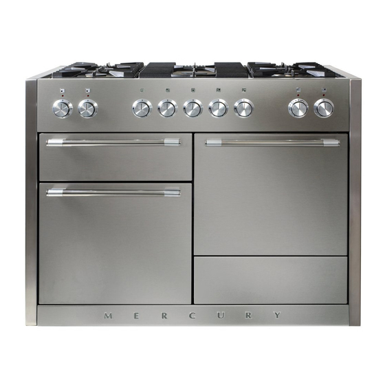
English 3. Cooker Overview DocAUS.020-0004 - Overview - 110DF - Elan Fig.3-1 The 1200 dual fuel cooker (Fig.3-1) has the following features: Fig.3-2 5 hotplate burners including a multi-ring burner A control panel A glide-out grill Main multi-function oven Fan oven Storage drawer Hotplate Burners The drawing by each of the control knobs indicates which... -
Page 8: Multi-Ring Centre Burner
English If, when you let go of the control knob the burner goes out, Fig.3-3 then the FSD has not been bypassed. Turn the control knob to the OFF position and wait for one minute before you try again, this time making sure to hold in the control knob for slightly longer. -
Page 9: Griddle (Optional Extra)
English Griddle (Optional extra) Fig.3-11 The griddle ts over the left-hand pan supports, front to back (Fig.3-11). It is designed for cooking food on directly. DO NOT use pans of any kind on it. The griddle surface is non-stick and metal cooking utensils (e.g. -
Page 10: Ovens
English Ovens Fan oven cooking is particularly suitable for baking on several shelves at one time and is a good ‘all-round’ function. It may References to ‘left-hand’ and ‘right-hand’ ovens apply as viewed be necessary to reduce the temperature by approximately from the front of the appliance. - Page 11 English Browning Element Function This function uses the element in the top of the oven To thaw small items in the oven without Defrost only. It is a useful function for the browning or heat nishing of pasta dishes, vegetables in sauce, A full cooking function, even heat shepherds pie and lasagne, the item to be browned being Fan oven...
-
Page 12: Accessories
English Accessories Fig.3-20 Fig.3-21 Oven Shelves The cooker is supplied with the following: 3 standard shelves (Fig.3-20) 1 drop shelf (Fig.3-21) 1 telescopic shelf with runners (Fig.3-22) 2 sets of side supports (Fig.3-23) The oven shelves are retained when pulled forward but can Fig.3-22 Fig.3-23 be easily removed and re tted. - Page 13 English To Fit the Telescopic Shelf Runners Fig.3-24 With the runner arm in the closed position locate the opening of the upper rear slot onto the side support (Fig.3-24). Do not locate any further than the opening at this point. Lift the front of the runner arm to locate the front slot against the side support (Fig.3-24).
-
Page 14: Storage
English Storage Fig.3-30 The bottom drawer is for storing oven trays and other cooking utensils. To open, simply push the drawer in and release. It can get very warm, so do not store anything in it that may melt or catch re. Never store ammable materials in the drawer. -
Page 15: Cooking Tips
English 4. Cooking Tips Cooking with a Multi-function Oven General Oven Tips Remember: not all modes are suitable for all food types. The The wire shelves should always be pushed rmly to the back oven cooking times given are intended for a guide only. of the oven. -
Page 16: Cooking Table
English 5. Cooking Table DocNo.031-0004 - Cooking table - electric & fan single cavity The oven control settings and cooking times given in the table below are intended to be used Top (T) AS A GUIDE ONLY. Individual tastes may require the temperature to be altered to provide a preferred result. -
Page 17: Cleaning Your Cooker Essential Information
English 6. Cleaning Your Cooker Essential Information Fig.6-1 Isolate the electricity supply before carrying out any thorough cleaning. Allow the cooker to cool. NEVER use paint solvents, washing soda, caustic ArtNo.311-0028 - Burner head off cleaners, biological powders, bleach, chlorine based bleach cleaners, coarse abrasives or salt. -
Page 18: Stainless Steel Main Top
English The Multi-ring Centre Burner Fig.6-4 The multi-ring burner can also be taken apart for cleaning. To Remove the Multi-ring Centre Burner To clean the multi-ring burner (Fig.6-4) you need to remove both the smaller inner cap and the larger outer cap. Next, lift o the inner brass ame ring, alongside the outer brass ame ring. -
Page 19: Control Panel And Oven Doors
English For safety, push the grill tray back into the grill chamber. Fig.6-7 If you need to remove the telescopic runners to allow cleaning of the grill chamber, rst remove the grill tray then you can unhook them from the grill chamber sides (Fig.6-8). Grill pan Wipe the sides clean with a soft cloth and mild detergent. -
Page 20: Cleaning Table
English Cleaning Table Fig.6-11 Cleaners listed (Table 6-1) are available from supermarkets or electrical retailers as stated. For enamelled surfaces use a cleaner that is approved for use on vitreous enamel. Regular cleaning is recommended. For easier cleaning, wipe up any spillages immediately. Hotplate Part Finish... -
Page 21: Troubleshooting
English 7. Troubleshooting Hotplate ignition or cooktop burners faulty We do not recommend corrosive or caustic cleaners as these may damage your cooker. Is the power on? Are the sparker (ignition electrode) or burner holes The knobs get hot when I use the oven, can I avoid this? blocked by debris? Yes, this is caused by heat rising from the oven, and heating them up. - Page 22 English Oven not coming on Fig.7-1 Is the power on? If not there may be something wrong with the power supply. Is the cooker supply on at the circuit breaker? Have you set a cooking function? Oven temperature getting hotter as the cooker gets older ArtNo.320-0006b -Mercury oven door hinge adjustment If turning the knob down has not worked or only worked for a short time then you may need a new...
-
Page 23: Installation
INSTALLATION Check the appliance is electrically safe and gas sound when you have nished. 8. Installation Dear Installer Provision of Ventilation Before you start your installation, please complete the details This appliance is not connected to a combustion products below, so that, if your customer has a problem relating to evacuation device. - Page 24 INSTALLATION Check the appliance is electrically safe and gas sound when you have nished. You will also need the following tools: The cooker is supplied with a stability chain, a flexible gas hose (attached to the cooker) and a wall connector bracket. Electric drill You will need the following equipment to complete the Masonry drill bit (only required if tting the cooker on a...
-
Page 25: Fitting The Wall Connector
INSTALLATION Check the appliance is electrically safe and gas sound when you have nished. Fitting the Wall Connector Fig.8-1 The wall connector needs to be tted prior to the installation of your cooker. The wall connector must be positioned in the Wall behind cooker shaded grey area shown in Fig.8-1, in order to secure a safe Wall connector location... -
Page 26: Moving The Cooker
INSTALLATION Check the appliance is electrically safe and gas sound when you have nished. Moving the Cooker Fig.8-4 On no account try and move the cooker while it is 1190 mm minimum* plugged into the electricity supply. (*check cookerhood instructions for actual dimensions) The cooker is very heavy, so take great care. -
Page 27: Conversion To Another Gas
INSTALLATION Check the appliance is electrically safe and gas sound when you have nished. Fitting the Vent Fig.8-9 The larger of the holes along the sides are for screwdriver access and should face to the rear (Fig.8-10). Use the screws and nuts supplied to hold the vent in place. - Page 28 INSTALLATION Check the appliance is electrically safe and gas sound when you have nished. Fig.8-14 Fig.8-13 1. Rear tab 4. Rear slotted tab 3. Front tab Fig.8-15 Locating slot 2. Locating slot Bracket Fig.8-16 Fig.8-17 Fig.8-19 Gasket* Fig.8-18...
-
Page 29: Fitting The Stability Chain
INSTALLATION Check the appliance is electrically safe and gas sound when you have nished. Fitting the Stability Chain Fig.8-20 Unless otherwise stated, a cooker using a exible gas connector must be secured with a suitable stability device. When using a stability chain (Fig.8-21) the chain should be kept as short as is practicable and xed rmly to the rear of the cooker, and to the wall with the supplied hook (Fig.8-22). -
Page 30: Pressure Testing
INSTALLATION Check the appliance is electrically safe and gas sound when you have nished. Gas Connection Fig.8-25 This must be in accordance with the relevant standards. The connector is located just below the hotplate level at the rear of the cooker. If in doubt contact your supplier. The rear cover boxes limit the position of the supply point. -
Page 31: Electrical Connection
INSTALLATION Check the appliance is electrically safe and gas sound when you have nished. Electrical Connection Fig.8-28 The cooker must be installed by a quali ed electrician, in accordance with the relevant national and local regulations. Current Operated Earth Leakage Breakers The combined use of your cooker and other domestic appliances may cause nuisance tripping, so we recommend that the cooker is protected on an individual... -
Page 32: Final Fitting
INSTALLATION Check the appliance is electrically safe and gas sound when you have nished. Final Fitting Fig.8-30 Fitting the Bottom Panel Open the left-hand oven door and make sure the storage drawer is removed. Note: For safety reasons make sure the drawer runners are out of the way. -
Page 33: Conversion To Lp Gas
WARNING – SERVICING TO BE CARRIED OUT ONLY BY AN AUTHORISED PERSON Disconnect from electricity and gas before servicing. Check appliance is safe when you have nished. 9. Conversion to LP Gas Check the ‘Technical Data’ section at the back of the book Fig.9-1 that the hob is convertible to the gas you want to use. - Page 34 WARNING – SERVICING TO BE CARRIED OUT ONLY BY AN AUTHORISED PERSON Disconnect from electricity and gas before servicing. Check appliance is safe when you have nished. Tap Adjustment Fig.9-3 Note: The valves in this cooker are tted with adjustable bypass screws to enable the turn-down rate to be set.
-
Page 35: Stick On Label
WARNING – SERVICING TO BE CARRIED OUT ONLY BY AN AUTHORISED PERSON Disconnect from electricity and gas before servicing. Check appliance is safe when you have nished. Stick on Label Fig.9-7 Stick the appropriate label on to the data badge to indicate the gas the appliance is now set for. -
Page 36: Circuit Diagram
English 10. Circuit Diagram P095199 P095199 P028728 br b The connections shown in the circuit diagram are for single-phase. The ratings are for 230 V 50 Hz. Code Description Code Description Code Colour Left-hand multi-function oven thermostat Right-hand fan oven control switch Blue Left-hand multi-function oven control switch Right-hand fan oven thermostat... -
Page 37: Technical Data
English 11. Technical Data ArtNo.105-0008 - Technical data - 90 induction - Elan THE COOKER IS CATEGORY: Natural Gas 12 T 2000 Pa. A conversion kit from Natural Gas to LPG 20 Y 2800 Pa, is packed with the cooker. INSTALLER: Please leave these instructions with the User. - Page 38 Notes...
- Page 39 Notes...
- Page 40 DocNo.000-0001 - Back cover Rangemaster Tel: 400-888-6288 Fax: 0760-22264283 E-mail: vatti@vatti.com.cn...
Need help?
Do you have a question about the MCY 1200 Dual Fuel and is the answer not in the manual?
Questions and answers