Rangemaster Excel 110 G5 Induction User's Manual & Installation Instructions
Range cooker
Hide thumbs
Also See for Excel 110 G5 Induction:
- User manual (44 pages) ,
- User's manual & installation instructions (48 pages)

Subscribe to Our Youtube Channel
Related Manuals for Rangemaster Excel 110 G5 Induction


Summary of Contents for Rangemaster Excel 110 G5 Induction
-
Page 1: Installation Instructions
Britain’s No.1 Range Cooker USER GUIDE & INSTALLATION INSTRUCTIONS Excel 110 G5 Induction... - Page 2 CUSTOMER SERVICES GUARANTEE STANDARDS Rangemaster range cookers come with a 1 year parts & labour Rangemaster cookers are designed and manufactured to a guarantee. You will receive an additional FREE full 12 months recognised international quality standard, which meets the...
-
Page 3: Table Of Contents
Tips on Cooking with the Timer Circuit Diagram: Oven General Oven Tips Technical Data Cooking Table Connections Cleaning Your Cooker Dimensions Essential Information Ratings Hotplate Efficiency Data Glide-out Grill Oven Data Control Panel and Doors Ovens Cleaning Table Excel 110 G5 Induction U110175-04... -
Page 5: Before You Start
1. Before You Start... Ventilation Your cooker should give you many years of trouble-free cooking if installed and operated correctly. It is important CAUTION: The use of a cooking appliance results in that you read this section before you start, particularly if you the production of heat and moisture in the room in have not used an induction cooker before. - Page 6 Always be certain that the controls are in the OFF position Fig. 1-1 when the oven is not in use, and before attempting to clean the cooker. Take care when touching the marked cooking areas of the hob. When the oven is on, DO NOT leave the oven door open for longer than necessary, otherwise the ArtNo.324-0001 Steam burst control knobs may become very hot.
-
Page 7: Hob Care
DO NOT use water on grease fires and never pick Fig. 1-3 up a flaming pan. Turn off the controls and then smother a flaming pan on a surface unit by covering the pan completely with a well fitting lid or baking tray. -
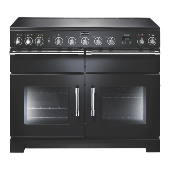
Page 8: Cooker Overview
2. Cooker Overview DocNo.025-0012 - Overview - 110 ceramic - Elan Fig. 2.1 Your induction cooker (Fig.2-1) has the following features: Fig. 2.2 5 induction cooking zones Control panel Glide-out grill Slow cook oven Programmable multifunction oven Fan oven The Hob Use only pans that are suitable for induction hobs. - Page 9 The very best pans have bases that are very slightly curved Fig. 2.4 up when cold (Fig.2-3). If you hold a ruler across the bottom you will see a small gap in the middle. When they heat up the Max: 1.85 kW Max: 1.85 kW Max: 1.85 kW metal expands and lies flat on the cooking surface.
- Page 10 Residual Heat Indicator, H Automatic Heat-up Time at Power Level 100% (min:sec) After use, a cooking zone will remain hot for a while as heat dissipates. When a cooking zone is switched off the residual 0:48 heat indicator symbol [H ], will appear in the display. This 2:24 shows that the cooking zone temperature is above 60 °C and may still cause burns.
- Page 11 Low Temperature Setting, L1/L2 Fig. 2.8 A & B linked Each cooking area is equipped with 2 low temperature settings: L1 will maintain a temperature of about 40 °C – ideal for • gently melting butter or chocolate. L2 will maintain a temperature of about 90 °C – ideal for •...
-
Page 12: The Glide-Out Grill
The Glide-out Grill Fig. 2.9 CAUTION: This appliance is for cooking purposes only. It must not be used for other purposes, for example room heating. CAUTION: Accessible parts may be hot when the grill is in use. Young children should be kept away. Open the door and pull the grill pan carriage forward using the handle (Fig.2-9). -
Page 13: The Ovens
The Ovens Fan Oven This function operates the fan and the heating The clock must be set to the time of day before the left- element around it. An even heat is produced hand oven will work. See the following section on ‘The throughout the oven, allowing you to cook large Clock’... -
Page 14: The Slow Cook Oven
Conventional Oven (Top and Base Heat) The Fan Oven This function combines the heat from the top and Fan ovens circulate hot air continuously, which means base elements. It is particularly suitable for roasting faster, more even cooking. The recommended cooking and baking pastry, cakes and biscuits. - Page 15 Operating the Ovens Fig. 2.12 Fan Oven Turn the oven knob to the desired temperature (Fig. 2.12). The oven indicator light will glow until the oven has reached the temperature selected. It will then cycle on and off during cooking. Multifunction Oven The multifunction oven has two controls: a function selector and a temperature setting knob (Fig.
-
Page 16: The Clock
The Clock Fig. 2.16 The clock must be set to the time of day before the oven ArtNo.300-0005 2BC will work. minute minder setting 1. Once the cooker is connected and switched on, the display will start to flash. 2. To set the time, turn and hold the Timer (A) knob to the Clock (C) setting and at the same time turn the Adjusting (B) knob either clockwise or counter-clockwise (Fig. - Page 17 To Stop the Multifunction Oven at a Specific ArtNo.301-0008 2BC Fig. 2.21 Stopping the oven 2 Time of Day You have set the required temperature and function mode for the Multifunction Oven and you would like the Multifunction Oven to automatically stop. TOP TIP Make a note of the current time so you do not forget.
- Page 18 To Start and Stop the Multifunction Oven ArtNo.301-0010 2BC Fig. 2.24 Setting the cooking time The Multifunction Oven allows you to automatically start and stop by a combination of the length of the cooking time and the stop time. Giving you the flexibilty to cook casseroles etc while you are out.
-
Page 19: Accessories
Accessories Fig. 2.31 Oven Shelves – Left-hand (Main) Oven Shelf guard The oven shelves (Fig. 2.31) are retained when pulled forward but can be easily removed and refitted. Pull the shelf forward until the back of the shelf is stopped by the shelf stop bumps in the oven sides (Fig. -
Page 20: Cooking Tips
3. Cooking Tips WARNING! Refer to Before You Start... chapter. Hints on Using Your Induction Cooker General Oven Tips If you have not used an induction cooker before please be The wire shelves should always be pushed firmly to the back aware of the following: of the oven. -
Page 21: Cooking Table
4. Cooking Table DocNo.031-0004 - Cooking table - electric & fan single cavity The oven control settings and cooking times given in the table below are intended to be used Top (T) AS A GUIDE ONLY. Individual tastes may require the temperature to be altered to provide a ArtNo.050-0007 preferred result. -
Page 22: Cleaning Your Cooker
5. Cleaning Your Cooker DocNo.045-0017 - Cleaning - 110 Classic - tpl glzd & std grill Essential Information Fig. 5.1 Isolate the electricity supply before carrying out any major cleaning. Then allow the cooker to cool. NEVER use paint solvents, washing soda, caustic cleaners, biological powders, bleach, chlorine based bleach cleaners, coarse abrasives or salt. -
Page 23: Glide-Out Grill
Cleaning Burned-on Spills Fig. 5.2 Make sure that the heat indicator lights are off and that the hob is cool. Remove the excess burned-on substance with a single-edged razor scraper. Hold the scraper at an angle of about 30° to the surface and then scrape off the burned-on matter (Fig. -
Page 24: Control Panel And Doors
Control Panel and Doors Fig. 5.7 Avoid using any abrasive cleaners, including cream cleaners, on the control panel. For best results, use a liquid detergent. The same cleaner can also be used on the doors. Alternatively, use a soft cloth wrung out in clean hot soapy water. You can use the same method for cleaning the control panel and knobs. -
Page 25: Cleaning Table
Cleaning Table Cleaners listed (Table 5-1) are available from supermarkets or electrical retailers as stated. For enamelled surfaces use a cleaner that is approved for use on vitreous enamel. Regular cleaning is recommended. For easier cleaning, wipe up any spillages immediately. Hotplate Part Finish... -
Page 26: Troubleshooting
6. Troubleshooting DocNo.050-0001 - Troubleshooting - Induction GENERIC Interference with and repairs to the hob MUST NOT The cooling fan be carried out by unqualified persons. Do not try The induction hob incorporates a cooling fan. This to repair the hob as this may result in injury and cooling fan is active when either the grill or ovens damage to the hob. - Page 27 Food is cooking too slowly, too quickly, or burning Fig. 6-1 Cooking times may differ from your previous oven. Check that you are using the recommended temperatures and shelf positions – see the oven ArtNo.324-0005 Oven light bulb cooking guide. Then adjust the settings according to your own individual tastes.
- Page 28 The oven light is not working Fig. 6-3 The bulb has probably blown. You can buy a replacement bulb (which is not covered under the guarantee) from most electrical stores. Ask for an Edison screw fitting 15 W 230 V lamp, FOR OVENS (Fig.6-1). It must be a special bulb, heat resistant to 300 °C.
-
Page 29: Installation
INSTALLATION Check the appliance is electrically safe when you have finished. 7. Installation DocNo.066-0003 - Installation - 110 Ceramic - Excel Dear Installer You will need the following equipment to complete the cooker installation satisfactorily: Before you start your installation, please complete the details •... -
Page 30: Positioning The Cooker
INSTALLATION Check the appliance is electrically safe when you have finished. Positioning the Cooker Fig. 7.1 Fig.7-1 and Fig.7-2 show the minimum recommended distance from the cooker to nearby surfaces. 75 mm 75 mm 650 mm The cooker should not be placed on a base. The hotplate surround should be level with, or above, any adjacent work surface. -
Page 31: Repositioning The Cooker Following Connection
INSTALLATION Check the appliance is electrically safe when you have finished. Lowering the Two Rear Rollers Fig. 7.5 To adjust the height of the rear of the cooker, first fit a 13 mm spanner or socket wrench onto the hexagonal adjusting nut (Fig.7-5). -
Page 32: Electrical Connection
INSTALLATION Check the appliance is electrically safe when you have finished. Electrical Connection Current Operated Earth Leakage Breakers The combined use of your cooker and other domestic This appliance must be installed by a suitably qualified appliances may cause nuisance tripping, so we recommend electrician to comply with the relevant electrical regulations, that the cooker is protected on an individual RCD (Residual and also the local electricity supply company requirements. -
Page 33: Circuit Diagrams
8. Circuit Diagrams Circuit Diagram: Hob Earth N(6) On terminal block N(4) On terminal block Induction unit Hob display ArtNo.083-0011 - IN G5 2-phase - Circuit diagram L(2) L(3) On terminal block w/br Interface w/br w/br board w/br w/br The connections shown in the circuit diagram are for single-phase. The ratings are for 230 V 50 Hz. Code Description Code Colour w/br White/brown... -
Page 34: Circuit Diagram: Oven
Circuit Diagram: Oven P095199 P038434 P033458 P033458 The connections shown in the circuit diagram are for single-phase. The ratings are for 230 V 50 Hz. Code Description Code Description Code Colour Grill thermostat Slow cook oven thermostat Blue Grill elements Slow cook oven switch Brown Grill front switch... -
Page 35: Technical Data
DocNo.103-0019 - Technical data - 110 Induction - G5 Excel 9. Technical Data INSTALLER: Please leave these instructions with the user. DATA BADGE LOCATION: Cooker back, serial number repeater badge below the oven door opening. COUNTRY OF DESTINATION: GB, IE, FR, NL, DE, SE, BE, AT, CH, LU. Connections Electric 230 / 400 V ~ 50 Hz 3N... -
Page 36: Hotplate Efficiency Data
Hotplate Efficiency Data Brand Rangemaster Model Identification Excel Size Type Induction Type of Hob Induction Number of electric zones Zone 1 - Ø cm 18.5 Heating Technology Energy Consumption (ECElectric cooking) - Wh/kg Zone 2 - Ø cm 15.5 Heating Technology Energy Consumption (ECElectric cooking) - Wh/kg Zone 3 - Ø... -
Page 37: Oven Data
Oven Data Brand Rangemaster Model identification Excel Type of oven Electric Mass Number of cavities Left-hand Efficiency Fuel type Electric Cavity type Multifunction Power - conventional Power - forced air convection Volume Litres Energy consumption (electricity) - conventional kWh / cycle 1.08... - Page 38 Notes...
- Page 39 0800 804 6261 or depending on your mobile network tariff you can For a competitive quote and to arrange for a Rangemaster approved call free on 0370 789 5107. engineer to attend, call Consumer Services on: 0800 804 6261 or...
- Page 40 Registered in England and Wales. Registration No. 354715 Registered Office: Juno Drive, Leamington Spa, Warwickshire, CV31 3RG Rangemaster continuously seeks improvements in specification, design and production of products and thus, alterations take place peri- odically. Whilst every effort is made to produce up-to-date literature, this booklet should not be regarded as an infallible guide to current...
Need help?
Do you have a question about the Excel 110 G5 Induction and is the answer not in the manual?
Questions and answers