Dürkopp Adler 650-16 Operating Manual
Hide thumbs
Also See for 650-16:
- Operating instructions manual (134 pages) ,
- Operating instructions manual (150 pages)
Table of Contents
Advertisement
Quick Links
Advertisement
Table of Contents

Subscribe to Our Youtube Channel
Related Manuals for Dürkopp Adler 650-16


Summary of Contents for Dürkopp Adler 650-16
- Page 1 650-16 Operating Manual...
- Page 2 All rights reserved. Property of Dürkopp Adler AG and subject to copyright. Any use of this content, or parts of it, is prohibited without express prior permission from Dürkopp Adler AG. Copyright © Dürkopp Adler AG - 2013...
-
Page 3: Table Of Contents
Manual mode..................29 9.4.1 Quick access function (softkey menu)..........31 9.4.2 Menu for additional settings..............32 9.4.3 Sewing process ...................33 Automatic mode...................33 9.5.1 Before sewing..................34 9.5.2 Sewing process ...................36 9.5.3 Terminating a program ................37 Quick programming ................38 Operating manual 650-16 Version 00.0 - 07/2013... - Page 4 Connecting the knee switch ..............69 11.9.13 Connecting the control panel .............. 70 11.9.14 Connecting the LED sewing lamp ............71 11.9.15 Connecting the auxiliary sewing lamp (Waldmann - optional) .... 71 11.10 Sewing test..................72 Appendix.................... 73 Operating manual 650-16 Version 00.0 - 07/2013...
-
Page 5: General Information
1 General Information 1.1 Scope of this guide This guide describes the intended use and assembly of the special purpose sewing machine 650-16 for sewing sleeves. 1.2 Declaration of conformity The machine conforms with the European regulations stated in the declaration of conformity or incorporation. -
Page 6: Limited Liability
The manufacturer accepts no liability in case of damage due to: • failure to observe this guide • unintended use • unauthorized modifications to the machine • use of untrained staff • breakage and transport damage • use of non-approved spare parts Instruction manual 650-16 Version 00.0 - 07/2013... -
Page 7: Safety Instructions
In the following situations, always de-energize the machine at the main switch or by unplugging the mains plug: • Threading • Replacing the needle or other sewing tools • Leaving the workplace • Performing maintenance work and repairs Instruction manual 650-16 Version 00.0 - 07/2013... - Page 8 Work on live parts and assemblies is prohibited. Exceptions are governed by the regulations in DIN VDE 0105. Only use original spare parts by the manufacturer. Incorrect or faulty spare parts can impair safety and damage the machine. Instruction manual 650-16 Version 00.0 - 07/2013...
-
Page 9: Marking Of Safety Instructions
Attention: Risk of damage. In case of dangers for persons, these symbols indicate the type of danger: General danger Danger due to electric shock Danger due to pointed objects Danger due to crushing Instruction manual 650-16 Version 00.0 - 07/2013... - Page 10 CAUTION Type and source of danger Consequences in case of failure to observe Measures for preventing the danger Danger notice where failure to observe can lead to damage to property. Instruction manual 650-16 Version 00.0 - 07/2013...
-
Page 11: Environmental Protection Notes
Type and source of danger Consequences in case of failure to observe Measures for preventing the danger This is what environmental protection instructions for compliant disposal look like. Failure to observe can lead to environmental dam- age. Instruction manual 650-16 Version 00.0 - 07/2013... -
Page 12: Legend
Additional information, e. g. regarding alternative operating op- tions. Order States which work you must perform before or after the setting. References This is followed by a reference to another part of the text. Instruction manual 650-16 Version 00.0 - 07/2013... -
Page 13: Product Description
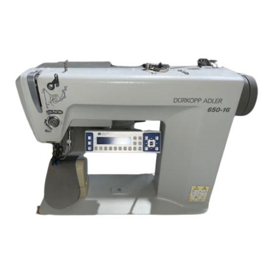
Product description 5 Product description The Dürkopp Adler 650-16 is a special purpose sewing machine for programmed or manual sewing in of sleeves in ladies and gents clothing. The sewing machine is equipped with an integrated sewing drive, a step-motor driven upper and lower belt transport for gentle feeding of the material, step-motor driven curve support and an sloping pedestal for improved material handling. - Page 14 On retrieving the next step, the gathering value stored in the program again applies. Alternatively, depending on the presetting at technician level, the curve radius can be changed in the same way. Instruction manual 650-16 Version 00.0 - 07/2013...
-
Page 15: Intended Use
Intended use 6 Intended use The 650-16 is a special purpose sewing machine that is intended for sewing light to medium-weight material. Such material is usu- ally composed of textile fibers. This material is used in the clothing industry. This special purpose sewing machine can also be used to produce so-called technical seams. -
Page 16: Technical Data
Width, depth, height [mm] 1320 / 750 / 1300 (machine resting on frame) Weight [kg] (machine resting on frame) Rated voltage[V/Hz] 190 – 240V 50/60Hz Rated voltage at factory setting[V/Hz] 1 x 230V 50Hz Power rating[kVA] Instruction manual 650-16 Version 00.0 - 07/2013... -
Page 17: Operation
Important: The unwinder arm must be horizontally above the thread bobbin. 2. Thread as shown in the following figure. Fig. 1: Threading the needle thread Stretching Fig. 2: Threading with stretching threads threads Instruction manual 650-16 Version 00.0 - 07/2013... -
Page 18: Adjusting The Needle-Thread Tension
1. Use the OP 3000 to set the main tensioner (1) so that a uniform stitch pattern is produced ( Chap. 9.4, p. 29). The main tensioner (1) is opened automatically when trimming Automatic opening the thread. Instruction manual 650-16 Version 00.0 - 07/2013... -
Page 19: Adjusting The Thread Regulator
Fig. 5: Adjusting the thread regulator (1) - Screw (3) - Thread tensioning spring (2) Thread regulator Steps 1. Release the screw (1). 2. Adjust the position of the thread regulator (2). 3. Tighten the screw (1). Instruction manual 650-16 Version 00.0 - 07/2013... -
Page 20: Winding On The Hook Thread
6. Start sewing. 7. After reaching the set bobbin fill quantity, the bobbin winder switches off automatically ( Service Manual Chap. 16.1). 8. Remove the full bobbin, clamp the thread under blade (3) and cut. Instruction manual 650-16 Version 00.0 - 07/2013... -
Page 21: Changing The Hook Thread Bobbin
3. Pull approx. 5 cm of hook thread out of the bobbin case (7). 4. When pulling the thread, the bobbin should must in the direc- tion indicated by the arrow. 5. Reinsert the bobbin case (7). 6. Slide the hook cover (2) upwards. Instruction manual 650-16 Version 00.0 - 07/2013... -
Page 22: Adjusting The Hook Thread Tension
The basic setting for the tension spring is as follows: The bobbin casing must slowly drop due to its own mass with a full bobbin. Fig. 8: Bobbin casing dropping The brake spring prevents the bobbin running on when trimming the thread. Instruction manual 650-16 Version 00.0 - 07/2013... - Page 23 8. Pull the hook thread in the direction of sewing at an angle of 45°. You should feel about half the tension value. 9. Then tighten the adjusting screw (3) until the recommended tension value is produced. Instruction manual 650-16 Version 00.0 - 07/2013...
-
Page 24: Changing Needles
An incorrect hook clearance can cause the following problems: • Changing to a thinner needle: Missing stitches Damage to the thread • Changing to a thicker needle:Damage to the hook tip Damage to the needle Instruction manual 650-16 Version 00.0 - 07/2013... -
Page 25: Lifting The Sewing Feet
(2)- Additional pedal (optional) (3) - Foot pedal Steps 1. Depress the pedal backwards half-way. 2. The sewing feet lift. 1. Fully depress the pedal backwards. 2. Activates the thread trim and lifts sewing feet. Instruction manual 650-16 Version 00.0 - 07/2013... -
Page 26: Function Of The Optional Additional Pedal
The knee switch (1) switches from one step to the next in the sewing programs both in automatic mode and programming mode. Fig. 12: Knee switch (1) - Knee switch Steps 1. Press the knee switch. The next program step is called up. Instruction manual 650-16 Version 00.0 - 07/2013... -
Page 27: Sewing
The threads are cut (if activated). The machine stops in the 2nd position. The needle is up. The sewing feet lifted. • Remove the material. • Release the pedal. The sewing feet are lowered. Instruction manual 650-16 Version 00.0 - 07/2013... -
Page 28: Operating And Programming The Control Unit
Operating and programming the control unit 9 Operating and programming the control unit 9.1 Control panel OP3000 Fig. 13: Control panel on control unit All settings for the control unit on the 650-16 are made at OP3000 control panel. Button Function... -
Page 29: Switching On The Sewing Machine
The display shows the last program to be use ( Fig. 15) or manual mode ( Fig. 16). Fig. 15: Displaying the last program to be used Fig. 16: Display in manual mode Instruction manual 650-16 Version 00.0 - 07/2013... -
Page 30: Operating Modes Of The Control Unit
Operating and programming the control unit 9.3 Operating modes of the control unit The 650-16 control unit features 4 different operating modes: • Manual mode (Program 000) Manual mode is the simplest operating mode. There are no sewing programs and no entries for individual sewing steps. -
Page 31: Manual Mode
• Select the desired fullness value using buttons "0" to "16". • Press the "+/-" button to select fullness top or fullness bottom. • Select the fullness value by using the second pedal, if set. Instruction manual 650-16 Version 00.0 - 07/2013... - Page 32 Creating a program( Chap. 9.8.1, p. 45) Changing between fullness top and fullness bottom ESC, F and S No function 0 – 16 Fullness values No function Instruction manual 650-16 Version 00.0 - 07/2013...
-
Page 33: Quick Access Function (Softkey Menu)
When stopping in the seam the needle is up or down. Automatic step change On / Off (Only available in the automatic mode) • Press button "4". Automatic step change is switched on or off when sewing a seam. Instruction manual 650-16 Version 00.0 - 07/2013... -
Page 34: Menu For Additional Settings
Foot Press. (sewing foot pressure) Value range: 1 - 15 Start tack (tack at start of seam) Value range: on/off End tack (tack at end of seam) Value range: on/off Thread trim Value range: on/off Instruction manual 650-16 Version 00.0 - 07/2013... -
Page 35: Sewing Process
The control unit switches to automatic mode and the fol- lowing appears in the display. Fig. 19: Display in automatic mode The following table explains the individual symbols in the display and the functions of the buttons on the control panel. Instruction manual 650-16 Version 00.0 - 07/2013... -
Page 36: Before Sewing
The thread tension can be changed before tacking on. The change applies to the entire sewing program. Press to select the "Thread tension" parameter. • Change the thread tension using buttons " " and " ". Instruction manual 650-16 Version 00.0 - 07/2013... - Page 37 (-) if there is no auto- matic step change Programming mode Switches to the programming mode No function ESC, F, S 1. Sew, actuate the knee switch or press "OK". The machine switches to the 1st step. Instruction manual 650-16 Version 00.0 - 07/2013...
-
Page 38: Sewing Process
Half of the current step is bolded in the program bar. Fig. 21: Step in processing Processed steps are indicated by a bolded bar. Fig. 22: Fully processed step Instruction manual 650-16 Version 00.0 - 07/2013... -
Page 39: Terminating A Program
Lower softkey Softkey menu Chap. 9.4 Manual Mode, p. 29) 9.5.3 Terminating a program 1. Trim (pedal fully depressed). 2. Tap "ESC". Push the pedal fully back The program is canceled. Instruction manual 650-16 Version 00.0 - 07/2013... -
Page 40: Quick Programming
or numeric key 0 – 9 to select the program number. 4. Press "OK". The following appears in the display. The "P" in the field for the program number flashes. Fig. 25: Display Quick programming Instruction manual 650-16 Version 00.0 - 07/2013... - Page 41 Value range: 0 to 6 • Press " " and " " to select the "Curve support" parameter. • Press " " to change the curve support. Length of the current step in mm Instruction manual 650-16 Version 00.0 - 07/2013...
-
Page 42: Programming Via Keypad Input
• the selection screen for the action for creating the 2nd sleeve side is opened The machine changes to automatic mode. The newly created program is selected. Fig. 26: Displaying the newly created program Instruction manual 650-16 Version 00.0 - 07/2013... -
Page 43: Programming By Sewing
Depending on the setting at technician level, the created sleeve side is mirrored. The machine switches to automatic mode. The newly created program is selected. Fig. 28: Displaying the newly created program Instruction manual 650-16 Version 00.0 - 07/2013... -
Page 44: Editing Mode
The selected step is shown bolded in the program bar. 2. Press to select the parameters to be changed for the selected step, and then press to change them. Instruction manual 650-16 Version 00.0 - 07/2013... -
Page 45: Changing Other Parameters For The Current Step
4. Press "OK" to enable or disable the parameters, or press to change the value, and "OK" to confirm. Symbol Meaning Step. Len. Auto Forward Alternate Foot Press 5. Press "ESC" or to quit the submenu. Instruction manual 650-16 Version 00.0 - 07/2013... -
Page 46: Changing Other Parameters For The Selected Program
to change the value, and "OK" to confirm. Symbol Meaning Thr. Tens Stitchlen. Stitch length Foot Press. (sewing foot pressure) Fulln. Corr. Start Tack End Tack Thread trim 5. Press "ESC" or to quit the submenu. Instruction manual 650-16 Version 00.0 - 07/2013... -
Page 47: Programming Mode
The program number is applied. The following is displayed; "P" flashes. Fig. 32: Display after defining the program number 4. Change the sleeve side or other parameters if necessary ( Chap. 9.7 Editing mode, p. 42). Instruction manual 650-16 Version 00.0 - 07/2013... - Page 48 Fig. 34: Prompt after creating a program 8. Select whether • to mirror the sleeve side you created • not to mirror the sleeve side you created • to open the teach-in for the 2nd sleeve side Instruction manual 650-16 Version 00.0 - 07/2013...
-
Page 49: Copying A Program
Fig. 37: Display after defining the program number 4. Make any required changes to the new program. 5. Press "ESC". The programming mode is ended and the machine switches to the automatic mode. Instruction manual 650-16 Version 00.0 - 07/2013... -
Page 50: Deleting A Program
1. Press the button. The softkey menu appears. Fig. 39: Softkey menu 2. Press the button. 3. Press "ESC". The programming mode is ended and the machine switches to the automatic mode. Instruction manual 650-16 Version 00.0 - 07/2013... -
Page 51: Maintenance
• Bobbin casing and interior • Thread trimmer • Area around the needle Direct drive • Clean the motor fan filter of sewing • Clean the motor fan dust (e.g. with a compressed air gun) screen (3) Instruction manual 650-16 Version 00.0 - 07/2013... -
Page 52: Installation
11.1 Scope of delivery The items supplied depend on your order. Before setting up the machine please check to make sure all of the required parts are present. Fig. 41: Scope of delivery Instruction manual 650-16 Version 00.0 - 07/2013... -
Page 53: Removing The Security Devices
If the special purpose sewing machine you have bought is already set up, the following transport packing must be removed: • Safety straps and battens on the machine head, table top and frame. • Safety block and straps on the sewing drive. Instruction manual 650-16 Version 00.0 - 07/2013... -
Page 54: Assembling The Stand
6. Screw the cable duct (6) (30 x 30 x 250 mm) for the encoder onto the frame strut (5). 7. Turn adjusting screw (8) to ensure the stability of the frame. The frame must rest with all four feet flush on the floor. Instruction manual 650-16 Version 00.0 - 07/2013... -
Page 55: Pre-Assembling The Table Top
3.5 x 17). 11. Fit the electrical cables( Chap. 11.9 Electrical connections, p. 58) A larger scale illustration is available at the end of the manual ( Chap. 12 Appendix, p. 73). Instruction manual 650-16 Version 00.0 - 07/2013... -
Page 56: Attaching The Table Top And The Pedals To The Frame
9. Insert the reel stand (1) into the drilled hole in the table top and secure in place with a nut and washer. 10. Mount and align the reel holder and unwinder arm. Important: The reel holder and unwinder arm must be verti- cally aligned. Instruction manual 650-16 Version 00.0 - 07/2013... -
Page 57: Completing The Table Top
3. Fasten the bracket supports (3) with screws 4.5 x 15 (4x). 4. Fasten the rails (4) to the table top using screws 4.5 x 55 (8x). 5. Insert the machine head support (2). Instruction manual 650-16 Version 00.0 - 07/2013... -
Page 58: Adjusting The Working Height
1. Undo the screws (1) on the frame braces. 2. Adjust the table top horizontally to the required working height. 3. To avoid tilting, pull out, or push in, the table top evenly on both sides. 4. Tighten the screws (1). Instruction manual 650-16 Version 00.0 - 07/2013... -
Page 59: Inserting The Machine Head
For machines delivered pre-assembled, the transport lug is in the accessory pack. WARNING Risk of injury due to the machine head tipping Secure the machine head against tipping when transporting the assembled machine. Instruction manual 650-16 Version 00.0 - 07/2013... -
Page 60: Electrical Connections
The voltage stated on the sewing drive type plate must match the mains voltage. DANGER Danger of fatal injury due to electric shock Make sure that the voltage stated on the sewing drive type plate matches the mains voltage. Instruction manual 650-16 Version 00.0 - 07/2013... -
Page 61: Mains Voltage Distribution
9. Refit the cover (3) on the main switch. 10. Refit and fasten the rotatable switch (1). 11. Fit the cable duct cover to the cable duct. Instruction manual 650-16 Version 00.0 - 07/2013... -
Page 62: Connecting The Lines For The Machine Head
(2). 3. Attach the remaining cables to the correspondingly labeled connectors on connection side (1). 4. Connect the LED lamp to the transformer.( Chap. 11.9.14 Connecting the LED sewing lamp, p. 71) Instruction manual 650-16 Version 00.0 - 07/2013... -
Page 63: Connecting Auxiliary Control Unit Cables
2 ( Fig. 49: Connecting the lines for the machine head, p. 60). 2. Route the cable (1) for the stepper motor into the underside of the housing (2) and plug it into the connecting plug. Instruction manual 650-16 Version 00.0 - 07/2013... -
Page 64: Connecting The Encoder To The Control Unit
Fig. 51: Connecting the encoder to the control unit Steps 1. Connect the encoder for the main pedal to the "Speed" con- nector (1) (X120b). 2. Connect the encoder for the additional pedal to the "Fullness" connector (2) (X120t). Instruction manual 650-16 Version 00.0 - 07/2013... -
Page 65: Establishing Equipotential Bonding For The Machine Head
(3) - Blade connector (2) - Earthing cable Steps 1. Screw the earthing cable (2) to the machine head (1); route it to the auxiliary control box and connect it to the blade connector (3). Instruction manual 650-16 Version 00.0 - 07/2013... -
Page 66: Establishing Equipotential Bonding For The Control Unit
(3) - Earthing cable Steps 1. Fasten the earthing cable (3) from the connector (2) onto the control box (1). 2. Screw the earthing cable (4) (150 mm) with toothed washer onto the frame (5). Instruction manual 650-16 Version 00.0 - 07/2013... -
Page 67: Establishing Equipotential Bonding For The Auxiliary Control Unit
(2) - Blade connector Steps 1. Attach the earthing cable (1) to the flat plug (2) on the auxiliary control box. 2. Route cable (2) (300 mm) to control box (3) and screw in place. Instruction manual 650-16 Version 00.0 - 07/2013... -
Page 68: Establishing Equipotential Bonding For The Sewing Drive
The earthing cable (2) for the sewing motor is connected to con- nector (3) for the sewing drive. Steps 1. Attach the earthing cable (2) to the earthing point on the control box (1). Instruction manual 650-16 Version 00.0 - 07/2013... -
Page 69: Establishing Equipotential Bonding For The Knee Switch
1. Attach the earthing cable (3) (650 mm) to the fastening clip (1) on the knee switch. 2. Route the cable through cable duct (2) and then connect it to the blade connector (4) on the auxiliary control unit. Instruction manual 650-16 Version 00.0 - 07/2013... -
Page 70: Establishing Equipotential Bonding For Encoders
2. Route the cable (4) through the cable duct (3) to the encoder (2) and screw in place (optional). 3. Attach the earthing cable (1, 650 mm) to the encoder (2) and the control box (6). Instruction manual 650-16 Version 00.0 - 07/2013... -
Page 71: Connecting The Knee Switch
(3) - Knee switch (2) - Cable Steps 1. Route the cable (2) from the knee switch (3) through the cable duct to the control unit and connect it to the connector (1). Instruction manual 650-16 Version 00.0 - 07/2013... -
Page 72: Connecting The Control Panel
2. Attach the connector on the cable (1) to the control panel; route the cable through the table top opening (2) to the control box and connect it to the socket (X170 panel). Instruction manual 650-16 Version 00.0 - 07/2013... -
Page 73: Connecting The Led Sewing Lamp
3. Connect the plug (3) on the LED lamp to the black connector on the sewing lamp controller. 11.9.15 Connecting the auxiliary sewing lamp (Wald- mann - optional) See installation instructions 0791 100702. These instructions are supplied with the sewing lamp. Instruction manual 650-16 Version 00.0 - 07/2013... -
Page 74: Sewing Test
12. If requirements are not met, change the thread tensions ( Chap. 8.2, p. 16) and ( Chap. 8.6, p. 20). If necessary, also check the settings specified in the service manual and correct where applicable. Instruction manual 650-16 Version 00.0 - 07/2013... -
Page 75: Appendix
Appendix 12 Appendix Dimensions for making a table top Instruction manual 650-16 Version 00.0 - 07/2013... - Page 76 Appendix Instruction manual 650-16 Version 00.0 - 07/2013...
- Page 77 Appendix Instruction manual 650-16 Version 00.0 - 07/2013...
- Page 78 Appendix Instruction manual 650-16 Version 00.0 - 07/2013...
- Page 80 DÜRKOPP ADLER AG Potsdamer Str. 190 33719 Bielefeld Germany Phone +49 (0) 521 925 00 E-Mail: service@duerkopp-adler.com...
Need help?
Do you have a question about the 650-16 and is the answer not in the manual?
Questions and answers