DURKOPP ADLER 650-16 Operating Instructions Manual
Hide thumbs
Also See for 650-16:
- Operating instructions manual (134 pages) ,
- Operating manual (80 pages)
Table of Contents
Advertisement
Quick Links
Advertisement
Table of Contents

Subscribe to Our Youtube Channel
Related Manuals for DURKOPP ADLER 650-16


Summary of Contents for DURKOPP ADLER 650-16
- Page 1 650-16 Operating Instructions...
- Page 2 IMPORTANT READ CAREFULLY BEFORE USE KEEP FOR FUTURE REFERENCE All rights reserved. Property of Dürkopp Adler AG and protected by copyright. Any reuse of these contents, including extracts, is prohibited without the prior written approval of Dürkopp Adler AG. Copyright © Dürkopp Adler AG 2016...
-
Page 3: Table Of Contents
Sewing process ................... 44 Automatic mode .................. 45 Before starting sewing ................. 46 5.5.1 5.5.2 Sewing....................47 5.5.3 Canceling the program ................ 49 Quick programming ................49 5.6.1 Creating a program by keyboard input ..........52 Operating Instructions 650-16 - 02.0 - 08/2016... - Page 4 Assembling the frame................ 110 Pre-assembling the table top............. 111 Attaching the table top and pedals to the frame ........ 113 Setting the working height ..............115 Inserting the machine upper part............117 Electrical connection ................. 118 Operating Instructions 650-16 - 02.0 - 08/2016...
- Page 5 8.10 Sewing test ..................132 Decommissioning ................133 Disposal ................... 135 Troubleshooting ................137 11.1 Customer service ................137 11.2 Errors in sewing process ..............138 Technical Data ................. 141 Appendix ..................143 Operating Instructions 650-16 - 02.0 - 08/2016...
- Page 6 Table of Contents Operating Instructions 650-16 - 02.0 - 08/2016...
-
Page 7: About These Instructions
Representation conventions – symbols and characters Various information in these instructions is represented or high- lighted by the following characters in order to facilitate easy and quick understanding: Proper setting Specifies proper setting. Operating Instructions 650-16 - 02.0 - 08/2016... - Page 8 Important Special attention must be paid to this point when performing a step. Information Additional information, e.g. on alternative operating options. Order Specifies the work to be performed before or after a setting. Operating Instructions 650-16 - 02.0 - 08/2016...
-
Page 9: Other Documents
Dürkopp Adler cannot be held liable for any damage resulting from: • Breakage and damage during transport • Failure to observe these instructions • Improper use • Unauthorized modifications to the machine • Use of untrained personnel • Use of unapproved parts Operating Instructions 650-16 - 02.0 - 08/2016... - Page 10 Leave machines, equipment and packaging material in the con- dition in which they were found when the damage was discovered. This will ensure any claims against the transport company. Report all other complaints to Dürkopp Adler immediately after receiving the product. Operating Instructions 650-16 - 02.0 - 08/2016...
-
Page 11: Safety
Obligations Follow the country-specific safety and accident prevention regu- of the operator lations and the legal regulations concerning industrial safety and the protection of the environment. Operating Instructions 650-16 - 02.0 - 08/2016... -
Page 12: Signal Words And Symbols Used In Warnings
Signal words Signal words and the hazard they describe: Signal word Meaning DANGER (with hazard symbol) If ignored, fatal or serious injury will result WARNING (with hazard symbol) If ignored, fatal or serious injury can result Operating Instructions 650-16 - 02.0 - 08/2016... - Page 13 If ignored, environmental damage can result NOTICE (without hazard symbol) If ignored, property damage can result Symbols The following symbols indicate the type of danger to personnel: Symbol Type of danger General Electric shock Puncture Crushing Environmental damage Operating Instructions 650-16 - 02.0 - 08/2016...
- Page 14 Type and source of danger! Consequences of non-compliance. Measures for avoiding the danger. This is what a warning looks like for a hazard that could result in moderate or minor injury if the warning is ignored. Operating Instructions 650-16 - 02.0 - 08/2016...
- Page 15 CAUTION Type and source of danger! Consequences of non-compliance. Measures for avoiding the danger. This is what a warning looks like for a hazard that could result in environmental damage if ignored. Operating Instructions 650-16 - 02.0 - 08/2016...
- Page 16 Safety Operating Instructions 650-16 - 02.0 - 08/2016...
-
Page 17: Machine Description
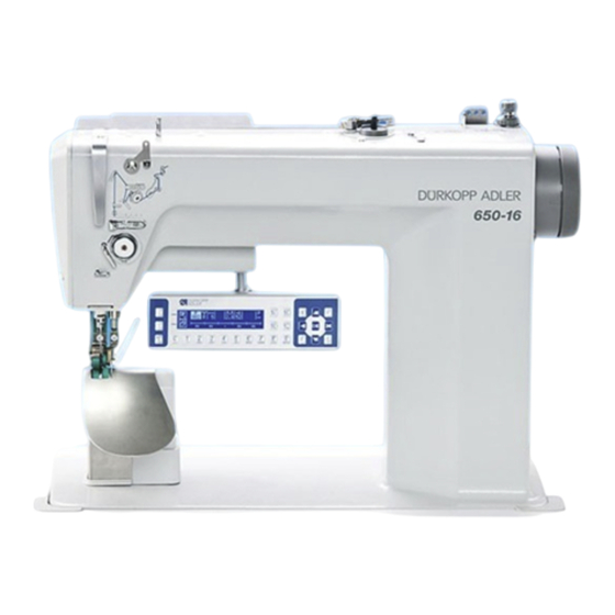
(1) - Plate (6) - Knee switch (2) - Drawe (7) - Control (3) - Frame (8) - Control panel (4) - Additional pedal (9) - Machine (5) - Pedal (10) - Thread reel holder Operating Instructions 650-16 - 02.0 - 08/2016... -
Page 18: Declaration Of Conformity
DIN EN 60204-31. Only authorized persons may work on the machine. Dürkopp Adler cannot be held liable for damages resulting from improper use. Operating Instructions 650-16 - 02.0 - 08/2016... - Page 19 Improper use can result in electric shock, crushing, cutting and punctures. Follow all instructions provided. NOTICE Property damage from non-observance! Improper use can result in material damage at the machine. Follow all instructions provided. Operating Instructions 650-16 - 02.0 - 08/2016...
- Page 20 Machine description Operating Instructions 650-16 - 02.0 - 08/2016...
-
Page 21: Operation
• Changing the needle • Threading the needle thread • Threading the looper thread • Adjusting the thread tension Switching on and off the machine Fig. 2: Switching on and off the machine Operating Instructions 650-16 - 02.0 - 08/2016... -
Page 22: Changing The Needle
Turn the main switch from position 0 to position I. The machine switches off. Changing the needle CAUTION Risk of injury from sharp parts! Punctures possible. Switch off the machine before changing the needle. Operating Instructions 650-16 - 02.0 - 08/2016... - Page 23 The groove (4) must face towards the hook tip (3). Tighten the screw (2). Order After changing to a different needle thickness, always adjust the clearance between the hook and the needle ( Service instructions). Operating Instructions 650-16 - 02.0 - 08/2016...
- Page 24 An incorrect hook distance can cause the following malfunctions: • Changing to a thinner needle: • Missing stitches • Thread damage • Changing to a thicker needle: • Damage to the hook tip • Damage to the needle Operating Instructions 650-16 - 02.0 - 08/2016...
-
Page 25: Threading The Needle Thread
Plug the thread reels on to the thread reel holders and feed the needle and hook threads through the unwinding bracket. Important The unwinding bracket must be horizontal and be positioned above the thread reels. Thread the needle thread as shown above. Operating Instructions 650-16 - 02.0 - 08/2016... - Page 26 Threads with high elasticity Fig. 5: Threading the needle thread: Threads with high elasticity To thread the needle thread when using threads with high elasti- city: Thread the needle thread as shwon above. Operating Instructions 650-16 - 02.0 - 08/2016...
-
Page 27: Winding The Hook Thread
Switch the main switch on. Start sewing. Once the bobbin is full, the winder switches off automatically ( Service instructions). Pull off the bobbin, clamp the thread under the cutter (3) and tear it off. Operating Instructions 650-16 - 02.0 - 08/2016... -
Page 28: Replacing The Hook Thread Bobbin
⑦ ③ ⑥ ④ ⑤ (1) - Bobbin housing flap (5) - Tension spring (2) - Hook cover (6) - Hole (3) - Bobbin (7) - Bobbin housing upper section (4) - Slot Operating Instructions 650-16 - 02.0 - 08/2016... -
Page 29: Thread Tension
The main tension (1) should be set as low as possible. The thread interlacing should be exactly in the middle of the material being sewn. With thin sewn material, excessive thread tension can lead to undesired gathering and thread breakages. Operating Instructions 650-16 - 02.0 - 08/2016... -
Page 30: Setting The Needle Thread Tension
To set the needle thread tension: Set the main tensioner (1) via the control panel so that a even stitch pattern is achieved. When the thread is cut, the main tensioner (1) is opened automatically. Operating Instructions 650-16 - 02.0 - 08/2016... -
Page 31: Setting The Hook Thread Tension
The basic setting for the tensioning spring is performed as follows: • When the bobbin housing contains a full bobbin it must sink slowly under its own weight. The braking spring prevents the bobbin running on when the thread has been cut. Operating Instructions 650-16 - 02.0 - 08/2016... - Page 32 Remove the hook thread in the direction of sewing at an angle of 45°. About half the tension value should be evident. Then tighten the adjusting screw (3) up to the recommended tension value. Operating Instructions 650-16 - 02.0 - 08/2016...
-
Page 33: Setting The Needle Thread Regulator
(1) - Screw (3) - Thread tensioning spring (2) - Needle thread regulator To set the needle thread regulator: Loosen the screw (1). Change the setting of the thread regulator (2). Tighten the screw (1). Operating Instructions 650-16 - 02.0 - 08/2016... -
Page 34: Raising The Presser Feet
The presser feet (1) can be raised by an electric motor, by depres- sing the pedal (3). To raise the presser feet: Push the pedal (3) halfway backwards. The presser feet (1) raise. Operating Instructions 650-16 - 02.0 - 08/2016... - Page 35 The value for fullness or curve support is selected. To activate the functions of the optional additional pedal: Push the additional pedal: • Push the pedal forwards: Increase the value • Push the pedal backwards: Decrease the value Operating Instructions 650-16 - 02.0 - 08/2016...
-
Page 36: Knee Switch
• Push the pedal half backwards. the seam The presser foot rises. • Position the sewing material. • Release the pedal. The presser foot descends on to the sewing material. At the start of the seam Operating Instructions 650-16 - 02.0 - 08/2016... - Page 37 The thread is cut off (if activated). The machine stops in the 2nd position. The needle is up. The presser feet are raised. • Remove the sewn material. • Release the pedal. The presser feet are lowered. Operating Instructions 650-16 - 02.0 - 08/2016...
- Page 38 Operation Operating Instructions 650-16 - 02.0 - 08/2016...
-
Page 39: Control With The Op3000 Control Panel
Control with the OP3000 control panel Control with the OP3000 control panel OP3000 control panel Fig. 15: OP3000 control panel All settings in the control for the 650-16 are performed using the OP3000 control panel. Function 0 to 16 Setting the fullness... -
Page 40: Switching On The Machine
• On the right of the screen the control software version The machine performs a reference run: The display shows the program last used, or manual mode. Fig. 17: Switching on the machine (2), Display of the program last used Operating Instructions 650-16 - 02.0 - 08/2016... -
Page 41: Control Operating Modes
Control with the OP3000 control panel Fig. 18: Switching on the machine (3), Display in manual mode Control operating modes The 650-16 control has 4 available operating modes: • Manual mode (program 000) Manual mode is the simplest operating mode. -
Page 42: Manual Mode
• Use the keys 0 to 16 to select the desired value. • Use the +/- key to select upper or lower fullness. • Use the second pedal to select the fullness, if fitted. Operating Instructions 650-16 - 02.0 - 08/2016... - Page 43 Measurement restarts when sewing starts again. Creating a program p. 58 Switch between upper and lower fullness ESC, F and S No function assigned 0 – 16 Fullness values No function assigned Operating Instructions 650-16 - 02.0 - 08/2016...
-
Page 44: Quick Access Function (Softkey Menu)
• Press the key 2. The bartacks are switched on or off. Needle position up / down • Press the key 3. If sewing is stopped within the seam, the needle is positioned up or down. Operating Instructions 650-16 - 02.0 - 08/2016... -
Page 45: Menu For Other Settings
Click on the OK button to confirm. Press or ESC to exit the menu. Symbol Meaning Alternate (foot alternation) Value range: 0.0 to 2.5 mm Foot Press. (presser foot pressure) Value range: 1 – 15 Operating Instructions 650-16 - 02.0 - 08/2016... -
Page 46: Sewing Process
Move the pedal to the 0 position. Change the desired parameter on the control panel. Push the pedal forwards again and sew. The seam will be sewn using the altered parameter value. Operating Instructions 650-16 - 02.0 - 08/2016... -
Page 47: Automatic Mode
The control switches to automatic mode and the following information appears in the display: Fig. 21: Automatic mode The following table shows the individual symbols in the display and the functions of the keys on the control panel. Operating Instructions 650-16 - 02.0 - 08/2016... -
Page 48: Before Starting Sewing
The thread tension can be altered before starting sewing. The altered value applies throughout the entire sewing program. to select the Thread tension parameter. • Use to change the thread tension Operating Instructions 650-16 - 02.0 - 08/2016... -
Page 49: Sewing
The program switches to the 1st step. 5.5.2 Sewing Push the pedal forwards and sew. The following information is shown on the display: Fig. 22: Sewing (1) ① ② (1) - Program bar (2) - Current step Operating Instructions 650-16 - 02.0 - 08/2016... - Page 50 Switch the sleeve side (if programmed) in the 1st step at the start of the step Correction of the thread tension The value is saved. ESC, P, F, S, No function assigned Operating Instructions 650-16 - 02.0 - 08/2016...
-
Page 51: Canceling The Program
Push the pedal fully back The program is interrupted. Quick programming is assigned to the upper softkey: Press the upper softkey The following display appears: Fig. 25: Quick programming (1) Continue with handling step 3. Operating Instructions 650-16 - 02.0 - 08/2016... - Page 52 or the keypad keys 0 – 9 to select a program num- ber. Press the OK key. The following information is shown on the display, the P in the program number field flashes: Fig. 27: Quick programming (3) Operating Instructions 650-16 - 02.0 - 08/2016...
- Page 53 • Use the +/- key to select upper (+) or lower (-) full- ness. Stitch length for the current step Value range: 1.0 to 5.5 mm • Use to select the Stitch length parameter. • Use to change the stitch length. Operating Instructions 650-16 - 02.0 - 08/2016...
-
Page 54: Creating A Program By Keyboard Input
Before the S key is pressed, program creation can be canceled at any time by pressing the ESC key. Once all steps are complete: Press the S key. The program is saved. Operating Instructions 650-16 - 02.0 - 08/2016... -
Page 55: Creating A Program By Sewing The Seam (Teach-In)
Before the S key is pressed, program creation can be canceled at any time by pressing the ESC key. If a section of seam has already been sewn the program will have been saved and must if necessary be deleted ( p. 61). Operating Instructions 650-16 - 02.0 - 08/2016... -
Page 56: Edit Mode
In Automatic mode, press the P key. The control switches to Edit mode. The program previously selected can now be edited. The following information is shown on the display, the P in the program number field flashes: Operating Instructions 650-16 - 02.0 - 08/2016... -
Page 57: Changing Further Parameters For The Current Step
The submenu opens. Use to select the desired parameter. Press the OK key to activate or deactivate the parameter, or use to change its value and press OK to confirm it. Operating Instructions 650-16 - 02.0 - 08/2016... -
Page 58: Changing Further Parameters For The Selected Program
Use to select the desired parameter. 4. Press the OK key to activate or deactivate the parameter, or use to change its value and press OK to confirm it. Operating Instructions 650-16 - 02.0 - 08/2016... - Page 59 Fulln. Corr. (fullness correction) Start Tack (bartack at the start of a seam) End Tack (bartack at the end of a seam) Thread Trim (thread cutoff) Exit the submenu using ESC or . Operating Instructions 650-16 - 02.0 - 08/2016...
-
Page 60: Programming Mode
Select another program number using or input a pro- gram number using the keypad keys 0 - 9 and then press The program number is loaded. The following display appears, with P flashing: Operating Instructions 650-16 - 02.0 - 08/2016... - Page 61 Select whether • the sleeve side that was programmed should be mirrored • the sleeve side that was programmed should not be mirro- • the teach-in for the 2nd sleeve side should be opened. Operating Instructions 650-16 - 02.0 - 08/2016...
-
Page 62: Copying The Program
Select another program number using or input a pro- gram number using the keypad keys 0 - 9 and then press The program number is loaded. The following display appears, with the program number flashing: Operating Instructions 650-16 - 02.0 - 08/2016... -
Page 63: Deleting A Program
To delete a program: Press the key. The softkey menu appears. Fig. 40: Deleting a program Press the key. Press the ESC key. The control exits Programming mode and reverts to Auto- matic mode. Operating Instructions 650-16 - 02.0 - 08/2016... -
Page 64: Mirroring The Program
To mirror a program: Press the key. The softkey menu appears. Fig. 41: Mirroring a program Press the key. Press the ESC key. The control exits Programming mode and reverts to Auto- matic mode. Operating Instructions 650-16 - 02.0 - 08/2016... -
Page 65: Control With The Op7000 Control Panel
The seam programs are displayed continuously whilst sewing is in progress. Programs can be mirrored for the other side of the sewing material. Operating Instructions 650-16 - 02.0 - 08/2016... -
Page 66: Switching On The Machine
(EDIT) and also optimized (Length Correction). • Service mode SERVICE Service mode contains functions for use during service work. Service mode is password-protected, to avoid accidentally changing the machine settings. Operating Instructions 650-16 - 02.0 - 08/2016... -
Page 67: General Operation
The user interface for inputting numeric values consists of the following elements: Header, consisting of: • Symbol of the selected parameter • Name of the parameter • Value range of the parameter • Symbol for exiting the user interface Operating Instructions 650-16 - 02.0 - 08/2016... - Page 68 Changing the value incrementally up or down Delete the input value Exit the user interface without inputting or saving any values Save the value that was input and exist the user interface Operating Instructions 650-16 - 02.0 - 08/2016...
-
Page 69: Entering Text
Fig. 44: Entering text The user interface for inputting text consists of the following ele- ments: Header, consisting of: • Symbol for a new seam program • Symbol for exiting the user interface Operating Instructions 650-16 - 02.0 - 08/2016... - Page 70 Exit the user interface without inputting or saving any text Input of a space Switching between upper case/lower case Delete letters/digits from the input line Save the value that was input and exist the user interface Operating Instructions 650-16 - 02.0 - 08/2016...
-
Page 71: Manual Mode Man
The symbols for all the parameters that can be set are displayed here. The gray fields above the parameter symbols show the respective current values. Right pane (4) Another user interface or another operating mode can be selected here. Operating Instructions 650-16 - 02.0 - 08/2016... -
Page 72: Parameters That Can Be Set In Man Mode
To set parameters in mode MAN: Press the desired button. The user interface for setting the parameter is displayed. For some parameters the setting is more than just a numerical value. These parameters are described below. Operating Instructions 650-16 - 02.0 - 08/2016... - Page 73 The type of fullness selected is displayed in an activated control field within the symbol. If a higher or lower degree of fullness is required, use the arrow keys to display more buttons. Input the fullness using the buttons 0 to 16. Operating Instructions 650-16 - 02.0 - 08/2016...
- Page 74 Input the curve support using the buttons 1 to 6. MAN mode Other program parameters After the Other program parameters button has been pressed, an overview of all the available parameters is displayed. Fig. 46: Other program parameters Operating Instructions 650-16 - 02.0 - 08/2016...
-
Page 75: Sewing Process
Move the pedal to the 0 position. Change the desired parameter on the control panel ( p. 70). Push the pedal forwards and sew. The seam will be sewn using the altered parameter value. Operating Instructions 650-16 - 02.0 - 08/2016... -
Page 76: Automatic Mode Auto
The number and the name of the selected seam program are displayed here, together with the symbols for all the parameters that can be set. The gray fields above the parameter symbols show the respective current values. Operating Instructions 650-16 - 02.0 - 08/2016... -
Page 77: Auto Parameters That Can Be Set
If the value is changed in AUTO Automatic mode it is permanently saved in the program. Setting the stitch length in mm. If the value is changed in AUTO Automatic mode it is permanently saved in the program. Operating Instructions 650-16 - 02.0 - 08/2016... - Page 78 AUTO. Press the Abort button to cancel the selection of the program. If necessary the seam program selected is discarded and the user interface for the Automatic mode AUTO is dis- played. Operating Instructions 650-16 - 02.0 - 08/2016...
- Page 79 • The sizes highlighted in red represent the reference sizes for the graduation logic. To set the sewing material size: Press on the desired sewing material size. The user interface for the Automatic mode AUTO is dis- played. Operating Instructions 650-16 - 02.0 - 08/2016...
- Page 80 • Upper (upper transport) • Lower (lower transport) The fullness selected is displayed in an activated control field. Display of further buttons for inputting the fullness. The buttons 0 to 16 are available for input. Operating Instructions 650-16 - 02.0 - 08/2016...
- Page 81 The fullness ratio can be set either by the buttons + F% and - F% or the fullness correction parameter. Fig. 51: Correcrting the fullness ratio To correct the fullness ratio: Input the correction value for the fullness in percent. Operating Instructions 650-16 - 02.0 - 08/2016...
- Page 82 After the Other program parameters button has been pressed, an overview of all the available parameters is displayed. Fig. 52: Other program parameters Parameters Meaning Foot Pressure Presser foot pressure Value range: 1 ... 10 Operating Instructions 650-16 - 02.0 - 08/2016...
-
Page 83: Sewing Process
Push the pedal forwards and sew the seam. The sewing progress is displayed graphically in the left pane as a red bar. Fig. 53: Sewing process The remaining sewing length per sewing step is displayed. Operating Instructions 650-16 - 02.0 - 08/2016... - Page 84 Push the pedal forwards and sew. The changed fullness value is applied and displayed. Cancel the seam program To cancel the seam program: Push the pedal fully back. The seam program is canceled. Operating Instructions 650-16 - 02.0 - 08/2016...
-
Page 85: Programming Mode
Right pane (4) Here new seam programs can be created ( p. 90), existing seam programs can be deleted ( p. 99), copied ( p. 99) and optimized ( p. 100) (Length Correction). Operating Instructions 650-16 - 02.0 - 08/2016... -
Page 86: Editing Existing Programs (Edit)
p. 88 Set the fullness in the current sewing step, p. 96 Set the curve support in the current sewing step Set the needle thread tension in the current sewing step Operating Instructions 650-16 - 02.0 - 08/2016... - Page 87 Press the desired button. The user interface for setting the desired parameter is dis- played. For some parameters the setting is more than just a numerical value. These extended parameters are described in detail below. Operating Instructions 650-16 - 02.0 - 08/2016...
- Page 88 • The sizes highlighted in red represent the reference sizes for the graduation logic. To set the sewing material size: Press on the desired sewing material size. The EDIT user interface of the programming mode is dis- played. Operating Instructions 650-16 - 02.0 - 08/2016...
- Page 89 • Upper (upper transport) • Lower (lower transport) The fullness selected is displayed in an activated control field. Display of further buttons for inputting the fullness. The buttons 0 to 16 are available for input. Operating Instructions 650-16 - 02.0 - 08/2016...
- Page 90 Input the fullness using the buttons 0 to 16. EDIT mode Other program parameters After the Other program parameters button has been pressed, an overview of all the available parameters is displayed. Fig. 57: Other program parameters Operating Instructions 650-16 - 02.0 - 08/2016...
- Page 91 Value range: 0, 1 EDIT mode Other sewing step parameters After the Other sewing step parameters button has been pressed, an overview of all the available parameters is displayed. Fig. 58: Other sewing step parameters Operating Instructions 650-16 - 02.0 - 08/2016...
-
Page 92: Creating A New Program (Programming)
• Operating mode EDIT is displayed. Press the P button. The PROGRAMMING user interface is displayed. Pressing the P button displays the number of the next free program slot. Fig. 59: Creating a new program (PROGRAMMING) (1) Operating Instructions 650-16 - 02.0 - 08/2016... - Page 93 The second sewing step is displayed with its number in the left pane. Fig. 60: Creating a new program (PROGRAMMING) (2) Repeat step 2 until all the sewing steps have been program- med. Operating Instructions 650-16 - 02.0 - 08/2016...
- Page 94 (mirror programmed side to other side), the other side of the sewing material should be programmed (program other side) or the programming should be ended (finish). Operating Instructions 650-16 - 02.0 - 08/2016...
- Page 95 There is only one display in the PRO- GRAMMING mode. A new program is automatically assigned the next free pro- gram slot. Select the right or left piece to be sewn Set the sewing material size, p. 95 Operating Instructions 650-16 - 02.0 - 08/2016...
- Page 96 Press the desired button. The user interface for setting the desired parameter is dis- played. For some parameters the setting is more than just a numerical value. These extended parameters are described in detail below. Operating Instructions 650-16 - 02.0 - 08/2016...
- Page 97 (>>). To set the sewing material size: Select the size system in the right pane. Press on the desired sewing material size. The PROGRAMMING user interface of the programming mode is displayed. Operating Instructions 650-16 - 02.0 - 08/2016...
- Page 98 • Upper (upper transport) • Lower (lower transport) The fullness selected is displayed in an activated control field. Display of further buttons for inputting the fullness. The buttons 0 to 16 are available for input. Operating Instructions 650-16 - 02.0 - 08/2016...
- Page 99 Input the fullness using the buttons 0 to 16. Mode Other program parameters PROGRAMMING After the Other program parameters button has been pressed, an overview of all the available parameters is displayed. Fig. 64: Other program parameters Operating Instructions 650-16 - 02.0 - 08/2016...
- Page 100 Value range: 0.0 ... 6.0 (% per size) Mode Other sewing step parameters PROGRAMMING After the Other sewing step parameters button has been pres- sed, an overview of all the available parameters is displayed. Fig. 65: Other sewing step parameters Operating Instructions 650-16 - 02.0 - 08/2016...
-
Page 101: Copying The Seam Program
A message is displayed asking whether you really wish to delete the active seam program. To delete the program, confirm by pressing the Yes button. The seam program is deleted. An appropriate message is displayed. Operating Instructions 650-16 - 02.0 - 08/2016... -
Page 102: Length Correction (Length Correction)
Fig. 66: Length correction (LENGHT CORRECTION) (1) Sew the sewing step. Switch to the next sewing step either manually at the control panel or using the knee switch. The sewing progress is displayed graphically. Operating Instructions 650-16 - 02.0 - 08/2016... -
Page 103: Service Mode Service
Service mode contains functions for use during service work. Service mode is password-protected, to avoid accidentally chan- ging the machine settings. More information on the contents of Service mode can be found in the Service instructions. Operating Instructions 650-16 - 02.0 - 08/2016... - Page 104 Control with the OP7000 control panel Operating Instructions 650-16 - 02.0 - 08/2016...
-
Page 105: Maintenance
Risk of injury from moving parts! During maintenance work, the machine may start up unintentionally and cause crushing. Switch off the main switch. Only perform maintenance work when the machine is switched off. Operating Instructions 650-16 - 02.0 - 08/2016... -
Page 106: Cleaning
The following areas must be cleaned with a compressed air pistol or a brush: • Throat plate (2) • Hook (1) • Bobbin case and interior • Thread trimmer • Needle • Engine fan filter (3) Operating Instructions 650-16 - 02.0 - 08/2016... - Page 107 Solvent-based cleaners may damage paintwork on the machine. Only use solvent-free substances for wiping the machine. Clean the machine as follows: Remove any lint and thread remnants using a compressed air pistol or a brush. Operating Instructions 650-16 - 02.0 - 08/2016...
-
Page 108: Lubricating
Oil is a pollutant and must not enter the sewage system or the soil. Carefully collect up used oil. Dispose of used oil and oily machine parts in accordance with the legal regulations. Operating Instructions 650-16 - 02.0 - 08/2016... - Page 109 Maintenance Fig. 69: Lubricating (1) - Joints on the gear (2) - Needle bar Operating Instructions 650-16 - 02.0 - 08/2016...
-
Page 110: Parts List
Maintenance Parts list A parts list can be ordered from Dürkopp Adler. Or visit our website for further information at: www.duerkopp-adler.com Operating Instructions 650-16 - 02.0 - 08/2016... -
Page 111: Setup
• Lashing straps and wooden blocks from the upper part of the machine, the table and the support frame • Restrain block and lashing straps from the sewing head Operating Instructions 650-16 - 02.0 - 08/2016... -
Page 112: Assembling The Frame
Attach the pedal (4) to the cross strut (5). Attach the additional pedal (3) (optional) to the cross strut (5). Attach the cross strut (5) to the frame. After the machine has been fully assembled, align the pedals, ( p. 113). Operating Instructions 650-16 - 02.0 - 08/2016... -
Page 113: Pre-Assembling The Table Top
Screw on the sewing light transformer (4). Screw on the main switch (5) (chipboard screws 5 x 30). Screw on the cable duct (6) (40 x 40 x 200 mm long) (chipboard screws 3.5 x 17). Operating Instructions 650-16 - 02.0 - 08/2016... -
Page 114: Completing The Table Top
Using 4.5 x 15 (4x) screws, screw on the hinge mountings (2). Using 4.5 x 55 (8x) screws, screw the edge strips (3) to the table top. Insert the upper part support (1). Operating Instructions 650-16 - 02.0 - 08/2016... -
Page 115: Attaching The Table Top And Pedals To The Frame
3. Turn the frame (3) the right way up. 4. Align the pedals (5) and (6). 5. For ergonomic reasons, align the pedals laterally so that the center of the main pedal (6) is directly beneath the needle. Operating Instructions 650-16 - 02.0 - 08/2016... - Page 116 Insert the thread reel holder (1) into the hole in the table top, and secure it with a nut and washer. 10. Fit and align the thread reel holders and unwinding bracket. Important The unwinding bracket must be vertically above the thread reel holders. Operating Instructions 650-16 - 02.0 - 08/2016...
-
Page 117: Setting The Working Height
Adjust the working height to the body dimension of the person who will operate the machine. The working height can be adjusted between 780 and 900 mm (measured to the upper edge of the table plate). Operating Instructions 650-16 - 02.0 - 08/2016... - Page 118 Slacken the screws (1) on the frame bars. Set the table top to the desired working height. To avoid jamming, slide the table top in or out evenly at both sides. Tighten the screws (1). Operating Instructions 650-16 - 02.0 - 08/2016...
-
Page 119: Inserting The Machine Upper Part
After the upper part has been placed in position, immediately connect the bracket (2) which prevents the upper part coming loose if the table top is tipped. Operating Instructions 650-16 - 02.0 - 08/2016... -
Page 120: Electrical Connection
ALWAYS pull the power plug before working on the electrical equipment. Important The voltage on the type plate of the sewing drive must correspond to the mains voltage. Operating Instructions 650-16 - 02.0 - 08/2016... -
Page 121: Connecting The Mains Power Supply
Replace the cover (3) on the main switch. 10. Fit the switch knob (1) and screw it tight. 11. Place the cable duct cover on the cable duct. Operating Instructions 650-16 - 02.0 - 08/2016... -
Page 122: Connecting The Cables To The Upper Part
Plug the motor cables to the corresponding plugs on the connection side (2). Plug the other cables to the corresponding plugs on the connection side (1). Connect the LED light to the transformer ( p. 131). Operating Instructions 650-16 - 02.0 - 08/2016... -
Page 123: Connecting The Cables For The Additional Control
(2), as shown in ( p. 120). Lay the cable (1) for the stepper motor in the underside of the casing (2) and plug it into the connection plug. Operating Instructions 650-16 - 02.0 - 08/2016... -
Page 124: Connecting The Setpoint Transducers To The Control
To connect the setpoint transducers to the control: Connect the setpoint transducer for the main pedal to the Speed plug (1) (X120b). Connect the setpoint transducer for the additional pedal to the Fullness plug (2) (X120t). Operating Instructions 650-16 - 02.0 - 08/2016... -
Page 125: Connecting The Equipotential Bonding For The Upper Part
To connect the equipotential bonding for the upper part: Screw the protective earth conductor (2) to the upper part (1). Lay it to the additional control cabinet and plug it on the flat plug (3). Operating Instructions 650-16 - 02.0 - 08/2016... -
Page 126: Connecting The Equipotential Bonding For The Control
Screw the protective earth conductor (3) of the plug (2) on to the control cabinet (1). Screw the protective earth conductor (4) (150 mm long) on to the frame (5) using a toothed shakeproof washer. Operating Instructions 650-16 - 02.0 - 08/2016... -
Page 127: Connecting The Equipotential Bonding For The Additional Control
To connect the equipotential bonding for the additional control: Plug the protective earth conductor (1) into the flat plug (2) on the additional control cabinet. Lay the cable (2) (300 mm long) to the control cabinet (3) and screw it on. Operating Instructions 650-16 - 02.0 - 08/2016... -
Page 128: Connecting The Equipotential Bonding For The Sewing Head Motor
(3) for sewing head drive. To cennect the equipotential bonding for the sewing head motor: Screw the protective earth conductor (2) to the earthing point on the control cabinet (1). Operating Instructions 650-16 - 02.0 - 08/2016... -
Page 129: Connecting The Equipotential Bonding For The Knee Switch
Screw the protective earth conductor (4) (650 mm long) to the attachment clip (1) on the knee switch. Lay the cable in the cable duct (2) and plug the additional control on to the flat plug (3). Operating Instructions 650-16 - 02.0 - 08/2016... -
Page 130: Connecting The Equipotential Bonding For The Setpoint Transducers
Lay the cable (4) through the cable duct (3) to the setpoint transducer (2) and screw it on (optional). Screw the protective earth conductor (1) (650 mm long) on to the setpoint transducer (2) and to the control cabinet (6). Operating Instructions 650-16 - 02.0 - 08/2016... -
Page 131: Connecting The Knee Switch
(3) - Knee switch (2) - Cable To connect the knee switch: Lay the cable (2) for the knee switch (3) through the cable duct to the control and connect it to the plug (1). Operating Instructions 650-16 - 02.0 - 08/2016... -
Page 132: Connecting The Control Panel
(X170 Panel). Connecting the control panel OP7000 Fig. 88: Connecting the control panel OP7000 ① ② ③ ④ (1) - Cable (3) - Retainer (2) - Table top opening (4) - Control panel Operating Instructions 650-16 - 02.0 - 08/2016... -
Page 133: Connecting The Led Sewing Light
Connect the plug (3) for the LED light to the black plug of the sewing light control output cable. 8.9.14 Connect the additional sewing light (Waldmann) (optional) See the installation manual 0791 100702. This manual is supplied with the sewing light. Operating Instructions 650-16 - 02.0 - 08/2016... -
Page 134: Sewing Test
12. If the requirements are not satisfied: Alter the thread tension ( p. 27) and ( p. 32). If necessary, also check the settings listed in the Service instruc- tions and correct them as required. Operating Instructions 650-16 - 02.0 - 08/2016... -
Page 135: Decommissioning
Remove residual oil from the oil pan using a cloth. Cover the control panel to protect it from contamination. Cover the control to protect it from soiling. Cover the entire machine if possible to protect it from conta- mination and damage. Operating Instructions 650-16 - 02.0 - 08/2016... - Page 136 Decommissioning Operating Instructions 650-16 - 02.0 - 08/2016...
-
Page 137: Disposal
When disposing of the machine, be aware that it consists of a range of different materials (steel, plastic, electronic components, etc.). Observe the applicable national regulations when disposing of these materials. Operating Instructions 650-16 - 02.0 - 08/2016... - Page 138 Disposal Operating Instructions 650-16 - 02.0 - 08/2016...
-
Page 139: Troubleshooting
Contact for repairs and issues with the machine: Dürkopp Adler AG Potsdamer Str. 190 33719 Bielefeld, Germany Tel. +49 (0) 180 5 383 756 Fax +49 (0) 521 925 2594 Email: service@duerkopp-adler.com Internet: www.duerkopp-adler.com Operating Instructions 650-16 - 02.0 - 08/2016... -
Page 140: Errors In Sewing Process
• Throat plate, hook or • Have parts reworked by spread have been dam- qualified specialists aged by the needle Operating Instructions 650-16 - 02.0 - 08/2016... - Page 141 • Check the parts based the desired sewing on the equipment sheet equipment • Throat plate, hook or • Have parts reworked by spread have been dam- qualified specialists aged by the needle Operating Instructions 650-16 - 02.0 - 08/2016...
- Page 142 • Needle thickness is • Use recommended nee- breakage unsuitable for the sew- ing material or the thread Seam • Residual tension is too • Adjust residual tension beginning tight for the needle not secure thread Operating Instructions 650-16 - 02.0 - 08/2016...
-
Page 143: Technical Data
70 - 120 Thread strength [Nm] max. 50/3 Stitch lenght [mm] 1,0 - 4,0 Max. speed 4000 [min Mains voltage 1x230 Mains frequency [Hz] Length [mm] Width [mm] 1320 Height [mm] 1300 Weight [kg] Operating Instructions 650-16 - 02.0 - 08/2016... - Page 144 Programs can be saved to a USB stick and transferred to other machines. The optional, ergonomically shaped table top provides additional assistance to working. Operating Instructions 650-16 - 02.0 - 08/2016...
-
Page 145: Appendix
Appendix 13 Appendix Dimensions for manufacturing a table top Operating Instructions 650-16 - 02.0 - 08/2016... - Page 146 Appendix Operating Instructions 650-16 - 02.0 - 08/2016...
- Page 147 Appendix Operating Instructions 650-16 - 02.0 - 08/2016...
- Page 148 Appendix Operating Instructions 650-16 - 02.0 - 08/2016...
- Page 150 DÜRKOPP ADLER AG Potsdamer Straße 190 33719 Bielefeld GERMANY Phone +49 (0) 521 / 925-00 service@duerkopp-adler.com E-mail www.duerkopp-adler.com...
Need help?
Do you have a question about the 650-16 and is the answer not in the manual?
Questions and answers