
Related Manuals for Pilz PNOZ m C0


Summary of Contents for Pilz PNOZ m C0
- Page 1 PNOZ m C0 Configurable, safe small controllers PNOZmulti 2 Operating Manual-1006013-EN-02...
- Page 2 We do assure you that all persons are regarded without discrim- ination and on an equal basis. All rights to this documentation are reserved by Pilz GmbH & Co. KG. Copies may be made for the user's internal purposes. Suggestions and comments for improving this documenta- tion will be gratefully received.
-
Page 3: Table Of Contents
Installation ..........................19 Control cabinet installation ......................19 6.1.1 Mounting distances ........................20 Dimensions in mm........................21 Commissioning ........................22 General wiring guidelines......................22 Connection ..........................22 Load project from chip card.......................24 Load project via USB port ......................24 Function test during commissioning..................24 Operating Manual PNOZ m C0 1006013-EN-02... - Page 4 12.2 Permitted ambient temperature Tamb dependent on the total current Isum ......35 Order reference ........................36 13.1 Product............................36 13.2 Accessories..........................36 13.2.1 Replacement terminals ......................36 13.2.2 Cable............................36 EC declaration of conformity ....................37 UKCA-Declaration of Conformity ..................38 Operating Manual PNOZ m C0 1006013-EN-02...
-
Page 5: Introduction
Introduction Introduction Validity of documentation This documentation is valid for the product PNOZ m C0 from Version HW:01, FW:01.01. This operating manual explains the function and operation, describes the installation and provides guidelines on how to connect the product. Using the documentation This document is intended for instruction. -
Page 6: Third-Party Manufacturer Licence Information
Third-party manufacturer licence information This product includes Open Source software with various licenses. Further information is available in the document "Third-party manufacturer licence informa- tion PNOZ m C0" (document number 1006087) at www.pilz.com. Operating Manual PNOZ m C0 1006013-EN-02... -
Page 7: Overview
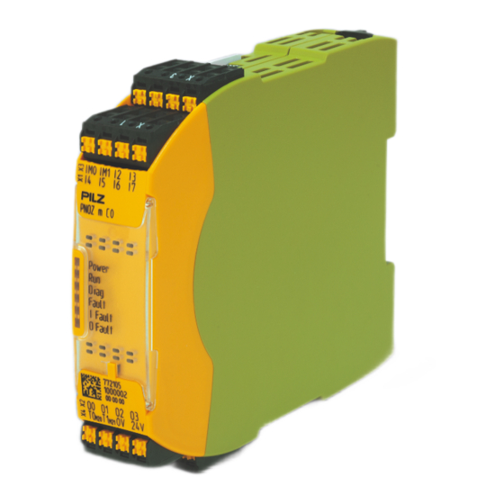
Overview Range Base unit PNOZ m C0 Unit features Application of the product PNOZ m C0: Standalone base unit of the configurable control system PNOZmulti 2 The product has the following features: Can be configured in the PNOZmulti Configurator Semiconductor outputs:... -
Page 8: Chip Card
Hardware version (HW) Legend Inputs I4 ... I7 Semiconductor outputs O0 ... O3 Configurable inputs/outputs IM0 and IM1 Inputs I2 ... I3 Configurable test pulse/auxiliary outputs T0M20 and T1M21 Supply connections 24 V and 0 V Operating Manual PNOZ m C0 1006013-EN-02... - Page 9 Overview LEDs: Power Diag Fault I Fault O Fault Operating Manual PNOZ m C0 1006013-EN-02...
-
Page 10: Safety
Safety Safety Intended use The standalone base unit PNOZ m C0 is used for the safety-related interruption of safety circuits and is designed for use in: Emergency stop equipment Safety circuits in accordance with VDE 0113 Part 1 and EN 60204-1 CAUTION! Inputs and outputs for standard functions must not be used for safety-re- lated applications. -
Page 11: Applicable Documentation
Have a good knowledge of the generic and specialist standards applicable to the specific application. 3.4.3 Warranty and liability All claims to warranty and liability will be rendered invalid if The product was used contrary to the purpose for which it is intended, Operating Manual PNOZ m C0 | 11 1006013-EN-02... -
Page 12: Disposal
Adequate protection must be provided for all inductive consumers. Do not open the housing or make any unauthorised modifications. Please make sure you shut down the supply voltage when performing maintenance work (e.g. exchanging contactors). Operating Manual PNOZ m C0 | 12 1006013-EN-02... -
Page 13: Security
– Ensure the authenticity of project data on the chip card The base unit PNOZ m C0 accepts project data on the chip card only if it has been generated using the identical security device key. - Page 14 – Make sure you regularly change the passwords of the user accounts on the system and/or ask the users to change their passwords themselves. – Make the users aware of the responsible use of their access data. Operating Manual PNOZ m C0 | 14 1006013-EN-02...
-
Page 15: Function Description
Please note that the reaction time is also increased by Delay times configured in the user program Delay on the sensor that is used Delay on the actuator that is used Example configuration: PNOZ m C0 Input Processing in the user Output... -
Page 16: Block Diagram
Device security 5.6.1 User management The base unit PNOZ m C0 can be protected from unauthorised access via user manage- ment. In order to access the device or perform specific actions via the PNOZmulti Configurator, a user must use his credentials to authenticate himself. -
Page 17: Security Device Key
Ensure authenticity of project data on the chip card The PNOZ m C0 accepts project data on the chip card only if it has been generated using the identical security device key. This happens automatically when project data is trans- ferred via the PNOZmulti Configurator or by selecting the correct security device key when the project data is saved directly to the chip card using the PNOZmulti Configurator. - Page 18 Function description NOTICE Please note To write a device key to a device, the device must be in stop state. Operating Manual PNOZ m C0 | 18 1006013-EN-02...
-
Page 19: Installation
NOTICE Damage due to electrostatic discharge! Electrostatic discharge can damage components. Ensure against discharge before touching the product, e.g. by touching an earthed, conductive sur- face or by wearing an earthed armband. Operating Manual PNOZ m C0 | 19 1006013-EN-02... -
Page 20: Mounting Distances
Please note that at the stated minimum distance, it will be difficult to swap the chip card from above. If you cannot leave a greater distance, remove the unit from the mounting rail to swap the chip card. Operating Manual PNOZ m C0 | 20 1006013-EN-02... -
Page 21: Dimensions In Mm
Installation Dimensions in mm 22,5 (0.88") Operating Manual PNOZ m C0 | 21 1006013-EN-02... -
Page 22: Commissioning
Emergency stop with detection of shorts across contacts T1M21 T0M20 T0M20 Start circuit Input circuit without detection Input circuit with detection of of shorts across contacts shorts across contacts T0M20 Operating Manual PNOZ m C0 | 22 1006013-EN-02... - Page 23 Please note that, in the event of an error in the feedback loop, the safety system switches to a safe state and shuts down all the outputs. Feedback loop Redundant output Contacts from external contactors O0 (O2) O1 (O3) Operating Manual PNOZ m C0 | 23 1006013-EN-02...
-
Page 24: Load Project From Chip Card
It is essential to check that the safety devices operate correctly – After the project has been loaded from the chip card – After the project has been loaded from the PNOZmulti Configurator via the USB port Operating Manual PNOZ m C0 | 24 1006013-EN-02... -
Page 25: Using The Chip Card
Make sure that you do not bend the chip card as you insert it into the chip card slot. The chip card is not required in order to operate the device. To remove the chip card, press on the chip card and then pull it out. Operating Manual PNOZ m C0 | 25 1006013-EN-02... -
Page 26: Connection Example
Commissioning Connection example Operating Manual PNOZ m C0 | 26 1006013-EN-02... -
Page 27: Operation
External error on the outputs of the base unit, which does not lead to a safe state, e.g. feedback input defective or short across contacts on a signal output Operating Manual PNOZ m C0 | 27 1006013-EN-02... -
Page 28: Factory Reset
When the o3 terminal LED lights, create a short across the contacts at o3 to 24 V and then remove it as soon as the o3 LED goes out. The base unit performs a factory reset, which is completed successfully when the Diag LED flashes rapidly. Operating Manual PNOZ m C0 | 28 1006013-EN-02... -
Page 29: Maintenance And Testing
Maintenance and testing Maintenance and testing It is not necessary to perform maintenance work on the product in normal operation. Please return any faulty products to Pilz. Operating Manual PNOZ m C0 | 29 1006013-EN-02... -
Page 30: Technical Details
Input voltage in accordance with EN 61131-2 Type 1 24 V DC Input current at rated voltage 5 mA Input current range 2,5 - 5,3 mA Pulse suppression 0,5 ms Maximum input delay 14 ms Operating Manual PNOZ m C0 | 30 1006013-EN-02... - Page 31 Temperature range -25 - 70 °C Climatic suitability In accordance with the standard EN 60068-2-30, EN 60068-2-78 Condensation during operation Not permitted Max. operating height above sea level 2000 m EN 61131-2 Operating Manual PNOZ m C0 | 31 1006013-EN-02...
- Page 32 0,2 - 2,5 mm², 24 - 12 AWG Spring-loaded terminals: Terminal points per connec- tion Stripping length with spring-loaded terminals 9 mm Dimensions Height 101,4 mm Width 22,5 mm Depth 120 mm Operating Manual PNOZ m C0 | 32 1006013-EN-02...
-
Page 33: Safety Characteristic Data
EN/IEC 61508-6 and EN/IEC 61511 and as the proof test interval and mission time in accordance with EN IEC 62061. All the units used within a safety function must be considered when calculating the safety characteristic data. Operating Manual PNOZ m C0 | 33 1006013-EN-02... -
Page 34: Classification According To Zvei, Cb24I
Max. capacitive load 65 nF Single-pole output Interfaces Source Interface Module Class Drain Interface Actuator Class C1, C2 Source parameters Max. test pulse duration 400 µs Max. rated current Max. capacitive load 1 µF Operating Manual PNOZ m C0 | 34 1006013-EN-02... -
Page 35: Supplementary Data
12.2 Permitted ambient temperature Tamb dependent on the total current Isum Isum Tamb [°C] A derating of 133 mA per 1°C must occur from an ambient temperature of 45 °C and above. Operating Manual PNOZ m C0 | 35 1006013-EN-02... -
Page 36: Order Reference
PSSu A USB-CAB03 PSSu, USB cable, length 3 m. 312992 Cable/XX/USB- Connection cable, USB 2.0 Type A on USB 2.0 Type Mini-B, con- 772300 ASMX/MIN-BAMX/U/ ductor cross section: 0.09 mm², shielded, cable length: 3 m 003/Q009/SH Operating Manual PNOZ m C0 | 36 1006013-EN-02... -
Page 37: Ec Declaration Of Conformity
European Parliament and of the Council. The complete EC Declaration of Conformity is available on the Internet at www.pilz.com/downloads. Authorised representative: Norbert Fröhlich, Pilz GmbH & Co. KG, Felix-Wankel-Str. 2, 73760 Ostfildern, Germany Operating Manual PNOZ m C0... -
Page 38: Ukca-Declaration Of Conformity
2008. The complete UKCA Declaration of Conformity is available on the Internet at www.pilz.com/ downloads. Representative: Pilz Automation Technology, Pilz House, Little Colliers Field, Corby, Northamptonshire, NN18 8TJ United Kingdom, eMail: mail@pilz.co.uk Operating Manual PNOZ m C0 | 38... - Page 39 We are represented internationally. Please refer to our homepage www.pilz.com for further details or contact our headquarters. Headquarters: Pilz GmbH & Co. KG, Felix-Wankel-Straße 2, 73760 Ostfildern, Germany Telephone: +49 711 3409-0, Telefax: +49 711 3409-133, E-Mail: info@pilz.com, Internet: www.pilz.com...
Need help?
Do you have a question about the PNOZ m C0 and is the answer not in the manual?
Questions and answers