
Related Manuals for Pilz PNOZ m3p (ETH)


Summary of Contents for Pilz PNOZ m3p (ETH)
- Page 1 PNOZ m3p (ETH) Configurable, safe small controllers PNOZmulti Classic Operating Manual-1001352-EN-09...
- Page 2 Preface This document is the original document. All rights to this documentation are reserved by Pilz GmbH & Co. KG. Copies may be made for the user's internal purposes. Suggestions and comments for improving this documenta- tion will be gratefully received.
-
Page 3: Table Of Contents
Contents Introduction ..........................Validity of documentation......................Using the documentation ......................Definition of symbols......................... Overview ..........................Range ............................Unit features ..........................Chip card ..........................Front view ..........................Safety ............................Intended use ..........................System requirements ........................ Safety regulations ........................3.3.1 Safety assessment ........................ - Page 4 Contents 6.4.2 Load project via integrated interface..................Download modified project to the PNOZmulti system .............. 6.5.1 Load modified project from chip card..................6.5.2 Load modified project via integrated interface ................Connection..........................Connection example ......................... Operation ..........................LED indicators .......................... 7.1.1 Display elements for the Ethernet connection (only PNOZ m3p ETH) ........
-
Page 5: Introduction
Introduction Introduction Validity of documentation This documentation is valid for the product PNOZ m3p. It is valid until new documentation is published. This operating manual explains the function and operation, describes the installation and provides guidelines on how to connect the product. Using the documentation This document is intended for instruction. - Page 6 Introduction INFORMATION This gives advice on applications and provides information on special fea- tures. Operating Manual PNOZ m3p (ETH) 1001352-EN-09...
-
Page 7: Overview
Overview Overview Range Base unit PNOZ m3p Terminator Documentation on data medium Unit features Application of the product PNOZ m3p: Base unit from the configurable control system PNOZmulti The product has the following features: Designed to monitor and control furnaces Can be configured in the PNOZmulti Configurator Positive-guided relay outputs: –... -
Page 8: Chip Card
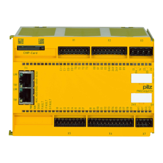
Overview – Supply voltage – Output circuits – Input circuits Test pulse outputs used to monitor shorts across the inputs Monitoring of shorts between the safety outputs Integrated interfaces: – PNOZ m3p: Serial interface RS232 – PNOZ m3p ETH: 2 Ethernet interfaces Plug-in connection terminals: Either spring-loaded terminal or screw terminal available as an accessory (see Order ref- erences for accessories). - Page 9 Overview PNOZ m3p ETH CHIP-Card Legend: CHIP card: – Interface chip card – Cascading inputs and outputs CI and CO, – Test pulse outputs T0 ... T3 – Semiconductor outputs O0 ... O3, – Auxiliary output OA0, – Supply connections –...
- Page 10 Overview LEDs: – PWR – RUN – DIAG – FAULT – I FAULT – O FAULT Operating Manual PNOZ m3p (ETH) | 10 1001352-EN-09...
-
Page 11: Safety
Safety Safety Intended use The configurable small control systems PNOZmulti are used for the safety-related interrup- tion of safety circuits and are designed for use in: E-STOP equipment Safety circuits in accordance with VDE 0113 Part 1 and EN 60204-1 The unit is designed to control and monitor furnaces in accordance with the standards: EN 12953-7: Shell boilers EN 12952-8: Water-tube boilers and auxiliary installations EN 61508: SIL 3: Functional safety of safety-related electrical/electronic/programmable... -
Page 12: System Requirements
Safety Slave burner with indirect ignition and joint flame monitoring Slave burner with indirect ignition and separate flame monitoring CAUTION! Inputs and outputs for standard functions must not be used for safety-re- lated applications. The following is deemed improper use in particular Any component, technical or electrical modification to the product, Use of the product outside the areas described in this manual, Use of the product outside the technical details (see... -
Page 13: Use Of Qualified Personnel
Safety 3.3.2 Use of qualified personnel The products may only be assembled, installed, programmed, commissioned, operated, maintained and decommissioned by competent persons. A competent person is a qualified and knowledgeable person who, because of their train- ing, experience and current professional activity, has the specialist knowledge required. To be able to inspect, assess and operate devices, systems and machines, the person has to be informed of the state of the art and the applicable national, European and international laws, directives and standards. -
Page 14: Function Description
Function description Function description Integrated protection mechanisms The relay meets the following safety requirements: The circuit is redundant with built-in self-monitoring. The safety device remains effective in the case of a component failure. The relay contacts meet the requirements for protective separation through increased in- sulation compared with all other circuits in the safety system. -
Page 15: Block Diagram
Function description The following oil and gas burner types can be monitored: Master burner with direct ignition Master burner with indirect ignition and joint flame monitoring Master burner with indirect ignition and separate flame monitoring Slave burner with direct ignition Slave burner with indirect ignition and joint flame monitoring Slave burner with indirect ignition and separate flame monitoring Block diagram... -
Page 16: Safety Mat, Muting
Function description Safety mat, muting INFORMATION Detailed information on these functions and connection examples can be found in the online help for the PNOZmulti Configurator and in the docu- ment entitled "PNOZmulti - Special Applications". Interfaces The product PNOZ m3p ETH has two Ethernet interfaces, the product PNOZ m3p has one serial interface to Project download Read the diagnostic data... -
Page 17: Installation
Installation Installation Control cabinet installation The control system should be installed in a control cabinet with a protection type of at least IP54. Fit the control system to a horizontal mounting rail. The venting slots must face upward and downward. Other mounting positions could destroy the control system. Use the locking elements on the rear of the unit to attach it to a mounting rail. -
Page 18: Dimensions
Installation Dimensions 135 (5.31") 94 (3.70") Install base unit without expansion module The terminator must be fitted to the side of the base unit marked “Termination/Link”. Do not fit a terminator on the left hand side of the base unit. Termination/Link Terminator Operating Manual PNOZ m3p (ETH) -
Page 19: Connecting The Base Unit And Expansion Modules
Installation Connecting the base unit and expansion modules The position of the expansion modules is defined in the PNOZmulti Configurator. The ex- pansion modules are connected to the left or right of the base unit, depending on the type. Please refer to the document "PNOZmulti System Expansion" for details of the number of modules that can be connected to the base unit and the module types. -
Page 20: Commissioning
Commissioning Commissioning General wiring guidelines The wiring is defined in the circuit diagram in the Configurator. There you can select the in- puts that are to perform a safety function and the outputs that are to switch this safety func- tion. -
Page 21: Ethernet Interfaces (Eth Version Only)
Commissioning Ethernet interfaces (ETH version only) 6.2.1 RJ45 interfaces ("Ethernet") Two free switch ports are provided as Ethernet interfaces via an internal autosensing switch. The autosensing switch automatically detects whether data transfer is occurring at 10 Mbit/s or 100 Mbit/s. INFORMATION The connected subscribers must support the autosensing/autonegotiation function. -
Page 22: Rj45 Connection Cable
Commissioning 6.2.4 RJ45 connection cable RJ45 connector 8-pin 10BaseT cable or 100BaseTX cable max. 100 m NOTICE With the plug-in connection please note that the data cable and connector have a limited mechanical load capacity. Appropriate design measures should be used to ensure that the plug-in connection is insensitive to in- creased mechanical stress (e.g. -
Page 23: Process Data Exchange
Commissioning 6.2.5 Process data exchange The RJ45 interfaces on the internal autosensing switch enable process data to be ex- changed with other Ethernet subscribers within a network. The product PNOZ m3p can also be connected to Ethernet via a hub (hub or switch). Ethernet Hub/Switch Hub/Switch... -
Page 24: Commissioning The Pnozmulti Control System For The First Time
Commissioning Commissioning the PNOZmulti control system for the first time Procedure: Wire the inputs and outputs on the base unit and expansion modules in accordance with the circuit diagram. Cascading output as auxiliary output: Connect the load to CO+ and A2, see connection example. -
Page 25: Download Modified Project To The Pnozmulti System
Commissioning Download modified project to the PNOZmulti system 6.5.1 Load modified project from chip card To download data via chip card, the existing configuration data must first be deleted (gen- eral reset of device). Procedure: Switch off the supply voltage. Disconnect all the output terminals. - Page 26 Commissioning Input circuit Single-channel Dual-channel E-STOP without detection of shorts across contacts E-STOP with detection of shorts across contacts Connection examples for the input circuit Start circuit Input circuit without detection of Input circuit with detection of shorts across contacts shorts across contacts Connection examples for start circuit Redundant output...
- Page 27 Commissioning Redundant output Single output Connection examples for relay outputs Feedback loop Redundant output Contacts from external contactors O0 (O2, O4) O1 (O3, O5) Connection examples for feedback loop Operating Manual PNOZ m3p (ETH) | 27 1001352-EN-09...
-
Page 28: Connection Example
Commissioning Connection example Dual-channel E-STOP and safety gate wiring, monitored start (I17), feedback loop (I14), cascading output as auxiliary output (CO+/A2) Operating Manual PNOZ m3p (ETH) | 28 1001352-EN-09... -
Page 29: Operation
Operation Operation When the supply voltage is switched on, the PNOZmulti copies the configuration from the chip card. The PNOZmulti control system is ready for operation when the "POWER" and "RUN" LEDs on the base unit are lit continuously. LED indicators Legend LED on LED flashes... -
Page 30: Display Elements For The Ethernet Connection (Only Pnoz M3P Eth)
Operation Basis Exp. Error External error on the inputs, which does not lead to a safe condition, e.g. partially operated; feed- back input defective The fieldbus module has not been recognised. The base unit has been identified via the PNOZmulti Configurator. Error on cascading input;... -
Page 31: Reset Ethernet Connection Settings
Operation Reset Ethernet connection settings The Ethernet connection settings of the base unit can be configured in the PNOZmulti Con- figurator. You can reset the base unit's Ethernet connection settings to the default settings. Proceed as follows: Switch off the supply voltage Remove the chip card Restart the base unit without the chip card inserted. -
Page 32: Technical Details
Technical Details Technical Details General 773125 773126 BG, CCC, CE, EAC (Eurasian), BG, CCC, CE, EAC (Eurasian), Certifications KCC, KOSHA, cULus Listed KCC, cULus Listed Electrical data 773125 773126 Supply voltage Supply to the system Supply to the system Voltage 24 V 24 V Kind... - Page 33 Technical Details Semiconductor outputs 773125 773126 Switching capability Voltage 24 V 24 V Current Power 48 W 48 W Signal level at "1" UB - 0.5 VDC at 2 A UB - 0.5 VDC at 2 A Residual current at "0" 0,5 mA 0,5 mA Max.
- Page 34 Technical Details Relay outputs 773125 773126 Utilisation category of safety con- tacts AC15 at 230 V 230 V Max. current Max. power 690 W 690 W DC13 (6 cycles/min) at 24 V 24 V Max. current Max. power 72 W 72 W Airgap creepage between Relay contacts...
- Page 35 Technical Details Environmental data 773125 773126 Ambient temperature In accordance with the standard EN 60068-2-14 EN 60068-2-14 Temperature range 0 - 60 °C 0 - 60 °C Forced convection in control cabinet off 55 °C 55 °C Storage temperature In accordance with the standard EN 60068-2-1/-2 EN 60068-2-1/-2 Temperature range -25 - 70 °C...
- Page 36 Technical Details Mechanical data 773125 773126 DIN rail Top hat rail 35 x 7,5 EN 50022 35 x 7,5 EN 50022 Recess width 27 mm 27 mm Max. cable length Max. cable length per input 1 km 1 km Sum of individual cable lengths at the test pulse output 40 km 40 km...
-
Page 37: Safety Characteristic Data
Technical Details Mechanical data 773125 773126 Stripping length with spring-loaded terminals 9 mm 9 mm Stripping length with spring-loaded terminals (relay outputs) 10 mm 10 mm Dimensions Height 94 mm 94 mm Width 135 mm 135 mm Depth 121 mm 121 mm Weight 499 g... - Page 38 Technical Details All the units used within a safety function must be considered when calculating the safety characteristic data. INFORMATION A safety function's SIL/PL values are not identical to the SIL/PL values of the units that are used and may be different. We recommend that you use the PAScal software tool to calculate the safety function's SIL/PL values.
-
Page 39: Supplementary Data
Supplementary data Supplementary data Service life graph for the relay contacts The service life graphs indicate the number of cycles from which failures due to wear must be expected. The wear is mainly caused by the electrical load; the mechanical load is negli- gible. - Page 40 Supplementary data Example Inductive load: 0.2 A Utilisation category: AC15 Contact service life: 1 000 000 cycles Provided the application to be implemented requires fewer than 1 000 000 cycles, the PFH value (see Technical details [ 32]) can be used in the calculation. To increase the service life, sufficient spark suppression must be provided on all relay con- tacts.
-
Page 41: Order Reference
Order reference Order reference 10.1 Product Product type Features Order No. PNOZ m3p Base unit 773 125 PNOZ m3p ETH Base unit, Ethernet interface 773 126 10.2 Accessories Connection terminals Product type Features Order No. Set spring terminals 1 set of spring-loaded terminals 783 100 Set screw terminals 1 set of screw terminals... - Page 42 We are represented internationally. Please refer to our homepage www.pilz.com for further details or contact our headquarters. Headquarters: Pilz GmbH & Co. KG, Felix-Wankel-Straße 2, 73760 Ostfildern, Germany Telephone: +49 711 3409-0, Telefax: +49 711 3409-133, E-Mail: info@pilz.com, Internet: www.pilz.com...
Need help?
Do you have a question about the PNOZ m3p (ETH) and is the answer not in the manual?
Questions and answers