
Related Manuals for Pilz PNOZ m EF SafetyNET


Summary of Contents for Pilz PNOZ m EF SafetyNET
- Page 1 PNOZ m EF SafetyNET Configurable, safe small controllers PNOZmulti 2 Operating Manual-1004535-EN-03...
- Page 2 Preface This document is the original document. All rights to this documentation are reserved by Pilz GmbH & Co. KG. Copies may be made for the user's internal purposes. Suggestions and comments for improving this documenta- tion will be gratefully received.
-
Page 3: Table Of Contents
Download modified project to the PNOZmulti system .............. Operation ..........................LED indicators .......................... Diagnostics and behaviour in case of an error ................. Technical details ........................Safety characteristic data ......................Order reference ........................Product ............................. Operating Manual PNOZ m EF SafetyNET 1004535-EN-03... - Page 4 Contents Accessories ..........................Operating Manual PNOZ m EF SafetyNET 1004535-EN-03...
-
Page 5: Introduction
Introduction Introduction Validity of documentation This documentation is valid for the product PNOZ m EF SafetyNET from Version HW:02, FW:01.01. This operating manual explains the function and operation, describes the installation and provides guidelines on how to connect the product. - Page 6 Introduction INFORMATION This gives advice on applications and provides information on special fea- tures. Operating Manual PNOZ m EF SafetyNET 1004535-EN-03...
-
Page 7: Overview
PNOZ m EF SafetyNET. Up to 16 SafetyNET p subscribers can be connected in a line structure. The module PNOZ m EF SafetyNET is connected as the first safe module to the left of the base unit. LED display for communication via SafetyNET p and for displaying errors. -
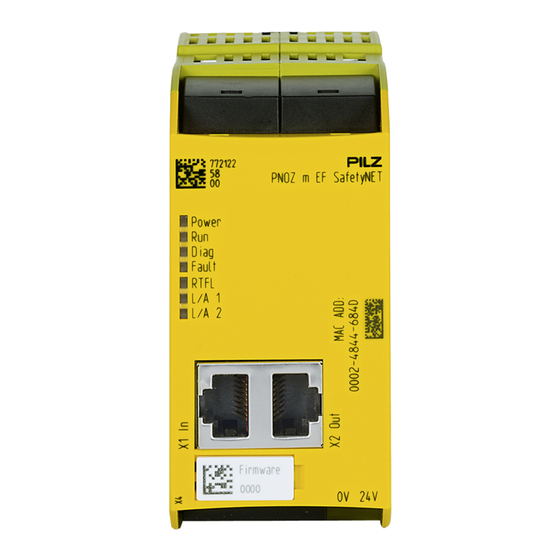
Page 8: Front View
To determine the version of the device, please note: The firmware version number is on the labelling clip. This is also the version number that must be selected in the PNOZmulti Configurator under Version during the hardware config- uration. Operating Manual PNOZ m EF SafetyNET 1004535-EN-03... -
Page 9: Safety
E-STOP equipment Safety circuits in accordance with VDE 0113 Part 1 and EN 60204-1 The product PNOZ m EF SafetyNET meets the requirements of the standards EN 81-20, EN 81-22 and EN 81-50, harmonised under the Lifts Directive 2014/33/EU, and the re- quirements of the standard EN 115-1, harmonised under the Machinery Directive 2006/42/EC. -
Page 10: Safety Regulations
In safety-related applications, please comply with the mission time T in the safety-related characteristic data. When decommissioning, please comply with local regulations regarding the disposal of electronic devices (e.g. Electrical and Electronic Equipment Act). Operating Manual PNOZ m EF SafetyNET | 10 1004535-EN-03... -
Page 11: For Your Safety
Do not open the housing or make any unauthorised modifications. Please make sure you shut down the supply voltage when performing maintenance work (e.g. exchanging contactors). Operating Manual PNOZ m EF SafetyNET | 11 1004535-EN-03... -
Page 12: Function Description
The safety device remains effective in the case of a component failure. Functions The expansion module PNOZ m EF SafetyNET is used for safe data exchange between several SafetyNET p subscribers via SafetyNET p RTFL. The safe virtual inputs and outputs that are defined via SafetyNET p are selected and con- figured for each PNOZmulti 2 system in PNOZmulti Configurator. -
Page 13: System Reaction Time
Calculation of the maximum reaction time between an input switching off and a linked out- put in the system switching off is described in the document "PNOZmulti System Expan- sion". Block diagram 24 V Module SafetyNET p Supply Data (FS) Operating Manual PNOZ m EF SafetyNET | 13 1004535-EN-03... -
Page 14: Installation
(see diagram). The values stated for the mounting distances are minimum specifications. The ambient temperature in the control cabinet must not exceed the figure stated in the technical details. Air conditioning may otherwise be required. Operating Manual PNOZ m EF SafetyNET | 14 1004535-EN-03... -
Page 15: Dimensions In Mm
Connect the base unit and the expansion module as described in the operating instructions for the base units. Connect the black/yellow terminator to the expansion module. Install the expansion module in the position in which it is configured in the PNOZmulti Configurator. Operating Manual PNOZ m EF SafetyNET | 15 1004535-EN-03... - Page 16 Please refer to the document "PNOZmulti System Expansion" for details of the number of modules that can be connected to the base unit and the module types. Operating Manual PNOZ m EF SafetyNET | 16 1004535-EN-03...
-
Page 17: Commissioning
Connect the supply voltage to the fieldbus module: 24 V terminal: + 24 VDC 0 V terminal: 0 V Protect the supply voltage as follows: – Circuit breaker, characteristic C - 6 A – Blow-out fuse, slow, 6A Operating Manual PNOZ m EF SafetyNET | 17 1004535-EN-03... -
Page 18: Interface Assignment
The SafetyNET p subscribers can be connected in the SafetyNET p line in any sequence when all the PNOZmulti SafetyNET p subscribers have the same version. This has no in- fluence on communication. Operating Manual PNOZ m EF SafetyNET | 18 1004535-EN-03... - Page 19 FW:01.01 FW:01.00 Fig.: SafetyNET p line with different versions of PNOZ m EF SafetyNET. Up to 16 SafetyNET p subscribers can be connected in a line structure. The SafetyNET p subscribers must be connected directly. No Ethernet switch must be in- terposed.
-
Page 20: Download Modified Project To The Pnozmulti System
Changes to the SafetyNET p connection have to be adapted in the software tool PNOZmulti Network Editor. NOTICE For the commissioning and after every program change, you must check whether the safety devices are functioning correctly. Operating Manual PNOZ m EF SafetyNET | 20 1004535-EN-03... -
Page 21: Operation
No data connection via SafetyNET p RTFL. The module is reached by the bus master when establishing the SafetyNET p RTFL connection. All subscribers are synchronised when establishing the SafetyNET p RTFL connection. Operating Manual PNOZ m EF SafetyNET | 21 1004535-EN-03... -
Page 22: Diagnostics And Behaviour In Case Of An Error
Whether the number of configured SafetyNET p modules matches the number of connec- ted SafetyNET p modules. Whether the device address of the configured SafetyNET p modules matches the device address of the connected SafetyNET p modules. Operating Manual PNOZ m EF SafetyNET | 22 1004535-EN-03... -
Page 23: Technical Details
In accordance with the standard EN 60068-2-30, EN 60068-2-78 Humidity 93 % r. h. at 40 °C Condensation during operation Not permitted Max. operating height above sea level 2000 m EN 61131-2 Operating Manual PNOZ m EF SafetyNET | 23 1004535-EN-03... - Page 24 Conductor cross section with spring-loaded terminals: Flexible with/without crimp connector 0,2 - 2,5 mm², 24 - 12 AWG Spring-loaded terminals: Terminal points per connec- tion Stripping length with spring-loaded terminals 9 mm Operating Manual PNOZ m EF SafetyNET | 24 1004535-EN-03...
-
Page 25: Safety Characteristic Data
A safety function's SIL/PL values are not identical to the SIL/PL values of the units that are used and may be different. We recommend that you use the PAScal software tool to calculate the safety function's SIL/PL values. Operating Manual PNOZ m EF SafetyNET | 25 1004535-EN-03... -
Page 26: Order Reference
Connection terminals and jumper Product type Features Order no. Spring terminals Screw terminals, 1 piece 750 017 Spring terminals Spring-loaded terminals, 1 piece 751 017 Jumper PNOZ mm0.xp connector left (10 pcs) 779 260 Operating Manual PNOZ m EF SafetyNET | 26 1004535-EN-03... - Page 27 We are represented internationally. Please refer to our homepage www.pilz.com for further details or contact our headquarters. Headquarters: Pilz GmbH & Co. KG, Felix-Wankel-Straße 2, 73760 Ostfildern, Germany Telephone: +49 711 3409-0, Telefax: +49 711 3409-133, E-Mail: info@pilz.com, Internet: www.pilz.com...
Need help?
Do you have a question about the PNOZ m EF SafetyNET and is the answer not in the manual?
Questions and answers