
Related Manuals for Pilz PNOZ mml1p


Summary of Contents for Pilz PNOZ mml1p
- Page 1 PNOZ mml1p Configurable, safe compact controllers PNOZmulti Mini Operating Manual-1002233-EN-06...
- Page 2 Preface This document is the original document. All rights to this documentation are reserved by Pilz GmbH & Co. KG. Copies may be made for the user's internal purposes. Suggestions and comments for improving this documenta- tion will be gratefully received.
-
Page 3: Table Of Contents
......................6.4.1 Example: Series connection of 3 base units................6.4.2 Example: Connection of 5 base units ..................Operation ..........................LED indicators .......................... Fault detection .......................... Technical details ........................Order reference ........................Product ............................. Accessories ..........................Operating Manual PNOZ mml1p 1002233-EN-06... -
Page 4: Introduction
Introduction Introduction Validity of documentation This documentation is valid for the product PNOZ mml1p. It is valid until new documenta- tion is published. This operating manual explains the function and operation, describes the installation and provides guidelines on how to connect the product. - Page 5 Introduction INFORMATION This gives advice on applications and provides information on special fea- tures. Operating Manual PNOZ mml1p 1002233-EN-06...
-
Page 6: Overview
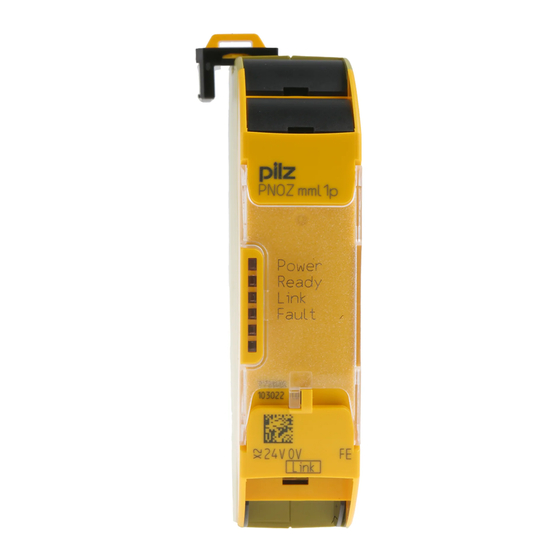
Scope of supply Expansion module PNOZ mml1p Jumper Unit features Application of the product PNOZ mml1p: Link module to safely connect two configurable small control systems PNOZmulti. The product has the following features: Connection options: – Two PNOZmulti Mini base units –... - Page 7 Overview Key: – 0 V, 24 V:Supply connections – FE: Functional earth Link: Connection LEDs: – Power – Ready – Link – Fault Operating Manual PNOZ mml1p 1002233-EN-06...
-
Page 8: Safety
In order to achieve the re- quired safety level for the overall plant/machine, define the safety requirements for the plant/machine and then define how these must be implemented from a technical and organ- isational standpoint. Operating Manual PNOZ mml1p 1002233-EN-06... -
Page 9: Use Of Qualified Personnel
PNOZmulti Configurator's online help. Only use these functions once you have read and understood the documentations. Do not open the housing or make any unauthorised modifications. Please make sure you shut down the supply voltage when performing maintenance work (e.g. exchanging contactors). Operating Manual PNOZ mml1p 1002233-EN-06... -
Page 10: Function Description
The safety device remains effective in the case of a component failure. Functions The link module PNOZ mml1p is used to safely transfer the input information from 32 virtual inputs and 32 virtual outputs between two PNOZmulti systems. One link module is as- signed to each base unit. - Page 11 The risk assessment must consider all hazards as regards the reaction time and the safety distance. The overall reaction time must not delay the arrival of a safe condition by more than the permitted time. Operating Manual PNOZ mml1p | 11 1002233-EN-06...
-
Page 12: Block Diagram
PNOZmulti system to input i5 on the other PNOZmulti system. Base unit 2 Base unit 1 Virtual inputs Virtual outputs Virtual outputs Virtual inputs Block diagram 24V 0V n.c.FE CA- CB+ CB- CGround Power Operating Manual PNOZ mml1p | 12 1002233-EN-06... -
Page 13: Installation
Damage due to electrostatic discharge! Electrostatic discharge can damage components. Ensure against discharge before touching the product, e.g. by touching an earthed, conductive sur- face or by wearing an earthed armband. Dimensions 100 (3,94") 22,5 (0.88") Operating Manual PNOZ mml1p | 13 1002233-EN-06... -
Page 14: Connect The Base Unit And Expansion Modules
Please refer to the document "PNOZmulti System Expansion" for details of the number of modules that can be connected to the base unit and the module types. Operating Manual PNOZ mml1p | 14 1002233-EN-06... -
Page 15: Commissioning
The max. cable length between two link modules on a connection with one link module – PNOZ ml1p <V2.0: 100 m – PNOZ ml1p from V2.0, PNOZ mml1p: 1000 m Connect the inputs and outputs from two link modules with 4-core shielded cable. The cables must be twisted in pairs. -
Page 16: Connection
Commissioning Connection RJ45 socket Layout 8-pin n.c. n.c. n.c. n.c. Shield CGround Supply voltage Supply voltage PNOZ mml1p PNOZ mml1p CGround CGround Connection of two base units PNOZmulti Mini via PNOZ mml1p Operating Manual PNOZ mml1p | 16 1002233-EN-06... -
Page 17: Connection Examples
O1 COND + (n * t ) + t COND = 4 ms + (2 * 35 ms ) + 30 ms = 104 ms I3 I6 Base 1 Base 2 Base 3 Operating Manual PNOZ mml1p | 17 1002233-EN-06... -
Page 18: Example: Connection Of 5 Base Units
O0 on Base 2: 69 ms O1 on Base 3: 104 ms O0 on Base 4: 139 ms O0 on Base 5: 104 ms I4 I6 I3 I6 Base 3 Base 1 Base 2 Base 4 Base 5 Operating Manual PNOZ mml1p | 18 1002233-EN-06... -
Page 19: Operation
When the supply voltage is switched on, the PNOZmulti copies the configuration from the chip card. The PNOZmulti safety system is ready for operation when the "POWER" and "RUN" LEDs on the base unit and the "READY" LED on the PNOZ mml1p are lit continuously. LED indicators Legend... -
Page 20: Technical Details
EN 60068-2-6 In accordance with the standard Frequency 10,0 - 150,0 Hz Acceleration Shock stress In accordance with the standard EN 60068-2-27 Acceleration Duration 11 ms Max. operating height above sea level 2000 m Operating Manual PNOZ mml1p | 20 1002233-EN-06... - Page 21 Spring-loaded terminals: Terminal points per connec- tion Stripping length with spring-loaded terminals 9 mm Dimensions Height 100,0 mm Width 22,5 mm Depth 120,0 mm 95 g Weight Where standards are undated, the 2011-01 latest editions shall apply. Operating Manual PNOZ mml1p | 21 1002233-EN-06...
-
Page 22: Order Reference
1 pc. Screw terminals PNOZ Screw terminals, 10 piece 793 539 mmc2p,mml1p 10 pcs. Terminator, jumper Product type Features Order no. PNOZ mm0.xp connector Jumper yellow/black to connect the modules, 10 pieces 779 260 left Operating Manual PNOZ mml1p | 22 1002233-EN-06... - Page 23 We are represented internationally. Please refer to our homepage www.pilz.com for further details or contact our headquarters. Headquarters: Pilz GmbH & Co. KG, Felix-Wankel-Straße 2, 73760 Ostfildern, Germany Telephone: +49 711 3409-0, Telefax: +49 711 3409-133, E-Mail: info@pilz.com, Internet: www.pilz.com...
Need help?
Do you have a question about the PNOZ mml1p and is the answer not in the manual?
Questions and answers