
Subscribe to Our Youtube Channel
Related Manuals for Pilz PNOZmulti Classic PNOZ ms3p TTL


Summary of Contents for Pilz PNOZmulti Classic PNOZ ms3p TTL
- Page 1 PNOZ ms3p TTL Configurable, safe small controllers PNOZmulti Classic Operating Manual-1001723-EN-05...
- Page 2 Preface This document is the original document. All rights to this documentation are reserved by Pilz GmbH & Co. KG. Copies may be made for the user's internal purposes. Suggestions and comments for improving this documenta- tion will be gratefully received.
-
Page 3: Table Of Contents
Contents Introduction ..........................Validity of documentation......................Using the documentation ......................Definition of symbols......................... Overview ..........................Scope............................Unit features ..........................Front view ..........................Safety ............................Intended use ..........................System requirements ........................ Safety regulations ........................3.3.1 Safety assessment ........................3.3.2 Use of qualified personnel ...................... - Page 4 Contents Accessories ..........................Application examples ......................10.1 Examples without position control .................... 10.1.1 Example 1 ..........................10.1.2 Example 2 ..........................10.2 Example with position control ....................Operating Manual PNOZ ms3p TTL 1001723-EN-05...
-
Page 5: Introduction
Introduction Introduction Validity of documentation This documentation is valid for the product PNOZ ms3p TTL. It is valid until new document- ation is published. This operating manual explains the function and operation, describes the installation and provides guidelines on how to connect the product. Using the documentation This document is intended for instruction. - Page 6 Introduction INFORMATION This gives advice on applications and provides information on special fea- tures. Operating Manual PNOZ ms3p TTL 1001723-EN-05...
-
Page 7: Overview
Overview Overview Scope Expansion module PNOZ ms3p TTL Jumper Unit features Application of the product PNOZ ms3p TTL: Speed monitor for connection to a base unit from the configurable control system PNOZmulti The product has the following features: Monitoring of 2 independent axes Connection per axis –... -
Page 8: Front View
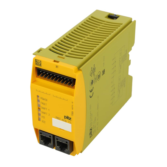
Overview Front view Key: X12: – Female connector for connecting an incremental encoder to axis 1 X22: – Female connector for connecting an incremental encoder to axis 2 LEDs: – POWER – FAULT – SHAFT 1 – SHAFT 2 – X12 –... -
Page 9: Safety
Safety Safety Intended use The expansion module monitors standstill, speed and direction of rotation in accordance with EN ISO 13849-1 up to PL e and EN IEC 62061 up to SIL CL 3. The expansion module may only be connected to a base unit from the PNOZmulti system (please refer to the document "PNOZmulti System Expansion"... -
Page 10: System Requirements
Safety The following is deemed improper use in particular Any component, technical or electrical modification to the product, Use of the product outside the areas described in this manual, Use of the product outside the technical details (see Technical details). NOTICE EMC-compliant electrical installation The product is designed for use in an industrial environment. -
Page 11: Warranty And Liability
Safety 3.3.3 Warranty and liability All claims to warranty and liability will be rendered invalid if The product was used contrary to the purpose for which it is intended, Damage can be attributed to not having followed the guidelines in the manual, Operating personnel are not suitably qualified, Any type of modification has been made (e.g. -
Page 12: Function Description
Function description Function description Integrated protection mechanisms The relay meets the following safety requirements: The circuit is redundant with built-in self-monitoring. The safety device remains effective in the case of a component failure. Operation The speed monitor can independently monitor two axes for standstill, speed and direction of rotation. -
Page 13: Incremental Encoders
The adapter records the data between the encoder and drive and makes it available to the PNOZ ms3p TTL via the RJ45 socket. Pilz supplies complete adapters as well as ready-made cable with RJ45 connector, which can be used when making your own adapter. The range of products in this area is con- stantly being expanded. -
Page 14: Installation
Installation Installation General installation guidelines The control system should be installed in a control cabinet with a protection type of at least IP54. Fit the control system to a horizontal mounting rail. The venting slots must face upward and downward. Other mounting positions could destroy the control system. Use the locking elements on the rear of the unit to attach it to a mounting rail. -
Page 15: Connecting The Base Unit And Expansion Modules
Installation Connecting the base unit and expansion modules Connect the base unit and the expansion modules as described in the operating manuals for the base modules. The terminator must be fitted to the last expansion module Install the expansion module in the position configured in the PNOZmulti Configurator. The position of the expansion modules is defined in the PNOZmulti Configurator. -
Page 16: Commissioning
Commissioning Commissioning General wiring guidelines The wiring is defined in the circuit diagram of the PNOZmulti Configurator. Details of the input type, axis type and reset mode, plus the values for standstill, speed monitoring and direction of rotation are also defined in the PNOZmulti Configurator. Please note: Information given in the Technical details must be followed. -
Page 17: Connecting The Incremental Encoder
Commissioning Connecting the incremental encoder Proceed as follows when connecting the incremental encoder: The incremental encoder may be connected via an adapter or directly to the speed mon- itor. The incremental encoder on connector X12 monitors axis 1; the incremental encoder on connector X22 monitors axis 2. - Page 18 Commissioning CAUTION! Communication errors may occur if the adapter cable is too long or there are any external sources of interference. The length of the adapter cable should be <5 m. Lay the adapter cable separately from any potential sources of interference, such as drive cables leading to the motor, for ex- ample.
-
Page 19: Operation
Operation Operation When the supply voltage is switched on, the PNOZmulti copies the configuration from the chip card. The PNOZmulti safety system is ready for operation when the "POWER" and "RUN" LEDs on the base unit and the "READY" LED on the PNOZ ms3p TTL are lit continuously. LED indicators Legend LED on... -
Page 20: Technical Details
Technical details Technical details General Certifications BG, CCC, CE, EAC (Eurasian), TÜV, cULus Listed Electrical data Supply voltage Module supply Voltage Kind Voltage tolerance -2 %/+2 % Power consumption Status indicator Incremental encoder input Number of inputs Connection type RJ45 female connector, 8-pin Input signal level 0,5 - 5 Vss Phase position for the differential signals A, /A and... - Page 21 Technical details Environmental data Vibration In accordance with the standard EN 60068-2-6 Frequency 10 - 150 Hz Acceleration Shock stress In accordance with the standard EN 60068-2-27 Acceleration Duration 11 ms Max. operating height above sea level 2000 m Airgap creepage In accordance with the standard EN 61131-2 Overvoltage category...
-
Page 22: Safety Characteristic Data
Technical details Mechanical data Weight 220 g Where standards are undated, the 2020-07 latest editions shall apply. Safety characteristic data Operating EN ISO EN ISO EN IEC EN IEC IEC 61511 IEC 61511 EN ISO mode 13849-1: 13849-1: 62061 62061 13849-1: 2015 2015... -
Page 23: Order Reference
Order reference Order reference Product Product type Features Order No. PNOZ ms3p TTL Expansion module, speed monitor 773 826 Accessories Connection terminals Product type Features Order no. Set spring terminals 1 set of spring-loaded terminals 783 800 Set screw terminals 1 set of screw terminals 793 800 Terminator, jumper... -
Page 24: Application Examples
Application examples Application examples 10.1 Examples without position control Evaluation of bit: "Unfeasible or single-channel signal from the incremental en- coder", without position control Diagnostic bit 10: "Unfeasible or single-channel signal from the incremental encoder" must be evaluated in the user program during operation in such a way that a set bit leads to a safety-related error reaction (shutdown). -
Page 25: Example 2
Application examples 10.1.2 Example 2 A set diagnostic bit 10 can be tolerated for a maximum of 4 hours (occurrence of second er- ror). If no feasible signals above standstill frequency are measured within this time, a shut- down will occur. In this case, the bit will be evaluated as follows: Please note that the direction of rotation must be evaluated for this example! Operating Manual PNOZ ms3p TTL... -
Page 26: Example With Position Control
Application examples 10.2 Example with position control Evaluation of bit: "Unfeasible or single-channel signal from the incremental encoder", with position control Diagnostic bit 10: "Unfeasible or single-channel signal from the incremental encoder" may be set during position control as a result of jitter on the encoder. The set bit can be tolerated, i.e. - Page 27 Application examples Depending on the operating mode, evaluation of diagnostic bit 10 can be implemented in the user program as follows: An additional "Position Control" signal is incorporated. This signal indicates whether the rel- evant axis is in position control (signal status = 1) or in operation (signal status = 0). The time element with configured switch-off delay operates as a start-up suppressor, as the bit: "Unfeasible or single-channel signal from the incremental encoder"...
- Page 28 We are represented internationally. Please refer to our homepage www.pilz.com for further details or contact our headquarters. Headquarters: Pilz GmbH & Co. KG, Felix-Wankel-Straße 2, 73760 Ostfildern, Germany Telephone: +49 711 3409-0, Telefax: +49 711 3409-133, E-Mail: info@pilz.com, Internet: www.pilz.com...
Need help?
Do you have a question about the PNOZmulti Classic PNOZ ms3p TTL and is the answer not in the manual?
Questions and answers