
Related Manuals for Pilz PNOZ m B1


Summary of Contents for Pilz PNOZ m B1
- Page 1 PNOZ m B1 Configurable, safe small controllers PNOZmulti 2 Operating Manual-1003790-EN-02...
- Page 2 Preface This document is the original document. All rights to this documentation are reserved by Pilz GmbH & Co. KG. Copies may be made for the user's internal purposes. Suggestions and comments for improving this documenta- tion will be gratefully received.
-
Page 3: Table Of Contents
Requirements of the connection cable and connector.............. 6.3.3 Interface configuration ......................6.3.4 RJ45 connection cable ......................Use USB memory ........................Load project from PNOZmulti Configurator ................Activate project via the display on the base unit............... Display settings......................... Operating Manual PNOZ m B1 1003790-EN-02... - Page 4 System mode menu ........................32 Function test during commissioning ..................Operation ..........................LED indicators .......................... Show error stack on the display....................Technical details ........................Safety characteristic data ......................Order reference ........................Product ............................. Accessories ..........................Operating Manual PNOZ m B1 1003790-EN-02...
-
Page 5: Introduction
Introduction Introduction Validity of documentation This documentation is valid for the product PNOZ m B1 from Version HW:01, FW:01.05. This operating manual explains the function and operation, describes the installation and provides guidelines on how to connect the product. Using the documentation This document is intended for instruction. - Page 6 Introduction INFORMATION This gives advice on applications and provides information on special fea- tures. Operating Manual PNOZ m B1 1003790-EN-02...
-
Page 7: Overview
(please refer to the document "PNOZmulti System Expansion" for details of the type and number that can be connected) USB memory To save and transfer projects you need the Pilz USB memory that is supplied with the device (plugged into the device). Operating Manual PNOZ m B1... -
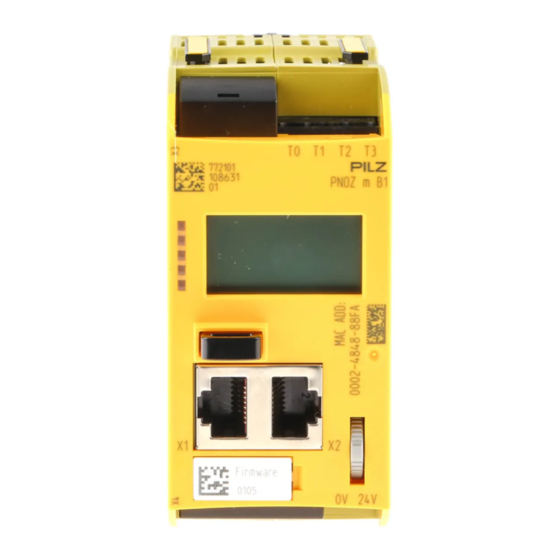
Page 8: Front View
To determine the version of the device, please note: The firmware version number is on the labelling clip. This is also the version number that must be selected in the PNOZmulti Configurator under Version during the hardware config- uration. Operating Manual PNOZ m B1 1003790-EN-02... -
Page 9: Safety
Inputs and outputs for standard functions must not be used for safety-re- lated applications. The product PNOZ m B1 meets the requirements of the standards EN 81-20, EN 81-22 and EN 81-50, harmonised under the Lifts Directive 2014/33/EU, and the requirements of the standard EN 115-1, harmonised under the Machinery Directive 2006/42/EC. -
Page 10: System Requirements
In safety-related applications, please comply with the mission time T in the safety-related characteristic data. When decommissioning, please comply with local regulations regarding the disposal of electronic devices (e.g. Electrical and Electronic Equipment Act). Operating Manual PNOZ m B1 | 10 1003790-EN-02... -
Page 11: For Your Safety
Adequate protection must be provided for all inductive consumers. Do not open the housing or make any unauthorised modifications. Please make sure you shut down the supply voltage when performing maintenance work (e.g. exchanging contactors). Operating Manual PNOZ m B1 | 11 1003790-EN-02... -
Page 12: Function Description
System reaction time Calculation of the maximum reaction time between an input switching off and a linked out- put in the system switching off is described in the document "PNOZmulti System Expan- sion". Operating Manual PNOZ m B1 | 12 1003790-EN-02... -
Page 13: Detection Of Shorts Across Contacts
Pulsing of test pulse outputs T0 ... T3 (typical times): 200 ms 4 ms 4 ms 6 ms 6 ms 4 ms 4 ms 6 ms 6 ms 4 ms 4 ms 6 ms 6 ms 4 ms 4 ms Operating Manual PNOZ m B1 | 13 1003790-EN-02... -
Page 14: Block Diagram
For more information refer to the document PNOZmulti2 Communication Interfaces and the Online Help for the PNOZmulti Configurator. Ethernet interface The product PNOZ m B1 has an Ethernet interface to Manage and download projects Read the diagnostic data Set virtual inputs for standard functions Read virtual outputs for standard functions. -
Page 15: Installation
(see diagram). The values stated for the mounting distances are minimum specifications. The ambient temperature in the control cabinet must not exceed the figure stated in the technical details. Air conditioning may otherwise be required. Operating Manual PNOZ m B1 | 15 1003790-EN-02... - Page 16 Installation Mounting distances: Operating Manual PNOZ m B1 | 16 1003790-EN-02...
-
Page 17: Dimensions In Mm
Install the base unit and expansion modules on the mounting rail in the order configured in the PNOZmulti Configurator and connect the units using the jumper supplied. Fit the terminator to the unconnected interfaces on the base unit and expansion module. Jumper Terminator Terminator Operating Manual PNOZ m B1 | 17 1003790-EN-02... - Page 18 Installation CAUTION! Only connect the base unit and expansion modules when the supply voltage is switched off. Operating Manual PNOZ m B1 | 18 1003790-EN-02...
-
Page 19: Commissioning
– Terminal 0 V: 0 V, Protect the supply voltage as follows: – Circuit breaker, characteristic C - 6 A – Blow-out fuse, slow, 6A CAUTION! Do not connect or disconnect expansion modules and terminators during operation. Operating Manual PNOZ m B1 | 19 1003790-EN-02... -
Page 20: Ethernet Interfaces
6.3.3 Interface configuration RJ45 socket Standard Crossover 8-pin TD+ (Transmit+) RD+ (Receive+) TD- (Transmit-) RD- (Receive-) RD+ (Receive+) TD+ (Transmit+) n.c. n.c. n.c. n.c. RD- (Receive-) TD- (Transmit-) n.c. n.c. n.c. n.c. Operating Manual PNOZ m B1 | 20 1003790-EN-02... -
Page 21: Rj45 Connection Cable
Appropriate design measures should be used to ensure that the plug-in connection is insensitive to in- creased mechanical stress (e.g. through shock, vibration). Such measures include fixed routing with strain relief, for example. Operating Manual PNOZ m B1 | 21 1003790-EN-02... -
Page 22: Use Usb Memory
Connect the computer containing the PNOZmulti Configurator to the base unit PNOZ m B1 via the Ethernet interface. Make sure that the USB memory is plugged into the base unit PNOZ m B1. Switch on the supply voltage. Operating Manual PNOZ m B1... -
Page 23: Activate Project Via The Display On The Base Unit
The menu settings are made on the device's display via a multifunction switch. You can switch between the menu levels by pressing or turning the multifunction switch. Press multifunction switch Confirm selection/setting Switch to sub-menu Exit menu: \.. Operating Manual PNOZ m B1 | 23 1003790-EN-02... -
Page 24: Displays And Settings
Hold the multifunction switch down for 4 s to confirm the selection or perform the action Press the multifunction switch to obtain information Press the multifunction switch to call up the system message Press the multifunction switch to call up the user message Operating Manual PNOZ m B1 | 24 1003790-EN-02... -
Page 25: Status Indicators
ST Run _systemMsg_ sages Diag _line2_ User message is present _line3_ Fault (user-specific messages that are created in the PNOZmulti Config- 12:00 x/n User FS urator) ST Run id:_display_ _element_ Diag _msg_ Fault Operating Manual PNOZ m B1 | 25 1003790-EN-02... -
Page 26: Project Menu
Check sum safe without level 3 DP pos y Checksums: safe F108 without L3 AB80 Project History: Project information is displayed for one of the last 16 projects activated Info Project history History Select Operating Manual PNOZ m B1 | 26 1003790-EN-02... - Page 27 After a reset, the active project is re- loaded from the USB memory Select Reset or update pro- Prerequisite: Device must be Reset ject. stopped Hold down multifunction switch for 4 s in order to reset Operating Manual PNOZ m B1 | 27 1003790-EN-02...
-
Page 28: Device Info Menu
Baseunit ted module: Product number: Order number 773200 Serial number Serial number 123456 Software versions Hardware version Operating hours Baseunit SW channels: 01.02 01.02 01.02 Baseunit 01.00 Baseunit Operating hours 1234 Operating Manual PNOZ m B1 | 28 1003790-EN-02... -
Page 29: Error Stack Menu
Display Example Description Operating Info Display of specific operating paramet- Pos Baseunit ers for the base unit and expansion FS cycl 10000us modules. FS cpu e.g.: cycle time, operating temperat- ure, frequencies Operating Manual PNOZ m B1 | 29 1003790-EN-02... -
Page 30: Connections Menu
Permission: Permission 1… 64 of the transpon- der key Security ID: Safety identifier of the transponder 6.7.2.7 Ethernet menu The Ethernet configuration can be displayed and changed in the Ethernet menu. Operating Manual PNOZ m B1 | 30 1003790-EN-02... - Page 31 Load Ethernet settings from the act- ive PNOZmulti project Use DHCP Change IP address Use program -> Hold down multifunction switch for Use default 2 s in order to perform the action Operating Manual PNOZ m B1 | 31 1003790-EN-02...
-
Page 32: Time Menu
It is essential to check that the safety devices operate correctly – After exchanging the USB memory – After activating a project – When the project was reset and reloaded from the USB memory fol- lowing a restart (Reset Project menu). Operating Manual PNOZ m B1 | 32 1003790-EN-02... -
Page 33: Operation
ST program is executed FS program in STOP condition ST program in STOP condition Error in FS program Error in ST program System error in FS program System error in ST program Operating Manual PNOZ m B1 | 33 1003790-EN-02... -
Page 34: Show Error Stack On The Display
Error parameter (EP) Procedure for showing the error stack on the display, see section entitled Error Stack menu. To evaluate the entries on the display please read the document PNOZmulti Error Mes- sages. Operating Manual PNOZ m B1 | 34 1003790-EN-02... -
Page 35: Technical Details
In accordance with the standard EN 60068-2-30, EN 60068-2-78 Humidity 93 % r. h. at 40 °C Condensation during operation Not permitted Max. operating height above sea level 2000 m EN 61131-2 Operating Manual PNOZ m B1 | 35 1003790-EN-02... - Page 36 0,2 - 2,5 mm², 24 - 12 AWG Spring-loaded terminals: Terminal points per connec- tion Stripping length with spring-loaded terminals 9 mm Dimensions Height 101,4 mm Width 45 mm Depth 120,2 mm Weight 209 g Operating Manual PNOZ m B1 | 36 1003790-EN-02...
-
Page 37: Safety Characteristic Data
A safety function's SIL/PL values are not identical to the SIL/PL values of the units that are used and may be different. We recommend that you use the PAScal software tool to calculate the safety function's SIL/PL values. Operating Manual PNOZ m B1 | 37 1003790-EN-02... -
Page 38: Order Reference
1 set of spring-loaded terminals 751 016 Set4 Screw Terminals 1 set of screw terminals 750 016 Jumper Product type Features Order No. USB Memory 512MB Pilz USB memory, 512 MB 779 213 Operating Manual PNOZ m B1 | 38 1003790-EN-02... - Page 39 Back cover Support Technical support is available from Pilz round the clock. Americas Australia Scandinavia Brazil +61 3 95600621 +45 74436332 +55 11 97569-2804 Spain Canada Europe +34 938497433 +1 888-315-PILZ (315-7459) Austria Switzerland Mexico +43 1 7986263-0 +41 62 88979-30...
Need help?
Do you have a question about the PNOZ m B1 and is the answer not in the manual?
Questions and answers