
Subscribe to Our Youtube Channel
Related Manuals for Pilz PNOZ mm0.2p


Summary of Contents for Pilz PNOZ mm0.2p
- Page 1 PNOZ mm0.2p Configurable, safe compact controllers PNOZmulti Mini Operating Manual-1002235-EN-07...
- Page 2 We do assure you that all persons are regarded without discrim- ination and on an equal basis. All rights to this documentation are reserved by Pilz GmbH & Co. KG. Copies may be made for the user's internal purposes. Suggestions and comments for improving this documenta- tion will be gratefully received.
-
Page 3: Table Of Contents
Commissioning the PNOZmulti safety system................6.2.3.1 Load project from chip card ...................... 21 6.2.3.2 Load project via USB port ......................21 6.2.4 Connection..........................6.2.5 Connection of two base units....................6.2.5.1 Interface assignment ........................ 24 6.2.5.2 Connection..........................24 Operating Manual PNOZ mm0.2p 1002235-EN-07... - Page 4 Maximum capacitive load C (μF) with load current I (A) at the semiconductor outputs.... Maximum permitted total current of the semiconductor outputs ..........Order reference ........................10.1 Product ............................. 10.2 Accessories ..........................EC declaration of conformity ....................UKCA-Declaration of Conformity ..................Operating Manual PNOZ mm0.2p 1002235-EN-07...
-
Page 5: Introduction
Introduction Introduction Validity of documentation This documentation is valid for the product PNOZ mm0.2p. It is valid until new documenta- tion is published. This operating manual explains the function and operation, describes the installation and provides guidelines on how to connect the product. - Page 6 Introduction INFORMATION This gives advice on applications and provides information on special fea- tures. Operating Manual PNOZ mm0.2p 1002235-EN-07...
-
Page 7: Overview
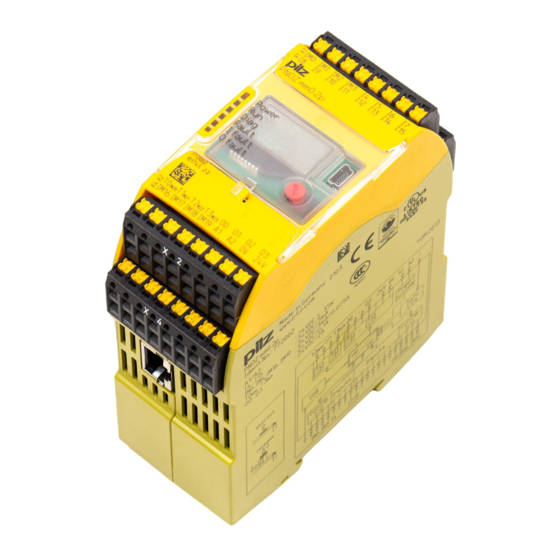
Range Base unit PNOZ mm0.2p Right-hand terminator: (yellow) Left-hand terminator: (yellow/black) Unit features Application of the product PNOZ mm0.2p: PNOZmulti Mini base unit The product has the following features: Can be configured in the PNOZmulti Configurator Semiconductor outputs: 4 safety outputs... -
Page 8: Chip Card
To be able to use the product you will need a chip card. Chip cards are available with memories of 8 kByte and 32 kByte. For large-scale projects we recommend the 32 kByte chip card (see Technical Catalogue: Accessories chapter). Operating Manual PNOZ mm0.2p 1002235-EN-07... -
Page 9: Front View
Semiconductor outputs O0 ... O3 Configurable inputs/outputs IM0 – IM3 Inputs I4 ... I7 Configurable inputs/outputs IM16 – IM19 Supply connections LEDs: DIAG FAULT I FAULT O FAULT Safe Link RJ45 RJ45 socket for connection of 2 base units Operating Manual PNOZ mm0.2p 1002235-EN-07... -
Page 10: Safety
EN ISO 13849 and EN 62061. However, this does not guarantee the functional safety of the overall plant/machine. To achieve the relevant safety level of the overall plant/ machine’s required safety functions, each safety function needs to be considered separ- ately. Operating Manual PNOZ mm0.2p | 10 1002235-EN-07... -
Page 11: Use Of Qualified Personnel
Adequate protection must be provided for all inductive consumers. Do not open the housing or make any unauthorised modifications. Please make sure you shut down the supply voltage when performing maintenance work (e.g. exchanging contactors). Operating Manual PNOZ mm0.2p | 11 1002235-EN-07... -
Page 12: Function Description
Data transmission time: The t data transmission time is the time between the virtual output at base unit 1 being set and the virtual input at base unit 2 becoming available (see "Technical details"). Operating Manual PNOZ mm0.2p | 12 1002235-EN-07... - Page 13 The risk assessment must consider all hazards as regards the reaction time and the safety distance. The overall reaction time must not delay the arrival of a safe condition by more than the permitted time. Operating Manual PNOZ mm0.2p | 13 1002235-EN-07...
-
Page 14: Diagnostics
24 V 0 V CA+ CA- CB+ CB- CGround A1 A2 RJ45 Configurable Safe Link Interface 24 V 0 V output Power Configurable Input input/output I12 I13 I14 I15 IM3IM16 IM17 IM18 IM19 Operating Manual PNOZ mm0.2p | 14 1002235-EN-07... -
Page 15: Installation
(see diagram). The values stated for the mounting distances are minimum specifications. The ambient temperature in the control cabinet must not exceed the figure stated in the technical details. Air conditioning may otherwise be required. Operating Manual PNOZ mm0.2p | 15 1002235-EN-07... -
Page 16: Dimensions
Installation Mounting distances: Dimensions *with spring-loaded terminals 98 (3.86") * 100 (3,94") (1.77") Operating Manual PNOZ mm0.2p | 16 1002235-EN-07... -
Page 17: Install Base Unit Without Expansion Module
– Left-hand side on the base unit and expansion modules to the left of the base unit: Black/yellow terminator – Right-hand side on the base unit and expansion modules to the right of the base unit: Yellow terminator Operating Manual PNOZ mm0.2p | 17 1002235-EN-07... - Page 18 Installation Jumper Left terminator Right terminator CAUTION! Only connect the base unit and expansion modules when the supply voltage is switched off. Operating Manual PNOZ mm0.2p | 18 1002235-EN-07...
-
Page 19: Commissioning
(see "Preparing for operation"). Note the crossover cabling, e.g. CA+ with CB+. The cables must be classified into a minimum of Category 5 in accordance with ISO/IEC 11801. Operating Manual PNOZ mm0.2p | 19 1002235-EN-07... -
Page 20: Preparing For Operation
– Mechanical impact, such as scratches. NOTICE Switch off the product before inserting or exchanging the chip card. Make sure that you do not bend the chip card as you insert it into the chip card slot. Operating Manual PNOZ mm0.2p | 20 1002235-EN-07... -
Page 21: Commissioning The Pnozmulti Safety System
Download the project (see PNOZmulti Configurator's online help). Once the project has been successfully downloaded, the status of the inputs and outputs and the supply voltage will be shown on the display. The "RUN" LED will be lit. Operating Manual PNOZ mm0.2p | 21 1002235-EN-07... -
Page 22: Connection
E-STOP with detection of shorts across contacts T1M21 T0M20 T0M20 Start circuit Input circuit without detection of Input circuit with detection of shorts across contacts shorts across contacts T0M20 Operating Manual PNOZ mm0.2p | 22 1002235-EN-07... - Page 23 Please note that, in the event of an error in the feedback loop, the safety system switches to a safe condition and shuts down all the outputs. Feedback loop Redundant output Contacts from external contactors O0 (O2) O1 (O3) Operating Manual PNOZ mm0.2p | 23 1002235-EN-07...
-
Page 24: Connection Of Two Base Units
Commissioning 6.2.5 Connection of two base units 6.2.5.1 Interface assignment RJ45 socket Layout 8-pin n.c. n.c. n.c. n.c. Shield CGround 6.2.5.2 Connection Connection of two base units PNOZmulti Mini via the integrated interface Operating Manual PNOZ mm0.2p | 24 1002235-EN-07... -
Page 25: Connection Examples
+ switch-off delay t of the semiconductor output at O1 COND + (n * t ) + t COND = 4 ms + (2 * 35 ms ) + 30 ms = 104 ms Operating Manual PNOZ mm0.2p | 25 1002235-EN-07... -
Page 26: Example 2: Connection Of 5 Base Units
O0 on Base 2: 69 ms O1 on Base 3: 104 ms O0 on Base 4: 139 ms O0 on Base 5: 104 ms I4 I6 I3 I6 Base 3 Base 1 Base 2 Base 4 Base 5 Operating Manual PNOZ mm0.2p | 26 1002235-EN-07... -
Page 27: Operation
The fieldbus module has not been recognised. The base unit was identified by the PNOZmulti Configur- ator via the Ethernet interface An existing fieldbus connection was interrupted. Operating Manual PNOZ mm0.2p | 27 1002235-EN-07... -
Page 28: Display Indicators
100 m yes/no (only appears on devices 3rd-4th line: Configured with an integrated interface cable length (100 m/1000 m) for connection of two base units) Operating Manual PNOZ mm0.2p | 28 1002235-EN-07... - Page 29 RESET PROJECT? Delete project from the base RESET PROJECT? unit's memory Delete project EXIT MENU? Exit menu EXIT MENU? Exit menu You can switch between the menu levels by pressing or rotating the knob. Operating Manual PNOZ mm0.2p | 29 1002235-EN-07...
-
Page 30: Rotary Knob
– Press the knob downwards [2] while keeping the bar pressed in 7.2.1.3 Rotate and press the knob The settings are made via the rotary knob, as follows: Press knob Confirm selection/setting Switch to menu Rotate knob Select menu level Operating Manual PNOZ mm0.2p | 30 1002235-EN-07... -
Page 31: Switch Between Menu Levels
Once the cause has been rectified, you will need to reset the unit Procedure for resetting the unit: Press the rotary knob for between 3 and 8 seconds to reset the unit. Operating Manual PNOZ mm0.2p | 31 1002235-EN-07... -
Page 32: Error Stack On The Lc Display
Error stack on the LC display The error stack can be read from the PNOZmulti Configurator or shown on the LC display. The error stack helps Pilz technical support with fault diagnostics. The error stack can store up to 64 status and error messages. - Page 33 Operation INFORMATION Use the rotary knob to exit the error stack. Procedure for reading the error stack with the PNOZmulti Configurator: See online help for the PNOZmulti Configurator Operating Manual PNOZ mm0.2p | 33 1002235-EN-07...
-
Page 34: Technical Details
Residual current at "0" 0,5 mA Voltage at "1" UB - 2 V at 0.1 A Virtual inputs Number of virtual inputs Inputs Number Signal level at "0" -3 - +5 V DC Operating Manual PNOZ mm0.2p | 34 1002235-EN-07... - Page 35 In accordance with the standard EN 60068-2-14 Temperature range 0 - 60 °C Forced convection in control cabinet off 55 °C Storage temperature In accordance with the standard EN 60068-2-1/-2 Temperature range -25 - 70 °C Operating Manual PNOZ mm0.2p | 35 1002235-EN-07...
- Page 36 Max. cable length per input 1 km Sum of individual cable lengths at the test pulse output 2 km Max. cable length between two link modules 1 km Material Bottom Front Connection type Spring-loaded terminal, screw terminal Operating Manual PNOZ mm0.2p | 36 1002235-EN-07...
-
Page 37: Safety Characteristic Data
SIL 2 3,46E-04 Inputs 2-channel PL e Cat. 4 SIL CL 3 4,61E-10 SIL 3 7,08E-06 Inputs Short cir- cuit-form- ing safety mats PL d Cat. 3 SIL CL 2 1,86E-09 SIL 2 9,62E-05 Operating Manual PNOZ mm0.2p | 37 1002235-EN-07... - Page 38 A safety function's SIL/PL values are not identical to the SIL/PL values of the units that are used and may be different. We recommend that you use the PAScal software tool to calculate the safety function's SIL/PL values. Operating Manual PNOZ mm0.2p | 38 1002235-EN-07...
-
Page 39: Supplementary Data
Maximum capacitive load C (μF) with load current I (A) at the semiconductor outputs C [µF] I [A] Maximum permitted total current of the semiconductor outputs [mA] : Total current of the configurable semiconductor outputs (auxiliary outputs) : Total current: Semiconductor outputs (safety outputs) Operating Manual PNOZ mm0.2p | 39 1002235-EN-07... -
Page 40: Order Reference
Left terminator, black/yellow, x1 779 261 left Cable Product type Features Order no. PSSu A USB-CAB03 Mini USB cable, 3 m 312 992 PSSu A USB-CAB05 Mini USB cable, 5 m 312 993 Operating Manual PNOZ mm0.2p | 40 1002235-EN-07... -
Page 41: Ec Declaration Of Conformity
European Parliament and of the Council. The complete EC Declaration of Conformity is available on the Internet at www.pilz.com/downloads. Authorised representative: Norbert Fröhlich, Pilz GmbH & Co. KG, Felix-Wankel-Str. 2, 73760 Ostfildern, Germany Operating Manual PNOZ mm0.2p... -
Page 42: Ukca-Declaration Of Conformity
This product(s) complies with following UK legislation: Supply of Machinery (Safety) Regu- lation 2008. The complete UKCA Declaration of Conformity is available on the Internet at www.pilz.com/ support/downloads. Representative: Pilz Automation Technology, Pilz House, Little Colliers Field, Corby, Northamptonshire, NN18 8TJ United Kingdom, eMail: mail@pilz.co.uk Operating Manual PNOZ mm0.2p | 42... - Page 43 We are represented internationally. Please refer to our homepage www.pilz.com for further details or contact our headquarters. Headquarters: Pilz GmbH & Co. KG, Felix-Wankel-Straße 2, 73760 Ostfildern, Germany Telephone: +49 711 3409-0, Telefax: +49 711 3409-133, E-Mail: info@pilz.com, Internet: www.pilz.com...
Need help?
Do you have a question about the PNOZ mm0.2p and is the answer not in the manual?
Questions and answers