Table of Contents
Advertisement
Quick Links
SL-865G / 865G-L
Chapter 1 Specification ............................................. 7
1-1 Mainboard Layout ................................................................... 8
1-2 Mainboard Specification Table ..............................................9
1-3 Chipset System Block Diagram ........................................... 10
1-4 Mainboard Specifications ..................................................... 11
1-4.1 CPU Socket ................................................................................... 11
1-4.2 System Chipsets ........................................................................... 11
1-4.3 Memory ......................................................................................... 11
1-4.4 AMI BIOS ..................................................................................... 11
1-4.5 Integrated Multiplexed AGP and DVO Interface .................. 12
1-4.6 Multi-I/O Functions .................................................................... 12
1-4.7 Expansion Slots ............................................................................ 12
1-4.8 Ethernet on board (865G-L only) ............................................. 13
1-4.9 Advanced System Power Management .................................... 13
1-4.10 Hardware Monitor on board ................................................... 13
1-4.11 AC'97 Audio Codec on board ................................................. 13
1-4.12 6-channel Audio-out Support (Optional) .............................. 13
1-4.13 Form Factor ................................................................................ 13
Chapter 2 Hardware Setup ..................................... 15
2-1 CPU Installation with Socket 478 ....................................... 16
2-1.1 To Identify a Pentium 4 CPU ..................................................... 16
2-1.2 CPU Installation with Socket 478 ............................................. 17
2-2 Pentium 4 CPU Fan Installation: ....................................... 18
2-3 Memory Installation ............................................................. 19
2-3.1 To Install DDR SDRAM Module .............................................. 19
2-3.2 Dual Channel Memory Features ............................................... 20
2-3.3 To Remove a DIMM .................................................................... 20
2-4 VGA / AGP 8X/4X Slot Installation .................................... 21
......................................................................................................... 22
2-5 IDE Connectors Installation ................................................ 23
2-6 Serial ATA Connectors Installation .................................... 24
2-7 Floppy Drive Connector Installation ................................. 25
2-8 ATX V2.03 Power Supply Installation ............................... 26
2-9 Jumper Settings ..................................................................... 27
Contents
4
Advertisement
Table of Contents

Related Manuals for SOLTEK SL-865G


Summary of Contents for SOLTEK SL-865G
-
Page 1: Table Of Contents
SL-865G / 865G-L Contents Chapter 1 Specification ..........7 1-1 Mainboard Layout ..............8 1-2 Mainboard Specification Table ..........9 1-3 Chipset System Block Diagram ........... 10 1-4 Mainboard Specifications ............. 11 1-4.1 CPU Socket ................... 11 1-4.2 System Chipsets ................11 1-4.3 Memory .................. - Page 2 Contents 2-9.1 JFSB1 & JFSB2: CPU Frequency Select ......... 28 2-9.2 JBAT1: Clear CMOS ..............29 2-9.3 JFSB3: Memory Turbo Mode ............ 30 2-9.4 LJP1: LAN Controller Select (865G-L only) ......30 2-9.5 JKB1: Keyboard / Mouse Wake Up ......... 31 2-10 Other Connectors Configuration ........
- Page 3 SL-865G / 865G-L 4-6.1 Main Menu in CMOS Setup Utility.......... 58 4-6.2 Standard BIOS Features ............60 4-6.3 Advanced BIOS Features ............61 4-6.3.1 CPU Configuration..............62 4-6.3.2 IDE Configuration ..............63 4-6.3.3 Floppy Configuration ............... 67 4-6.3.4 Super IO Configuration ............68 4-6.3.5 Hardware Health Configuration ..........
-
Page 4: Chapter 1 Specification
Chapter 1 Specification Chapter 1 Specification Introduction This series of mainboards features an integration of the powerful pro- cessor Intel Pentium 4 and the single-chip North Bridge Intel 865G. The Intel P4 processor is a rapid execution engine providing 800/533/ 400MHz system bus, while North Bridge Intel 865G is a high perfor- mance integrated chipset providing Dual Channel DDR 400/333/266 SDRAM memory interface, Hub interface and AGP interface as well as... -
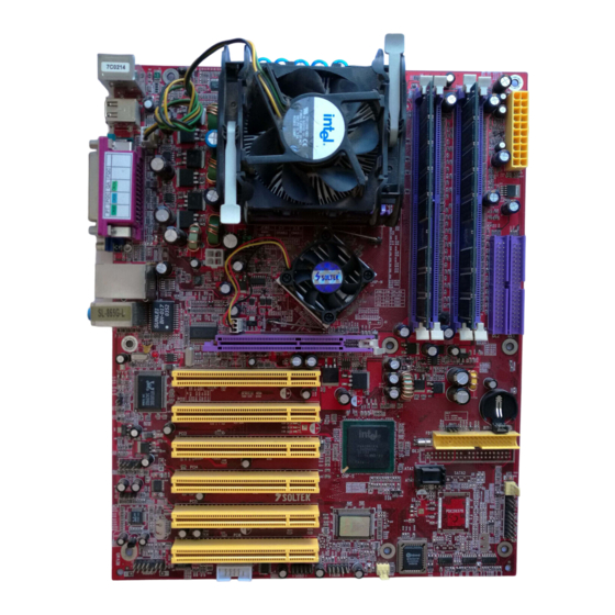
Page 5: Mainboard Layout
SL-865G / 865G-L 1-1 Mainboard Layout LJP1 for 865G-L only RTL8100C RJ45 JKB1 Main PS/2 Mouse Power (on top) PS/2 Keyboard USB0 ( port ) USB1 (port) Fan1 JFSB1 JFSB2 JFSB3 Intel +12V Power RJ45 Intel 82865 (on top) USB2 (port) -
Page 6: Mainboard Specification Table
Chapter 1 Specification 1-2 Mainboard Specification Table 865/865G-L Specifications and Features Socket 478B for P4 CPU( HT CPU included) (Hyper Threading CPU and Prescott CPU included) Intel 865G, 800/533/400MHz Front Side Bus North Bridge Intel ICH5 South Bridge BIOS AMI BIOS Dual Channel DDR 400/333/266 SDRAM, up to Memory 4GB in 4 DIMM slots... -
Page 7: Chipset System Block Diagram
SL-865G / 865G-L 1-3 Chipset System Block Diagram Intel Pentium 4 CPU (Hyper-Threading and Prescott CPU included) System Bus 800/533/400MHz DDR memory North Bridge Interface System Memory AGP 8X/4X DDR 400/ AGP Slot Intel 333/266 DVO(digital) 865G SDRAM TV Out... -
Page 8: Mainboard Specifications
Chapter 1 Specification 1-4 Mainboard Specifications 1-4.1 CPU Socket ® CPU Socket 478B on board, supporting Intel Pentium 4 processors (including Intel Hyper-Threading CPUs and Prescott CPUs) in 478-pin package for : -- 800/533/400MHz System Bus; 512KB L2 Advanced Transfer Cache -- Hyper-pipelined technology;... -
Page 9: 1-4.5 Integrated Multiplexed Agp And Dvo Interface
SL-865G / 865G-L 1-4.5 Integrated Multiplexed AGP and DVO Interface Integrated multiplexed AGP and DVO interface in 865G,supporting AGP performance and analog/Digital display: • one AGP slot on board, supporting both Digital Video Out card or AGP8x/4x card for analog/digital display (TMDS,LVDS and TV-out) (See AGP Installation in Chapter 2 of this manual) •... -
Page 10: 1-4.8 Ethernet On Board (865G-L Only)
• Hardware Monitor supported by W83627HF, providing monitoring and alarm for flexible desktop management of hardware voltage, tempera- tures and fan speeds. • Utility Software Soltek Hardware Monitor for displaying system status is enclosed in Support CD for user’s installation. 1-4.11 AC’97 Audio Codec on board AC’97 Audio Codec 2.2 compliant on board... - Page 11 SL-865G / 865G-L MEMO...
-
Page 12: Chapter 2 Hardware Setup
Chapter 2 Hardware Setup Chapter 2 Hardware Setup To Get Things Ready for Hardware Setup ! 1. We recommend to install your CPU before any other components. For detailed installation instructions of processor, you can also refer to the pamphlet enclosed in your CPU package. 2. -
Page 13: Cpu Installation With Socket 478
SL-865G / 865G-L 2-1 CPU Installation with Socket 478 2-1.1 To Identify a Pentium 4 CPU Intel PENTIUM 4 2.80 GHz / 512 / 800 (Hyper-Threading & Prescott CPU included) 3) System Bus 2) CPU L2 Cache 1) CPU Working Frequency On the heatsink side of a Pentium 4 CPU, there printed a line of figures to identify its specifications. -
Page 14: 2-1.2 Cpu Installation With Socket 478
Chapter 2 Hardware Setup 2-1.2 CPU Installation with Socket 478 This mainboard is built with CPU Socket 478B ( 478-pin) supporting the Intel Pentium 4 CPU: • Follow the steps described in this section to install the 478-pin Pen- tium 4 CPU into the on board Socket 478. -
Page 15: Pentium 4 Cpu Fan Installation
SL-865G / 865G-L 2-2 Pentium 4 CPU Fan Installation: Pentium 4 Fanbase CPU Fan Connector Press down 2 Spring Locks to lock fan to fanbase Connect Fan Connector to CPU FAN connector The above pictures are taken from sample mainboards as installation illustr-... -
Page 16: Memory Installation
Chapter 2 Hardware Setup 2-3 Memory Installation How to tackle the memory Modules: • Make sure to unplug your power supply before adding or removing memory module. • Pay attention to the orientation of the DIMM slots. 2-3.1 To Install DDR SDRAM Module •... -
Page 17: 2-3.2 Dual Channel Memory Features
SL-865G / 865G-L 2-3.2 Dual Channel Memory Features The Dual Channel DDR SDRAM installation is quite different from the Single channel installation. • Dual Channel memory configuration provides higher performance than Single Channel configurations • Matched DIMMs need to have identical density, DRAM technology, DRAM bus width, and equal number of memory banks. -
Page 18: Vga / Agp 8X/4X Slot Installation
Chapter 2 Hardware Setup 2-4 VGA / AGP 8X/4X Slot Installation 1. To install on-board VGA, please connect your monitor directly to VGA connector on board. 2. To install AGP 8X/4X card / Digital-Video-Out(DVO) / TV Out display, please insert an AGP / DVO /TV Out card into the AGP slot. This AGP slot supports AGP 8X/4X card(analog), DVO card and TV Out card, respectively but not simultaneously. - Page 19 SL-865G / 865G-L 3. Please note the AGP slot on board supports 1.5V AGP 8X/4X card only if users want to install a VGA card. A Rib is specifically added to the 8X/4X slot so as to match the AGP 8X/4X card. To insert a 3.3V AGP 2X card into the AGP 8X/4X slot will damage the system chip and burn the 1.5V circuitry.
-
Page 20: Ide Connectors Installation
Chapter 2 Hardware Setup 2-5 IDE Connectors Installation To install IDE Connector, you may connect the blue connector of IDE cable to the primary (IDE1) or secondary (IDE2) connector on board, and then connect the gray connector to your slave device and the black connector to your master device. -
Page 21: Serial Ata Connectors Installation
SL-865G / 865G-L 2-6 Serial ATA Connectors Installation The Serial ATA is designed to improve the Parallel ATA with the capabil- ity of Hot Plug and offer a data bandwidth of 150Mbytes/second. It also reduce voltage and pin count and can be implemented with thin cables which improve the inner ventilaton of PC cases. -
Page 22: Floppy Drive Connector Installation
Chapter 2 Hardware Setup 2-7 Floppy Drive Connector Installation To install FDC, you should connect the end of FDC cable with single connector to the board, and connect the other end with two connectors to the floppy drives. JKB1 Main PS/2 Mouse Power (on top) -
Page 23: Atx V2.03 Power Supply Installation
SL-865G / 865G-L 2-8 ATX V2.03 Power Supply Installation +12V Power Connector +12V PWR OK PS ON# +3.3V -12V JKB1 Main PS/2 Mouse Power (on top) PS/2 Keyboard +3.3V +3.3V USB0 ( port ) USB1 (port) Pin1 Pin11 Fan1 Main Power Connector... -
Page 24: Jumper Settings
Chapter 2 Hardware Setup 2-9 Jumper Settings The following diagrams show the locations and settings of jumper blocks on the mainboard. JFSB1&JFSB2: CPU Frequency Select JKB1: (default) Keyboard / Mouse Wake Up 100MHz 133MHz 200MHz Auto- (FSB400) (FSB533) (FSB800) Detection 1-2 closed (default) Disabled JFSB1... -
Page 25: 2-9.1 Jfsb1 & Jfsb2: Cpu Frequency Select
SL-865G / 865G-L How to tackle the Jumpers: A 2-pin Jumper A 3-pin Jumper If a pin-header (of 2 or more pins) is designed in such a way that its pins can be closed or linked together to The conductor inside the cap set up a specific function, this header links two header-pins together. -
Page 26: 2-9.2 Jbat1: Clear Cmos
Chapter 2 Hardware Setup Further Notes on CPU Overclocking: 1. If you have successfully booted system, with or without CPU overclock, you still can try another CPU overclock in BIOS Setup. Please enter BIOS Setup, choose “Frequency/Voltage Control” of Advanced BIOS Features, and configure the “CPU Clock” item to raise your CPU clock. -
Page 27: 2-9.3 Jfsb3: Memory Turbo Mode
SL-865G / 865G-L 2-9.3 JFSB3: Memory Turbo Mode JFSB3 is designed on board for improving Memory performance. If you want to obtain better system performance, you can set JFSB3 2-3 closed to enable the Memory Turbo Mode. Otherwise, you can set JFSB3 1-2 closed to disable the Memory Turbo Mode. -
Page 28: 2-9.5 Jkb1: Keyboard / Mouse Wake Up
Chapter 2 Hardware Setup 2-9.5 JKB1: Keyboard / Mouse Wake Up JKB1 is designed on board as a jumper to enable/disable the PS/2 key- board/mouse Wake Up from suspend mode. USB keyboard/mouse Wake Up function is optionally supported on this mainboard. -
Page 29: Other Connectors Configuration
SL-865G / 865G-L 2-10 Other Connectors Configuration This section lists out all connectors configurations for users’ reference. 2-10.1 On Board Fan Connectors Void JKB1 Main Sensor PS/2 Mouse Power (on top) PS/2 Keyboard +12V USB0 ( port ) +12V USB1 (port) Fan1 Sensor Conn. -
Page 30: 2-10.2 Usb Ports And Usb Pin-Headers
Chapter 2 Hardware Setup 2-10.2 USB Ports and USB Pin-headers This series provides four USB ports USB0 to USB3 on board support- ing various USB devices. In addition, two USB pin-headers are added on board to provide expansion of four more optional USB ports by us- ing two additional USB cables. -
Page 31: 2-10.3 Chassis Panel Connectors
SL-865G / 865G-L 2-10.3 Chassis Panel Connectors A : PS/2 Mouse H : COM1 Connector B : USB 0 (top) : VGA Connector C : LPT1 Port : USB 2 (middle) D : RJ45 (865G-L only) USB 3 (underside) E : Line in/... -
Page 32: 2-10.5 Cd-Rom Audio Connectors
Chapter 2 Hardware Setup 2-10.5 CD-ROM Audio Connectors CD-IN1 is an audio connector connecting CD-ROM audio to mainboard. JKB1 Main PS/2 Mouse Power (on top) PS/2 Keyboard USB0 ( port ) USB1 (port) Fan1 CD-ROM Audio Pin Assignment JFSB1 JFSB2 JFSB3 Intel RJ45... -
Page 33: 2-10.7 External Audio Connector
SL-865G / 865G-L JKB1 Main 2-10.7 External Audio Connector PS/2 Mouse Power (on top) PS/2 Keyboard USB0 ( port ) USB1 (port) Fan1 This Mainboard is designed with a External Audio connector “CN3” which provides con- JFSB1 JFSB2 JFSB3 nection to your chassis. -
Page 34: 2-10.9 Complex Pin-Header
Chapter 2 Hardware Setup 2-10.9 Complex Pin-header This complex Pin-header consists of the following connectors for vari- ous supports. When you have fixed the mainboard to the case, join the connectors of this Complex Pin-header to the case Front Panel. JKB1 Main PS/2 Mouse... - Page 35 SL-865G / 865G-L (1) Power Switch Connector: Connection: Connected to a momentary button or switch. Function: Manually switching the system between “On” and “Soft Off”. Pressing the momentary button for more than 4 seconds will also turn the system off.
-
Page 36: 2-10.10 Thermal Resistor
Chapter 2 Hardware Setup 2-10.10 Thermal Resistor JKB1 Main PS/2 Mouse Power (on top) PS/2 Keyboard USB0 ( port ) USB1 (port) Fan1 Thermal Resistor RT1 JFSB1 JFSB2 JFSB3 Intel RJ45 +12V Power Intel 82865 (on top) USB2 (port) 865G USB3 (port) Fan4 AGP 8X/4X... -
Page 37: Chapter 3 Software Setup
SL-865G / 865G-L Chapter 3 Software Setup Drivers, Utilities and Software Installation • Support CD: This series of mainboards will be shipped with a Support CD which contains those necessary driver files, Application Softwares and some helpful utilities. It is a user-friendly, auto-run CD which will open itself up in a CD-ROM automatically. -
Page 38: To Open Up The Support Cd
Chapter 3 Software Setup 3-1 To Open up the Support CD 1. Please put the Support CD enclosed in your mainboard package into the CD-ROM drive. In a few seconds, the Main Menu will automatic- ally appear, displaying the contents to be installed for this series: Intel Chipset Software installation utility DirectX Install Acrobat Reader... -
Page 39: Intel Chipset Software Installation Utility
SL-865G / 865G-L 3-2 Intel Chipset Software Installation Utility 1. Following the procedures of opening the Support CD, click to “ Install Intel Chipset software installation Utility” to proceed. 2. The Intel Service Pack InstallShield Wizard will pop up to guide you to the Intel Service pack installation. -
Page 40: Directx Installation
Chapter 3 Software Setup 3-3 DirectX Installation Following the installation of INF, you have to restart system so that your system can be reconfigured with the driver just installed. When restarting procedures finish, please open the Support CD with your CD- ROM to enter the Main Installation Menu. -
Page 41: Graphics Driver Installation
SL-865G / 865G-L 3-4 Graphics Driver Installation Following the installation of IAA, you have to restart system so that your system can be reconfigured with the utility. When restarting pro- cedures finish, please open the Support CD with your CD-ROM to en- ter the Main Installation Menu. -
Page 42: Ac'97 Audio Driver Installation
Chapter 3 Software Setup 3-5 AC’97 Audio Driver Installation Avance AC97 Audio Codec on board, AC’97 2.2 compatible stereo audio code for PC multimedia systems. Avance AC’97 Audio Codec Driver is pro- vided in Support CD for user’s installation. 3-5.1 Install AC’97 6-channel Audio Driver 1. -
Page 43: 3-5.2 Verify 6-Channel Audio
SL-865G / 865G-L 3-5.2 Verify 6-channel Audio After installation of AC’97 6-channel Codec, you must configure the 5.1 Speaker connection to enable the 6-channel audio. 1. Connect your on-board Audio Connector to your 6-channel speakers as depicted in the figure below:... - Page 44 Chapter 3 Software Setup 3. The AC’97 Audio Configuration” screen will pop out. Clikc the “Speaker Configuration” bar with your mouse. 4. Instantly, the “Speaker Configuration” screen will pop out. Pick the items “6-channel mode for 5.1 speakers output” and “ Synchronize the phonejack switch with the speakers settings”...
- Page 45 SL-865G / 865G-L 5. At finishing the Speakers Configuration, you can also click the “Speaker Test” bar on the screen to test the 6-channel performance. The figure below is the “Speaker Test” screen with testing instructions enclosed on it. Follow the instructions to perform the Speakers Test.
-
Page 46: To Install Hardware Monitor Utility
Chapter 3 Software Setup 3-6 To Install Hardware Monitor Utility 3-6.1 Installation Hardware Monitor is built on this mainboard. Its installation is pro- grammed to a fully automated mode on Windows 9X/Me/NT4/2000/ XP. Users can follow the model installation below for its installation on various Windows System. -
Page 47: 3-6.2 Verification
SL-865G / 865G-L 3-6.2 Verification 1. After installing Soltek Hardware Monitor, double click “SoltekHM” icon on the desktop to open the main window of the Soltek Hardware Doctor. 2.Then the pop-up screen will show all information about CPU Temperature, Fan Speed and various Voltages. -
Page 48: To Install Lan Drivers (For 865G-L Only)
Chapter 3 Software Setup 3-7 To Install LAN Drivers (for 865G-L only) 3-7.1 Installation 1. Following the procedures of opening the Support CD, click to “ Onboard LAN Driver” to proceed. 2. Instantly, “The installation is completed” screen appears, indicating that LAN Driver setup is finished. -
Page 49: To Install Usb 2.0 Driver For Windows 2000/Xp
SL-865G / 865G-L 3-8 To Install USB 2.0 Driver for Windows 2000/XP USB V2.0 with its 480Mb/s transfer rate supports operating system Windows 2000 and Windows XP via the Windows 2000 and Windows XP Service Pack. For archieving Intel USB 2.0 support, users should install the latest Service Pack for Windows 2000 or Windows XP. - Page 50 Chapter 3 Software Setup MEMO...
-
Page 51: Chapter 4 Ami Bios Setup
4-5 To Update BIOS 4-6 BIOS Setup Attention: The BIOS Setup is subject to constant update without further notice to users. It is necessary for users to update the onboard BIOS by the latest BIOS version provided in our web site: www.soltek.com.tw... -
Page 52: About Bios Setup
Chapter 4 BIOS Setup 4-1 About BIOS Setup BIOS setup is an interactive BIOS program that you need to run when: 1. Changing the hardware of your system. (For example: installing a new Hard Disk etc.) 2. Modifying the behavior of your computer. (For example: changing the system time or date, or turning special features on or off etc.) 3. -
Page 53: To Update Bios
SL-865G / 865G-L 4-5 To Update BIOS • System BIOS is incorporated into a Flash memory component. Flash BIOS allows user to upgrade BIOS without the need to replace an EPROM component. • The Upgrade Utility can be loaded on a floppy diskette for upgrading saving, and verifying the system BIOS. - Page 54 Chapter 4 BIOS Setup Step 4. Under “ A “ prompt, type “ amiflash *.ROM “ and then press <Enter> to run BIOS update program. (*.ROM depends on your mainboard model and version code. Instead of typing “*”, you should type the specific file name for your specific mainboard).
-
Page 55: Bios Setup By Cmos Setup Utility
SL-865G / 865G-L 4-6 BIOS SETUP by CMOS Setup Utility 4-6.1 Main Menu in CMOS Setup Utility This mainboard comes with the AMI BIOS from American Megatrends Inc. Enter the CMOS Setup Utility Main Menu by: 1. Turn on or reboot your system. After a series of diagnostic checks, the following message will appear: PRESS <Del>... - Page 56 <F9>: “Optimized Defaults” allows user to load Optimal Defaults or not. Attention: The BIOS Setup is subject to constant update without further notice to users. It is necessary for users to update the onboard BIOS by the latest BIOS version provided in our web site: www.soltek.com.tw...
-
Page 57: 4-6.2 Standard Bios Features
SL-865G / 865G-L 4-6.2 Standard BIOS Features “Standard BIOS Features” allows users to configure Time and Date. This menu also displays system information. Run the Standard BIOS Features as follows: Choose “Standard BIOS Features” from the Main Menu and press <Enter>. -
Page 58: 4-6.3 Advanced Bios Features
Chapter 4 BIOS Setup 4-6.3 Advanced BIOS Features Advanced BIOS Features allows user to configure HDD, Floppy, Serial Port, Parallel Port etc..Run the Advanced BIOS Features as follows: Choose “Advanced BIOS Features” from the Main Menu and a screen with a list of options will appear: CMOS Setup Utility - Copyright (C) 1985-2002, American Megatrends, Inc. -
Page 59: 4-6.3.1 Cpu Configuration
SL-865G / 865G-L 4-6.3.1 CPU Configuration Choose “CPU Configuration” in “Advanced BIOS Features” and press <Enter>. The following sub-screen will appear for configuration: CPU Configuration Help Item Configure advanced CPU settings Sets the ratio between CPU Manufacturer : Intel core clock and the FSB Brand String : Intel(R) Pentium (R) 4 CPU 1500MHz Frequency. -
Page 60: 4-6.3.2 Ide Configuration
Chapter 4 BIOS Setup 4-6.3.2 IDE Configuration Choose “IDE Configuration” in “Advanced BIOS Features” and press <Enter>. The following sub-screen will appear for IDE Devices configuration: IDE Configuration Help Item IDE Configuration IDE Configuration P/S-ATA (Auto) S-ATA Running Enhanced Mode P-ATA Channel Selection Both S-ATA Ports Definition... - Page 61 SL-865G / 865G-L 4-6.3.2-1 IDE Configuration IDE Configuration Allows you to configurare IDE device mode. Choices: P/S-ATA(Auto): Parallel/Serial ATA combined mode; S-ATA Only: For S-ATA running on board only; P/S-ATA(Win98/Me): P/S-ATA on Win98/Me only Disabled: IDE Configuration disabled IDE Configuration Choosing “P/S-ATA(Auto)”...
- Page 62 Chapter 4 BIOS Setup 4-6.3.2-2 Primary/Secondary IDE Master/Slave and Third/Fourth IDE Master Primary IDE Master Hard Disk Primary IDE Slave ATAPI CDROM Secondary IDE Master Not Detected Secondary IDE Slave Not Detected Third IDE Master Not Detected Fourth IDE Master Not Detected Press <Enter>...
- Page 63 SL-865G / 865G-L 4-6.3.2-3 Hard Disk Write Protect Hard Disk Write Allows you to Enabled / Disable(default) Hard Disk Protect Write Protection 4-6.3.2-4 IDE Detect Time Out IDE Detect Time Out Allows you to set time out for IDE Detection.
-
Page 64: 4-6.3.3 Floppy Configuration
Chapter 4 BIOS Setup 4-6.3.3 Floppy Configuration 1. Choose “Floppy Configuration” in “Advanced BIOS Features” and press <Enter>. The following sub-screen will appear for configuration: Floppy Configuration Help Item Floppy Configuration Floppy A 1.44 MB 3.5 in Select the type of floppy Floppy B Disabled drive connected to the... -
Page 65: 4-6.3.4 Super Io Configuration
SL-865G / 865G-L 4-6.3.4 Super IO Configuration Choose “SuperIO Configuration” in “Advanced BIOS Features” and press <Enter>. The following sub-screen will appear for configuration: SuperIO Configuration Help Item Configure Win627 Super IO Chipset OnBoard Floppy Controller Enabled Allows BIOS to Enable or... - Page 66 Chapter 4 BIOS Setup OnBoard CIR Port Allows you to set the onboard CIR Port. Choices: Disabled; 2E0; 3E0 Parallel Port Address Allows you to configure Parallel Port Address. Choices: Disabled; 378; 278; 3BC; C.S.A Gigabit Ethernet Allows you to disable C.S.A Gigabit Ethernet Choices: Auto(default);...
-
Page 67: 4-6.3.5 Hardware Health Configuration
SL-865G / 865G-L 4-6.3.5 Hardware Health Configuration Choose “Hardware Health Configuration” in “Advanced BIOS Features” and press <Enter>. The following sub-screen will appear for configuration: Hardware Health Configuration Hardware Health Configuration Help Item System Temperature : 34˚C/93˚F Enables Hardware Health Monitoring Device. -
Page 68: 4-6.3.6 Acpi Configuration
Chapter 4 BIOS Setup 4-6.3.6 ACPI Configuration Choose “ACPI Configuration” in “Advanced BIOS Features” and press <Enter>. The following sub-screen will appear for ACPI configuration: ACPI Configuration Help Item ACPI Settings Enables Hardware ACPI ACPI Aware O/S support for Operating System. - Page 69 SL-865G / 865G-L Advanced ACPI Configuration: To press< Enter > on Advanced ACPI Configuration will reveal the following item(s). ACPI 2.0 Support Allows you to enable / disable ACPI (Advanced Con- figuration and Power Interface) 2.0 Support function. Choices: Yes; No ACPI APIC Support Allows you to enable / disable ACPI APIC (Advanced Programmable Interrupt Controller) Support function.
-
Page 70: 4-6.3.7 Usb Configuration
Chapter 4 BIOS Setup 4-6.3.7 USB Configuration Choose “USB Configuration” in “Advanced BIOS Features” and press <Enter>. The following sub-screen will appear for configuration: USB Configuration Help Item USB Configuration Enable USB host Module Version - 2.23.2-7.4 controllers. USB Devices Enabled : None USB Function 8 USB Ports... - Page 71 SL-865G / 865G-L USB Mass Storage Press “Enter” to view its submenu shown below. Device Config USB Mass Storage To select number of seconds POST waits for the Reset Delay USB mass storage device after start unit command. Choices: 10 Sec; 20 Sec; 30 Sec; 40 Sec...
-
Page 72: 4-6.3.8 Frequency/Voltage Control
Chapter 4 BIOS Setup 4-6.3.8 Frequency/Voltage Control Choose “Frequency/Voltage Control” in “Advanced BIOS Features” and press <Enter>. The following sub-screen will appear for configuration: Frequency/Voltage Control Help Item Frequency/Voltage Configuration Press “+”/”-” to select. CPU Linear Frequency Enabled CPU Clock 100MHz Fix AGP/PCI Frequency Enabled... -
Page 73: 4-6.3.9 Power Management
SL-865G / 865G-L 4-6.3.9 Power Management Choose “Power Management” in “Advanced BIOS Features” and press <Enter>. The following sub-screen will appear for configuration: Power Management Help Item APM Configuration Enable or disable APM. Power Management/APM Enabled Video Power Down Mode... - Page 74 Chapter 4 BIOS Setup Power Button Function Allows you to set power Button function. Choices: On/Off (default); Suspend Restore on AC/Power Allows you to set the restore state from AC/Power Loss Loss. Choices: Last State; Power Off (default); Power On Resume on Ring Allows you to enable / disable (default)the Resume on Ring Signal function.
-
Page 75: 4-6.4 Advanced Chipset Features
SL-865G / 865G-L 4-6.4 Advanced Chipset Features Advanced Chipset Features is used to modify the values of chipset buffers. These buffers control the system options. Run the Advanced Chipset Features as follows: Choose “Advanced Chipset Features” from the Main Menu and a list of option will appear: CMOS Setup Utility - Copyright (C) 1985-2002, American Megatrends, Inc. -
Page 76: 4-6.4.1 Northbridge Configuration
Chapter 4 BIOS Setup 4-6.4.1 NorthBridge Configuration Choose “NorthBridge Configuration” in “Advanced Chipset Features” and press <Enter>. The following sub-screen will appear for configuration: NorthBridge Configuration Help Item DRAM Frequency Auto Configure DRAM Timing by SPD Enabled Memory Hole Disabled Init. - Page 77 SL-865G / 865G-L DRAM CAS# Latency With SDRAM Timing by SPD disabled, you can se- lect the SDRAM CAS# (Column Address Strode)la- tency manually. Choices: 2 Clocks; 2.5 Clocks; 3 Clocks DRAM RAS# With SDRAM Timing by SPD disabled, you can se-...
- Page 78 Chapter 4 BIOS Setup Boot Display Device Allows you to select the Boot Display device. Choices: Auto (default); CRT; TV; EFP; LFP; CRT+EFP; CRT+LFP Flat Panel Type Allows you to select the flat panel type. Choices: 640x480LVDS;800x600LVDS; 1024x768LVDS; 1280x1024LVDS; 1400x1050LVDS;1600x1200LVDS; 640x480CMOS;...
-
Page 79: 4-6.4.2 Southbridge Configuration
SL-865G / 865G-L 4-6.4.2 SouthBridge Configuration 1. Choose “SouthBridge Configuration” in “Advanced Chipset Fea- tures” and press <Enter>. The following sub-screen will appear for configuration: SouthBridge Configuration Help Item OnBoard AC’97 Audio Auto : Move Enter : Select +/- : Values... -
Page 80: 4-6.5 Pci/Pnp Resource Management
Chapter 4 BIOS Setup 4-6.5 PCI/PNP Resource Management PCI/PNP Resource Management allows you to modify the system’s power saving functions. Choose “PCI/PNP Resource Management” from the Main Menu and a screen with a list of options will appear: CMOS Setup Utility - Copyright (C) 1985-2002, American Megatrends, Inc. PCI/PNP Resource Management Help Item Advanced PCI/PNP Settings... - Page 81 SL-865G / 865G-L Palette Snooping This option allows the BIOS to preview VGA status, and to modify the information delivered from the feature Connector of the VGA card to MPEG card. This option can solve the display inversion to black after you have used a MPEG card.
-
Page 82: 4-6.6 Boot Configuration Setup
Chapter 4 BIOS Setup 4-6.6 Boot Configuration Setup Boot Configuration Setup allows you to modify the system’s boot settings. Choose “Boot Configuration Setup” from the Main Menu and a screen with a list of options will appear: CMOS Setup Utility - Copyright (C) 1985-2002, American Megatrends, Inc. Boot Configuration Setup Help Item Boot Settings... -
Page 83: 4-6.6.1 Boot Settings Configuration
SL-865G / 865G-L 4-6.6.1 Boot Settings Configuration Choose “Boot Settings Configuration” in “Boot Configuration Setup” and press <Enter>. The following items will appear for onfiguration: Boot Configuration Setup Help Item Boot Settings Configure Settings Quick Boot Enabled during System Boot. -
Page 84: 4-6.6.2 Boot Device Priority
Chapter 4 BIOS Setup 4-6.6.2 Boot Device Priority Choose “Boot Device Priority” in “Boot Configuration Setup” and press <Enter>. The bootable devices installed on board will appear and are allowed to assign the Boot Priority. Boot Device Priority Help Item Boot Device Priority Configure Settings 1st Boot Device... -
Page 85: 4-6.7 Boot Security Features
SL-865G / 865G-L 4-6.7 Boot Security Features Boot Security Features allows you to modify the system’s boot security settings. Choose “Boot Security Features” from the Main Menu and a screen with a list of options will appear: CMOS Setup Utility - Copyright (C) 1985-2002, American Megatrends, Inc. -
Page 86: 4-6.7.3 Change Supervisor Password
Chapter 4 BIOS Setup 4-6.7.3 Change Supervisor Password This option allows you to set a new Supervisor password for the system: 1. Choose “Change Supervisor Password” in the “BIOS Security Fea- tures” and press <Enter>. Then the following message appears: [ Enter new supervisor password ] 2. -
Page 87: 4-6.7.4 Change User Password
SL-865G / 865G-L 4-6.7.4 Change User Password This option allows you to set a new User password for the system: 1. Choose “Change User Password” in the “BIOS Security Features” and press <Enter>. Then the following message appears: [ Enter New Password ] 2. -
Page 88: 4-6.7.6 Boot Sector Virus Protection
Chapter 4 BIOS Setup Password Check Allows you to set BIOS to check up password with a password prompt at BIOS Setup or whenever re- starting system. This option will appear when you have set Supervisor Password or User Password. Choices: Setup (default);... -
Page 89: 4-6.9 Discard Changes ( And Exit )
SL-865G / 865G-L 4-6.9 Discard Changes ( and Exit ) Discard Changes option allows you to exit (or not exit) the Setup Utility without saving the modifications that you have specified. Highlight this option on the Main Menu and press <Enter> and the following message...
Need help?
Do you have a question about the SL-865G and is the answer not in the manual?
Questions and answers