Table of Contents
Advertisement
Quick Links
SL-865G3 / 865G3-L
Chapter 1 Specification ............................................. 6
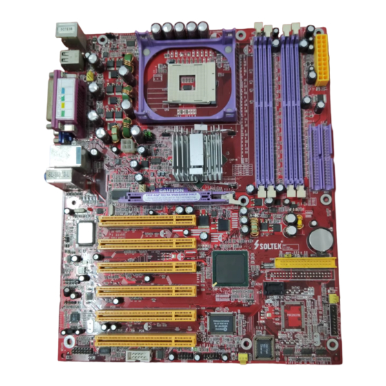
1-1 Mainboard Layout ................................................................... 7
1-2 Mainboard Specification Table ..............................................8
1-3 Mainboard Specifications ....................................................... 9
1-3.1 CPU Socket ..................................................................................... 9
1-3.2 System Chipsets ............................................................................. 9
1-3.3 Memory ........................................................................................... 9
1-3.4 AMI BIOS ....................................................................................... 9
1-3.5 Integrated Multiplexed AGP and DVO Interface .................. 10
1-3.6 Multi-I/O Functions .................................................................... 10
1-3.7 Expansion Slots ............................................................................ 10
1-3.8 Ethernet on board (865G3-L only) ........................................... 11
1-3.9 Hardware Monitor on board ..................................................... 11
1-3.10 AC'97 Audio Codec on board ................................................. 11
1-3.11 Form Factor ................................................................................ 11
1-3.12 Optional features ....................................................................... 11
Chapter 2 Hardware Setup ..................................... 12
2-1 CPU and CPU Fan Installation with Socket 478B ........... 12
2-1.1 CPU Installation with Socket 478B .......................................... 12
2-1.2 Hyper-threading CPU supported by Win XP ......................... 12
2-2 Memory Installation ............................................................. 13
2-2.1 To Install DDR SDRAM Module .............................................. 13
2-2.2 Dual Channel Memory Features ............................................... 13
2-3 VGA / AGP 8X/4X Slot Installation .................................... 14
2-4 IDE Connectors Installation ................................................ 15
2-5 Floppy Drive Connector Installation ................................. 16
2-6 Serial ATA Connectors Setup .............................................. 16
2-7 ATX V2.03 Power Supply Installation ............................... 17
2-8 On Board Fan Connectors ................................................... 17
2-9 Jumper Settings ..................................................................... 18
2-9.1 JFSB1 & JFSB2: CPU Frequency Select ................................. 19
2-9.2 JBAT1: Clear CMOS .................................................................. 20
2-9.3 JFSB3: Memory Turbo Mode .................................................... 21
2-9.4 LJP1: LAN Controller Select (865G3-L only) ........................ 21
2-9.5 JKB1: Keyboard / Mouse Wake Up ......................................... 21
Contents
4
Contents
Advertisement
Table of Contents

Related Manuals for SOLTEK SL-865G3


Summary of Contents for SOLTEK SL-865G3
-
Page 1: Table Of Contents
SL-865G3 / 865G3-L Contents Contents Chapter 1 Specification ..........6 1-1 Mainboard Layout ..............7 1-2 Mainboard Specification Table ..........8 1-3 Mainboard Specifications ............9 1-3.1 CPU Socket ..................9 1-3.2 System Chipsets ................9 1-3.3 Memory ................... 9 1-3.4 AMI BIOS ..................9 1-3.5 Integrated Multiplexed AGP and DVO Interface .... - Page 2 SL-865G3 / 865G3-L Contents 2-10 Other connectors setup ............22 2-10.1 Back Panel Connectors ............. 22 2-10.2 LAN Connector ................22 2-10.3 CD-ROM Audio Connectors ............ 23 2-10.4 External Audio Connector ............23 2-10.5 Complex Pin-header (Front Connectors) ......24 2-10.6 USB Ports and USB Pin-headers ..........
-
Page 3: Chapter 1 Specification
SL-865G3 / 865G3-L Chapter 1 Specification Chapter 1 Specification Introduction This series of mainboards features an integration of the powerful pro- cessor Intel Pentium 4 and the single-chip North Bridge Intel 865G. The Intel P4 processor is a rapid execution engine providing 800/533/... -
Page 4: Mainboard Layout
SL-865G3 / 865G3-L Chapter 1 Specification 1-1 Mainboard Layout LJP1 for 865G3-L only RTL8100C RJ45 JKB1 Main PS/2 Mouse Power (on top) PS/2 Keyboard USB0 (port) USB1 (port) Fan1 JFSB1 JFSB2 JFSB3 Intel RJ45 +12V Power Intel 82865 (on top) -
Page 5: Mainboard Specification Table
SL-865G3 / 865G3-L Chapter 1 Specification 1-2 Mainboard Specification Table 865G3/865G3-L Specifications and Features Socket 478B for P4 CPU (Hyper Threading and Prescott CPUs included) Intel 865G, 800/533/400MHz Front Side Bus North Bridge South Bridge Intel ICH5 BIOS AMI BIOS... -
Page 6: Mainboard Specifications
SL-865G3 / 865G3-L Chapter 1 Specification 1-3 Mainboard Specifications 1-3.1 CPU Socket ® CPU Socket 478B on board, supporting Intel Pentium 4 processors 3.4GHz(+) (including Intel Hyper-Threading and Prescott CPUs) in 478- pin package for : -- 800/533/400MHz System Bus; 512KB L2 Advanced Transfer Cache -- Hyper-pipelined technology;... -
Page 7: 1-3.5 Integrated Multiplexed Agp And Dvo Interface
SL-865G3 / 865G3-L Chapter 1 Specification 1-3.5 Integrated Multiplexed AGP and DVO Interface Integrated multiplexed AGP and DVO interface in 865G,supporting AGP performance and analog/Digital display: • one AGP slot on board, supporting both Digital Video Out card or AGP8x/4x card for analog/digital display (TMDS,LVDS and TV-out) (See AGP Installation in Chapter 2 of this manual) •... -
Page 8: 1-3.8 Ethernet On Board (865G3-L Only)
• Hardware Monitor supported by W83627HF, providing monitoring and alarm for flexible desktop management of hardware voltage, tempera- tures and fan speeds. • Utility Software Soltek Hardware Monitor for displaying system status is enclosed in Support CD for user’s installation. 1-3.10 AC’97 Audio Codec on board AC’97 Audio Codec 2.2 compliant on board... -
Page 9: Chapter 2 Hardware Setup
SL-865G3 / 865G3-L Chapter 2 Hardware Setup Chapter 2 Hardware Setup 2-1 CPU and CPU Fan Installation with Socket 478B 2-1.1 CPU Installation with Socket 478B (1) Pentium 4 CPU (2) Pull up the lever and insert P4 CPU into socket 478... -
Page 10: Memory Installation
SL-865G3 / 865G3-L Chapter 2 Hardware Setup 2-2 Memory Installation How to tackle the memory Modules: • Make sure to unplug your power supply before adding or removing memory module. • Pay attention to the orientation of the DIMM slots. -
Page 11: Vga / Agp 8X/4X Slot Installation
SL-865G3 / 865G3-L Chapter 2 Hardware Setup 2-3 VGA / AGP 8X/4X Slot Installation 1. To install on-board VGA, please connect your monitor directly to VGA connector on board. 2. To install AGP 8X/4X card / Digital-Video-Out(DVO) / TV Out display, please insert an AGP / DVO /TV Out card into the AGP slot. -
Page 12: Ide Connectors Installation
SL-865G3 / 865G3-L Chapter 2 Hardware Setup 2-4 IDE Connectors Installation To install IDE Connector, you may connect the blue connector of IDE cable to the primary (IDE1) or secondary (IDE2) connector on board, and then connect the gray connector to your hard disk. If you install two hard disks, you must configure the second drive to Slave mode by set- ting its jumpers correctly. -
Page 13: Floppy Drive Connector Installation
SL-865G3 / 865G3-L Chapter 2 Hardware Setup 2-5 Floppy Drive Connector Installation To install FDC, you should connect the end of FDC cable with single connector to the board, and connect the other end with two connectors to the floppy drives. -
Page 14: Atx V2.03 Power Supply Installation
SL-865G3 / 865G3-L Chapter 2 Hardware Setup 2-7 ATX V2.03 Power Supply Installation JKB1 Main PS/2 Mouse Power (on top) +12V PS/2 Keyboard USB0 (port) USB1 (port) +12V Power Fan1 PWR OK connector JFSB1 JFSB2 JFSB3 Intel RJ45 +12V Power... -
Page 15: Jumper Settings
SL-865G3 / 865G3-L Chapter 2 Hardware Setup 2-9 Jumper Settings The following diagrams show the locations and settings of jumper blocks on the mainboard. JFSB1&JFSB2: CPU Frequency Select JKB1: (default) Keyboard / Mouse Wake Up 100MHz 133MHz 200MHz Auto- (FSB400) -
Page 16: 2-9.1 Jfsb1 & Jfsb2: Cpu Frequency Select
SL-865G3 / 865G3-L Chapter 2 Hardware Setup How to tackle the Jumpers: A 2-pin Jumper A 3-pin Jumper If a pin-header (of 2 or more pins) is designed in such a way that its pins can be closed or linked together to... -
Page 17: 2-9.2 Jbat1: Clear Cmos
SL-865G3 / 865G3-L Chapter 2 Hardware Setup Further Notes on CPU Overclocking: 1. If you have successfully booted system, with or without CPU overclock, you still can try another CPU overclock in BIOS Setup. Please enter BIOS Setup, choose “Frequency/Voltage Control” of Advanced BIOS Features, and configure the “CPU Clock”... -
Page 18: 2-9.3 Jfsb3: Memory Turbo Mode
SL-865G3 / 865G3-L Chapter 2 Hardware Setup 2-9.3 JFSB3: Memory Turbo Mode JFSB3 JFSB3 is designed on board for improving Memory Turbo Mode Memory performance. If you want to obtain better system performance, you can set 1-2 closed (default) JFSB3 2-3 closed to enable the Memory Turbo Mode Disabled Turbo Mode. -
Page 19: Other Connectors Setup
SL-865G3 / 865G3-L Chapter 2 Hardware Setup 2-10 Other connectors setup 2-10.1 Back Panel Connectors A : PS/2 Mouse H : COM1 Connector B : USB 0 (top) : VGA Connector C : LPT1 Port : USB 2 (middle) D : RJ45 (865G3-L only) -
Page 20: 2-10.3 Cd-Rom Audio Connectors
SL-865G3 / 865G3-L Chapter 2 Hardware Setup 2-10.3 CD-ROM Audio Connectors CD-IN1 is an audio connector connecting CD-ROM audio to mainboard. 2-10.4 External Audio Connector This Mainboard is designed with an External Audio connector “JAUD1” which provides connection to your chassis. -
Page 21: 2-10.5 Complex Pin-Header (Front Connectors)
SL-865G3 / 865G3-L Chapter 2 Hardware Setup 2-10.5 Complex Pin-header (Front Connectors) This complex Pin-header consists of the following connectors for vari- ous supports. When you have fixed the mainboard to the case, join the connectors of this Complex Pin-header to the case Front Panel. -
Page 22: 2-10.6 Usb Ports And Usb Pin-Headers
SL-865G3 / 865G3-L Chapter 2 Hardware Setup 2-10.6 USB Ports and USB Pin-headers This series provides four USB ports on board supporting various USB devices. In addition, two USB pin-headers are added on board to pro- vide expansion of four more optional USB ports by using two additional USB cables. -
Page 23: Chapter 3 Software Setup
Chapter 3 Software Setup SL-865G3 / 865G3-L Chapter 3 Software Setup Drivers, Utilities and Software Installation • Support CD: This series of mainboards will be shipped with a Support CD which contains those necessary driver files, Application Softwares and some helpful utilities. -
Page 24: To Open Up The Support Cd
SL-865G3 / 865G3-L Chapter 3 Software Setup 3-1 To Open up the Support CD 1. Please put the Support CD enclosed in your mainboard package into the CD-ROM drive. In a few seconds, the Main Menu will automatic- ally appear, displaying the contents to be installed for this series:... -
Page 25: Intel Chipset Software Installation Utility
Chapter 3 Software Setup SL-865G3 / 865G3-L 3-2 Intel Chipset Software Installation Utility 1. Following the procedures of opening the Support CD, click to “ Install Intel Chipset software installation Utility” to proceed. 2. The Intel Service Pack I n s t a l l S h i e l d W i z a r d w i l l pop up to guide you to the Intel Service pack installation. -
Page 26: Graphics Driver Installation
SL-865G3 / 865G3-L Chapter 3 Software Setup 3-4 Graphics Driver Installation 1. For installation of on-board VGA driver, you must first connect the monitor to the on-board VGA connector. Then click to “Install Graphics Driver”. The Graphics Driver is specifically for on-board VGA. -
Page 27: 3-5.2 Verify 6-Channel Audio
Chapter 3 Software Setup SL-865G3 / 865G3-L 3. In a few seconds, the setup process is finished. Please check the radial button “Yes, I want to restart my computer now.” And click “Finish” to restart your system. Finish 3-5.2 Verify 6-channel Audio After installation of AC’97 6-channel Codec, you must configure the 5.1... - Page 28 SL-865G3 / 865G3-L Chapter 3 Software Setup 3. The AC’97 Audio Configuration” screen will pop out. Clikc the “Speaker Configuration” bar with your mouse. 4 . I n s t a n t l y , t h e “ S p e a k e r Configuration”...
-
Page 29: To Install Hardware Monitor Utility
Chapter 3 Software Setup SL-865G3 / 865G3-L 3-6 To Install Hardware Monitor Utility 3-6.1 Installation Hardware Monitor is built on this mainboard. Its installation is pro- grammed to a fully automated mode on Windows 9X/Me/NT4/2000/ XP. Users can follow the model installation below for its installation on various Windows System. -
Page 30: 3-6.2 Verification
SL-865G3 / 865G3-L Chapter 3 Software Setup 3-6.2 Verification 1. After installing Soltek Hardware Monitor, double click “SoltekHM” icon on the desktop to open the main window of the Soltek Hardware Doctor. 2.Then the pop-up screen will show all information about CPU Temperature, Fan Speed and various Voltages. -
Page 31: To Install Lan Drivers (For 865G3-L Only)
Chapter 3 Software Setup SL-865G3 / 865G3-L 3-7 To Install LAN Drivers (for 865G3-L only) 3-7.1 Installation 1. Following the procedures of opening the Support CD, click to “ Onboard LAN Driver” to proceed. 2. Instantly, “The installation is completed” screen appears, indicating that LAN Driver setup is finished. -
Page 32: To Install Usb 2.0 Driver For Windows 2000/Xp
SL-865G3 / 865G3-L Chapter 3 Software Setup 3-8 To Install USB 2.0 Driver for Windows 2000/XP USB V2.0 with its 480Mb/s transfer rate supports operating system Windows 2000 and Windows XP via the Windows 2000 and Windows XP Service Pack. For archieving Intel USB 2.0 support, users should install the latest Service Pack for Windows 2000 or Windows XP. -
Page 33: Chapter 4 Ami Bios Setup
4-5 To Update BIOS 4-6 BIOS Setup Attention: The BIOS Setup is subject to constant update without further notice to users. It is necessary for users to update the onboard BIOS by the latest BIOS version provided in our web site: www.soltek.com.tw... -
Page 34: About Bios Setup
SL-865G3 / 865G3-L Chapter 4 BIOS Setup 4-1 About BIOS Setup BIOS setup is an interactive BIOS program that you need to run when: 1. Changing the hardware of your system. (For example: installing a new Hard Disk etc.) 2. Modifying the behavior of your computer. (For example: changing the system time or date, or turning special features on or off etc.) -
Page 35: To Update Bios
SL-865G3 / 865G3-L Chapter 4 BIOS Setup 4-5 To Update BIOS • System BIOS is incorporated into a Flash memory component. Flash BIOS allows user to update BIOS without replacing an EPROM component. • The Update BIOS Utility “AMIflash.EXE” is a Flash EPROM Program- ming utility that can be loaded on a floppy diskette or a hard disk drive for updating BIOS. -
Page 36: Bios Setup By Cmos Setup Utility
SL-865G3 / 865G3-L Chapter 4 BIOS Setup 4-6 BIOS SETUP by CMOS Setup Utility 4-6.1 Main Menu in CMOS Setup Utility This mainboard comes with the AMI BIOS from American Megatrends Inc. Enter the CMOS Setup Utility Main Menu by: 1. - Page 37 <F9>: “Optimized Defaults” allows user to load Optimal Defaults or not. Attention: The BIOS Setup is subject to constant update without further notice to users. It is necessary for users to update the onboard BIOS by the latest BIOS version provided in our web site: www.soltek.com.tw...
-
Page 38: 4-6.2 Standard Bios Features
SL-865G3 / 865G3-L Chapter 4 BIOS Setup 4-6.2 Standard BIOS Features “Standard BIOS Features” allows users to configure Time and Date. This menu also displays system information. Run the Standard BIOS Features as follows: Choose “Standard BIOS Features” from the Main Menu and press <Enter>. -
Page 39: 4-6.3 Advanced Bios Features
SL-865G3 / 865G3-L Chapter 4 BIOS Setup 4-6.3 Advanced BIOS Features Advanced BIOS Features allows user to configure HDD, Floppy, Serial Port, Parallel Port etc..Run the Advanced BIOS Features as follows: Choose “Advanced BIOS Features” from the Main Menu and a screen with a list of options will appear: CMOS Setup Utility - Copyright (C) 1985-2002, American Megatrends, Inc. - Page 40 SL-865G3 / 865G3-L Chapter 4 BIOS Setup 4-6.3.1 CPU Configuration Choose “CPU Configuration” in “Advanced BIOS Features” and press <Enter>. The following sub-screen will appear for configuration: CPU Configuration Help Item Configure advanced CPU settings Sets the ratio between CPU...
- Page 41 SL-865G3 / 865G3-L Chapter 4 BIOS Setup 4-6.3.2 IDE Configuration Choose “IDE Configuration” in “Advanced BIOS Features” and press <Enter>. The following sub-screen will appear for IDE Devices configuration: IDE Configuration Help Item IDE Configuration IDE Configuration P/S-ATA (Auto) S-ATA Running Enhanced Mode...
- Page 42 SL-865G3 / 865G3-L Chapter 4 BIOS Setup 4-6.3.2-1 IDE Configuration IDE Configuration Allows you to configurare IDE device mode. Choices: P/S-ATA(Auto): Parallel/Serial ATA combined mode; S-ATA Only: For S-ATA running on board only; P/S-ATA(Win98/Me): P/S-ATA on Win98/Me only Disabled: IDE Configuration disabled IDE Configuration Choosing “P/S-ATA(Auto)”...
- Page 43 SL-865G3 / 865G3-L Chapter 4 BIOS Setup 4-6.3.2-2 Primary/Secondary IDE Master/Slave and Third/Fourth IDE Master Primary IDE Master Hard Disk Primary IDE Slave ATAPI CDROM Secondary IDE Master Not Detected Secondary IDE Slave Not Detected Third IDE Master Not Detected...
- Page 44 SL-865G3 / 865G3-L Chapter 4 BIOS Setup 4-6.3.2-3 Hard Disk Write Protect Hard Disk Write Allows you to Enabled / Disable(default) Hard Disk Protect Write Protection 4-6.3.2-4 IDE Detect Time Out IDE Detect Time Out Allows you to set time out for IDE Detection.
- Page 45 SL-865G3 / 865G3-L Chapter 4 BIOS Setup 4-6.3.4 Super IO Configuration Choose “SuperIO Configuration” in “Advanced BIOS Features” and press <Enter>. The following sub-screen will appear for configuration: SuperIO Configuration Help Item Configure Win627 Super IO Chipset OnBoard Floppy Controller...
- Page 46 SL-865G3 / 865G3-L Chapter 4 BIOS Setup OnBoard CIR Port Allows you to set the onboard CIR Port. Choices: Disabled; 2E0; 3E0 Parallel Port Address Allows you to configure Parallel Port Address. Choices: Disabled; 378; 278; 3BC; C.S.A Gigabit Ethernet Allows you to disable C.S.A Gigabit Ethernet Choices: Auto(default);...
- Page 47 SL-865G3 / 865G3-L Chapter 4 BIOS Setup 4-6.3.5 Hardware Health Configuration Choose “Hardware Health Configuration” in “Advanced BIOS Features” and press <Enter>. The following sub-screen will appear for configuration: Hardware Health Configuration Hardware Health Configuration Help Item Enables Hardware Health System Temperature : 34˚C/93˚F...
- Page 48 SL-865G3 / 865G3-L Chapter 4 BIOS Setup 4-6.3.6 ACPI Configuration Choose “ACPI Configuration” in “Advanced BIOS Features” and press <Enter>. The following sub-screen will appear for ACPI configuration: ACPI Configuration Help Item ACPI Settings Enables Hardware ACPI ACPI Aware O/S support for Operating System.
- Page 49 SL-865G3 / 865G3-L Chapter 4 BIOS Setup Advanced ACPI Configuration: To press< Enter > on Advanced ACPI Configuration will reveal the following item(s). ACPI 2.0 Support Allows you to enable / disable ACPI (Advanced Con- figuration and Power Interface) 2.0 Support function.
- Page 50 SL-865G3 / 865G3-L Chapter 4 BIOS Setup USB Function Allows you to set the USB Function on the USB port (s). Choices: 8 USB Ports; Disabled Legacy USB Support Allows you to enable / disable the Legacy USB support. Choices: Enabled; Disabled; Auto USB 2.0 Controller Allows you to enable/ disable the USB 2.0 Controller.
- Page 51 SL-865G3 / 865G3-L Chapter 4 BIOS Setup 4-6.3.8 Frequency/Voltage Control Choose “Frequency/Voltage Control” in “Advanced BIOS Features” and press <Enter>. The following sub-screen will appear for configuration: Frequency/Voltage Control Help Item Frequency/Voltage Configuration Press “+”/”-” to select. CPU Linear Frequency...
- Page 52 SL-865G3 / 865G3-L Chapter 4 BIOS Setup 4-6.3.9 Power Management Choose “Power Management” in “Advanced BIOS Features” and press <Enter>. The following sub-screen will appear for configuration: Power Management Help Item APM Configuration Enable or disable APM. Power Management/APM Enabled...
-
Page 53: 4-6.4 Advanced Chipset Features
SL-865G3 / 865G3-L Chapter 4 BIOS Setup Resume on Ring Allows you to enable / disable (default)the Resume on Ring Signal function. An input signal on the serial Ring Indicator (RI) Line (in other words, an incoming call on the modem) awakens the system from a soft off state. - Page 54 SL-865G3 / 865G3-L Chapter 4 BIOS Setup 4-6.4.1 NorthBridge Configuration Choose “NorthBridge Configuration” in “Advanced Chipset Features” and press <Enter>. The following sub-screen will appear for configuration: NorthBridge Configuration Help Item DRAM Frequency Auto Configure DRAM Timing by SPD Enabled...
- Page 55 SL-865G3 / 865G3-L Chapter 4 BIOS Setup DRAM Precharge Allows you to set the SDRAM Precharge Delay Delay cycle. Choices: 5 Clocks; 6 Clocks; 7 Clocks; 8 Clocks DRAM Burst Length With SDRAM Timing by SPD disabled, you can se- lect the SDRAM Burst length manually.
-
Page 56: 4-6.5 Pci/Pnp Resource Management
SL-865G3 / 865G3-L Chapter 4 BIOS Setup 4-6.4.2 SouthBridge Configuration 1. Choose “SouthBridge Configuration” in “Advanced Chipset Fea- tures” and press <Enter>. The following sub-screen will appear for configuration: SouthBridge Configuration Help Item OnBoard AC’97 Audio Auto Onboard AC‘97 Audio Allows you to disable AC’ 97 Audio. - Page 57 SL-865G3 / 865G3-L Chapter 4 BIOS Setup Plug & Play O/S Allows you to configure the PNP devices by BIOS or O/S. Choices: No(by BIOS) (default); Yes(by O/S) Allows you to set the PCI Latency Time. PCI Latency Timer (PCI Choices: 32(default);...
-
Page 58: 4-6.6 Boot Configuration Setup
SL-865G3 / 865G3-L Chapter 4 BIOS Setup 4-6.6 Boot Configuration Setup Boot Configuration Setup allows you to modify the system’s boot settings. Choose “Boot Configuration Setup” from the Main Menu and a screen with a list of options will appear: CMOS Setup Utility - Copyright (C) 1985-2002, American Megatrends, Inc. - Page 59 SL-865G3 / 865G3-L Chapter 4 BIOS Setup Bootup Num-lock Allows you to toggle between On (default) or Off to control the state of the NumLock keys when the system boots. If On, the numeric keypad is in nu- meric mode. If off, the numeric keypad is in cursor control mode.
-
Page 60: 4-6.7 Boot Security Features
SL-865G3 / 865G3-L Chapter 4 BIOS Setup 4-6.7 Boot Security Features Boot Security Features allows you to modify the system’s boot security settings. Choose “Boot Security Features” from the Main Menu and a screen with a list of options will appear: CMOS Setup Utility - Copyright (C) 1985-2002, American Megatrends, Inc. - Page 61 SL-865G3 / 865G3-L Chapter 4 BIOS Setup 4-6.7.3 Change Supervisor Password This option allows you to set a new Supervisor password for the system: 1. Choose “Change Supervisor Password” in the “BIOS Security Fea- tures” and press <Enter>. Then the following message appears: [ Enter new supervisor password ] 2.
- Page 62 SL-865G3 / 865G3-L Chapter 4 BIOS Setup 4-6.7.4 Change User Password This option allows you to set a new User password for the system: 1. Choose “Change User Password” in the “BIOS Security Features” and press <Enter>. Then the following message appears: [ Enter New Password ] 2.
-
Page 63: 4-6.8 Save Changes And Exit
SL-865G3 / 865G3-L Chapter 4 BIOS Setup Password Check Allows you to set BIOS to check up password with a password prompt at BIOS Setup or whenever re- starting system. This option will appear when you have set Supervisor Password or User Password. -
Page 64: 4-6.9 Discard Changes ( And Exit )
SL-865G3 / 865G3-L Chapter 4 BIOS Setup 4-6.9 Discard Changes ( and Exit ) Discard Changes option allows you to exit (or not exit) the Setup Utility without saving the modifications that you have specified. Highlight this option on the Main Menu and press <Enter> and the following message...
Need help?
Do you have a question about the SL-865G3 and is the answer not in the manual?
Questions and answers