Mitsubishi Electric FR-A520-0.4K Instruction Manual
Hide thumbs
Also See for FR-A520-0.4K:
- Instruction manual (228 pages) ,
- Instruction manual (228 pages) ,
- Instruction manual (225 pages)
Table of Contents
Advertisement
TRANSISTORIZED INVERTER
FR-A
500
INSTRUCTION MANUAL
FR-A520-0.4K to 55K
FR-A540-0.4K to 55K
HIGH FUNCTION
&
LOW ACOUSTIC NOISE
Get other manuals https://www.bkmanuals.com
OUTLINE
INSTALLATION
AND WIRING
OPERATION
/CONTROL
PARAMETERS
PROTECTIVE
FUNCTIONS
PRECAUTIONS FOR
MAINTENANCE AND
INSPECTION
SPECIFICATIONS
OPTIONS
Chapter 1
Chapter 2
Chapter 3
Chapter 4
Chapter 5
Chapter 6
Chapter 7
Chapter 8
Advertisement
Table of Contents

Related Manuals for Mitsubishi Electric FR-A520-0.4K


Summary of Contents for Mitsubishi Electric FR-A520-0.4K
- Page 1 TRANSISTORIZED INVERTER FR-A INSTRUCTION MANUAL HIGH FUNCTION OUTLINE Chapter 1 & LOW ACOUSTIC NOISE INSTALLATION FR-A520-0.4K to 55K Chapter 2 AND WIRING FR-A540-0.4K to 55K OPERATION Chapter 3 /CONTROL PARAMETERS Chapter 4 PROTECTIVE Chapter 5 FUNCTIONS PRECAUTIONS FOR Chapter 6...
- Page 2 Thank you for choosing this Mitsubishi transistorized Inverter. This instruction manual gives handling information and precautions for use of this equipment. Incorrect handling might cause an unexpected fault. Before using the inverter, please read this manual carefully to use the equipment to its optimum.
- Page 3 4. Additional instructions Also note the following points to prevent an accidental failure, injury, electric shock, etc. (1) Transportation and installation CAUTION When carrying products, use correct lifting gear to prevent injury. Do not stack the inverter boxes higher than the number recommended. Ensure that installation position and material can withstand the weight of the inverter.
- Page 4 (5) Emergency stop CAUTION Provide a safety backup such as an emergency brake which will prevent the machine and equipment from hazardous conditions if the inverter fails. When the breaker on the inverter primary side trips, check for the wiring fault (short circuit), damage to the internal parts of the inverter, etc.
-
Page 5: Table Of Contents
CONTENTS CHAPTER 1 OUTLINE Pre-Operation Information .................. 2 1.1.1 Precautions for operation ........................2 Basic Configuration ..................... 3 1.2.1 Basic configuration ..........................3 Structure ....................... 4 1.3.1 Appearance and structure ........................4 1.3.2 Removal and reinstallation of the front cover ..................5 1.3.3 Removal and reinstallation of the operation panel ................7 CHAPTER 2 INSTALLATION AND WIRING Installation ...................... - Page 6 3.3.3 PU operation mode (Operation using the operation panel (FR-DU04)) ................61 3.3.4 Combined operation mode (Operation using the external input signals and PU)................62 CHAPTER 4 PARAMETERS Parameter Lists ....................64 4.1.1 Parameter lists ..........................64 4.1.2 List of parameters classified by purpose of use ................71 4.1.3 Parameters recommended to be set by the user ................72 Parameter Function Details ................
- Page 7 4.2.43 Commercial power supply-inverter switch-over function (Pr. 135 to Pr. 139) ........148 4.2.44 Output current detection function (Pr. 150, Pr. 151)...............153 4.2.45 Zero current detection (Pr. 152, Pr. 153)..................154 4.2.46 RT signal activated condition selection (Pr. 155) ................155 4.2.47 Stall prevention function and current limit function (Pr. 156)............155 4.2.48 OL signal output timer (Pr.
- Page 8 6.1.3 Periodic inspection .........................210 6.1.4 Insulation resistance test using megger ..................211 6.1.5 Pressure test ..........................211 6.1.6 Daily and periodic inspection......................211 6.1.7 Replacement of parts ........................214 6.1.8 Inverter replacement ........................215 6.1.9 Measurement of main circuit voltages, currents and powers ............216 CHAPTER 7 SPECIFICATIONS Standard Specifications ..................
- Page 9 Get other manuals https://www.bkmanuals.com...
-
Page 10: Outline
CHAPTER 1 OUTLINE Chapter 1 This chapter gives information on the basic "outline" of this product. Always read the instructions in this chapter before using the equipment. Chapter 2 1.1 Pre-Operation Information........2 1.2 Basic Configuration ..........3 1.3 Structure..............4 Chapter 3 <Abbreviations>... -
Page 11: Pre-Operation Information
Unpack the inverter and check the capacity plate on the front cover and the rating plate on the inverter side face to ensure that the product agrees with your order and the inverter is intact. 1) Inverter type Capacity plate Rating plate MITSUBISHI INVERTER MODEL FR-A520-0.4K Inverter type Input rating INPUT XXXXX FR-A520-0.4K Output rating OUTPUT :... -
Page 12: Basic Configuration
Ministry of Economy, Trade and Industry (formerly Ministry of International Trade and Industry) in September, 1994. This guideline applies to the FR-A520-0.4K to 3.7K. By installing the power factor improving reactor (FR-BEL or FR-BAL), this product complies the "harmonic suppression technique for transistorized inverters (input current 20A or less)"... -
Page 13: Structure
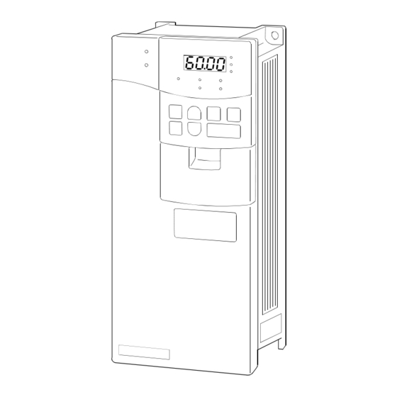
OUTLINE 1.3 Structure 1.3.1 Appearance and structure (1) Front view (2) Without front cover POWER lamp PU connector ALARM lamp (Provided with modular jack type relay connector) (For use with RS-485 cable communication) Modular jack type relay connector compartment Operation panel (FR-DU04) Brake resistor* (Fitted to the back) Inboard option mounting positions Accessory cover... -
Page 14: Removal And Reinstallation Of The Front Cover
OUTLINE 1.3.2 Removal and reinstallation of the front cover FR-A520-0.4K to 11K, FR-A540-0.4K to 7.5K • Removal 1) Hold both sides of the front cover top and push the front cover down. 2) Hold down the front cover and pull it toward you to remove. - Page 15 OUTLINE FR-A520-30K to 55K, FR-A540-30K to 55K • Removal 1) Remove installation screws on the front cover. • Reinstallation 1) Fix the front cover with the installation screws. Note: 1. Fully make sure that the front cover has been reinstalled securely. 2.
-
Page 16: Removal And Reinstallation Of The Operation Panel
OUTLINE 1.3.3 Removal and reinstallation of the operation panel To ensure safety, remove and reinstall the operation panel after powering off. • Removal Hold down the top button of the operation panel and pull the operation panel toward you to remove. Removal Reinstallation When reinstalling the operation panel, insert it straight and reinstall it securely. - Page 17 MEMO Get other manuals https://www.bkmanuals.com...
-
Page 18: Installation And Wiring
CHAPTER 2 INSTALLATION AND WIRING Chapter 1 This chapter explains the basic "installation and wiring" for use of this product. Always read the instructions and other information before using Chapter 2 the equipment. 2.1 Installation ............. 10 2.2 Wiring ..............12 2.3 Other wiring ............ -
Page 19: Installation
INSTALLATION AND WIRING 2.1 Installation 2.1.1 Instructions for installation 1) Handle the unit carefully. The inverter uses plastic parts. Handle it gently to protect it from damage. Also, hold the unit with even strength and do not apply too much strength to the front cover alone. 2) Install the inverter in a place where it is immune to vibration. - Page 20 INSTALLATION AND WIRING 8) For installation in an enclosure Ventilation fan Inverter Inverter Inverter Inverter Inverter Inverter Built-in cooling fan (Incorrect example) (Incorrect example) (Correct example) (Correct example) Position of Ventilation Fan Accommodation of two or more inverters 9) Vertical mounting (1) Wiring cover and handling (22K or less) 1) When cable conduits are not connected Cut the protective bushes of the wiring cover with nippers or a cutter before running the cables.
-
Page 21: Wiring
INSTALLATION AND WIRING 2.2 Wiring 2.2.1 Terminal connection diagram Motor -phase AC power supply connector Earth (Ground) Jumper Jumper Remove this jumper when using FR-BEL. 24VDC power output and external transistor common (Contact input common for source logic) (Note) Jumper (Note) Remove this jumper when using FR-ABR. - Page 22 INSTALLATION AND WIRING (1) Description of main circuit terminals Symbol Terminal Name Description Connect to the commercial power supply. Keep these terminals open when using the high R, S, T AC power input power factor converter (FR-HC) and power regeneration common converter (FR-CV). U, V, W Inverter output Connect a three-phase squirrel-cage motor.
- Page 23 • Overall length : 500m Terminals PR and PX are provided for the FR-A520-0.4K to 7.5K, FR-A540-0.4K to 7.5K. Low indicates that the open collector outputting transistor is on (conducts). High indicates that the transistor is off (does not conduct).
-
Page 24: Wiring Of The Main Circuit
INSTALLATION AND WIRING 2.2.2 Wiring of the main circuit (1) Wiring instructions 1) Crimping terminals with insulation sleeves are recommended for use with the power and motor cables. 2) Cut the protective bushes of the wiring cover when running the cables. (22K or less) 3) Power must not be applied to the output terminals (U, V, W) of the inverter. - Page 25 INSTALLATION AND WIRING 9) Do not install a power capacitor, surge suppressor or radio noise filter (FR-BIF option) in the output side of the inverter. This will cause the inverter to trip or the capacitor and surge suppressor to be damaged. If any of the above devices are installed, immediately remove them.
- Page 26 INSTALLATION AND WIRING (2) Terminal block layout In the main circuit of the inverter, the terminals are arranged as shown below: 1) 200V class FR-A520-0.4K, 0.75K FR-A520-15K, 18.5K, 22K Screw size (M4) Screw size (M4) N/– Charge lamp Charge lamp...
- Page 27 INSTALLATION AND WIRING 2) 400V class FR-A540-0.4K, 0.75K, 1.5K, 2.2K, 3.7K FR-A540-30K Screw size (M4) N/– Charge lamp Screw size (M6) Screw size (M4) N/– Charge lamp Jumper Screw size (M4) Screw size (M6) Jumper FR-A540-5.5K, 7.5K FR-A540-37K, 45K, 55K Screw size (M4) Screw size (M4) Charge lamp...
- Page 28 The following table lists the cables and crimping terminals used with the inputs (R, S, T) and outputs (U, V, W) of the inverter and the torques for tightening the screws: • FR-A520-0.4K to 55K HIV Cables (Note 1) Terminal...
- Page 29 R1 and S1 are available. In this case, connect the power supply terminals R1 and S1 of the control circuit to the primary side of the MC. • Model FR-A520-0.4K to 3.7K, FR-A540-0.4K to 3.7K <Connection procedure>...
-
Page 30: Wiring Of The Control Circuit
INSTALLATION AND WIRING 2.2.3 Wiring of the control circuit (1) Wiring instructions 1) Terminals SD, SE and 5 are common to the I/O signals and isolated from each other. Do not earth (ground) these terminals. Avoid connecting the terminals SD and 5 and the terminals SE and 5. 2) Use shielded or twisted cables for connection to the control circuit terminals and run them away from the main and power circuits (including the 200V relay sequence circuit). - Page 31 INSTALLATION AND WIRING (3) Changing the control logic The input signals are set to sink logic. To change the control logic, the jumper connector on the back of the control circuit terminal block must be moved to the other position. (The output signals may be used in either the sink or source logic independently of the jumper connector position.) 1) Loosen the two mounting screws in both ends of the control circuit terminal block.
- Page 32 INSTALLATION AND WIRING 4) Sink logic type • The sink logic type is a logic where a signal turns on when a current flows out of the corresponding signal input terminal. Terminal SD is common to the contact input signals. Terminal SE is common to the open collector output signals.
- Page 33 INSTALLATION AND WIRING 5) Source logic type • The Source logic type is a logic where a signal switches on when a current flows into the corresponding signal input terminal. Terminal PC is common to the contact input signals. Terminal SE is common to the open collector output signals.
-
Page 34: Connection To The Pu Connector
INSTALLATION AND WIRING 2.2.4 Connection to the PU connector When connecting the operation panel or parameter unit using a connection cable <Recommended cable connector> • Parameter unit connection cable (FR-CB2 ) (option) or the following connector and cable. • Connector: RJ45 connector Example: 5-554720-3, Tyco Electronics Corporation •... - Page 35 Example of product available on the market (as of Sep., 2002) Model Maker Mitsubishi Electric Engineering Co., Ltd. FA-T-RS40 *The converter cable cannot connect two or more inverters (the computer and inverter are connected on a 1:1 basis). Since the product is packed with the RS-232C cable and RS-485 cable (10BASE-T + RJ-45 connector), the cable and connector need not be prepared separately.
- Page 36 INSTALLATION AND WIRING <Wiring method> 1) Wiring of one RS-485 computer and one inverter Cable connection and signal direction Computer Side Terminals Inverter Signal name Description PU connector 10BASE-T Cable Receive data Receive data Send data Send data Request to send Request to send (Note 1) Clear to send...
-
Page 37: Connection Of Stand-Alone Option Units
2. The jumper across terminals PR-PX (7.5K or less) must be disconnected before connecting the dedicated brake resistor. A failure to do so may damage the inverter. • Model ....FR-A520-0.4K to 3.7K, FR-A540-0.4K to 3.7K 1) Remove the screws in terminals PR and PX and remove the jumper. - Page 38 INSTALLATION AND WIRING (2) Connection of the brake unit (FR-BU) Connect the optional FR-BU brake unit as shown below to improve the braking capability during deceleration. T (Note 4) Motor ower upply Inverter Normal : TH1 - TH2..close Alarm : TH1 - TH2..open Remove jumper.
- Page 39 INSTALLATION AND WIRING (3) Connection of the brake unit (BU type) Connect the BU type brake unit correctly as shown below. Incorrect connection will damage the inverter. Remove jumpers across terminals HB-PC and TB-HC, then fit a jumper across terminals PC-TB. Inverter Motor Power...
- Page 40 INSTALLATION AND WIRING Note: 1. Remove the jumpers across the R-R1 and S-S1 terminals of the inverter, and connect the control circuit power supply across the R1 S1 terminals. The power input terminals R, S, T must be open. Incorrect connection will damage the inverter. Opposite polarity of terminals N, P will damage the inverter.
- Page 41 INSTALLATION AND WIRING (6) Connection of the power regeneration converter (FR-RC) (For power coordination, always install the power factor improving reactor (FR-BAL).) When connecting the FR-RC type power regeneration converter, connect the inverter terminals (P/+, N/-) and FR-RC type power regeneration converter terminals as shown below so that their signals match with each other.
-
Page 42: Design Information
INSTALLATION AND WIRING 2.2.6 Design information 1) When performing commercial power supply-inverter switch-over operation, securely provide electrical and mechanical interlocks for MC1 and MC2 used for commercial power supply-inverter switch-over. When there is a commercial power supply-inverter switch-over circuit as shown below, the inverter will be damaged by leakage current from the power supply due to arcs generated at the time of switch-over or chattering caused by a sequence error. -
Page 43: 2.3 Other Wiring
INSTALLATION AND WIRING 2.3 Other wiring 2.3.1 Power harmonics Power harmonics may be generated from the converter section of the inverter, affecting power supply equipment, power capacitors, etc. Power harmonics are different in generation source, frequency and transmission path from radio frequency (RF) noise and leakage currents. Take the following measures. •... -
Page 44: Harmonic Suppression Guidelines
INSTALLATION AND WIRING 2.3.2 Harmonic suppression guidelines Harmonic currents flow from the inverter to a power receiving point via a power transformer. The harmonic suppression guidelines were established to protect other consumers from these outgoing harmonic currents. 1) "Harmonic suppression guideline for household appliances and general-purpose products" This guideline was issued by Ministry of Economy, Trade and Industry (formerly the Ministry of International Trade and Industry) in September, 1994 and applies to 200V class inverters of 3.7kW or less. - Page 45 INSTALLATION AND WIRING Table 3 Equivalent Capacity Limits Received Power Voltage Reference Capacity 6.6kV 50kVA 22/33kV 300kVA 66kV or more 2000kVA Table 4 Harmonic Content (Values at the fundamental current of 100%) Reactor 11th 13th 17th 19th 23rd 25th Not used Used (AC side) 14.5 Used (DC side)
- Page 46 INSTALLATION AND WIRING 3) Harmonic suppression technique requirement If the outgoing harmonic current is higher than the maximum value per 1kW (contract power) × contract power, a harmonic suppression technique is required. 4) Harmonic suppression techniques Item Description Reactor installation Install a reactor (ACL) in the AC side of the inverter or a reactor (DCL) in its DC side or both to (ACL, DCL) suppress outgoing harmonic currents.
-
Page 47: Inverter-Generated Noises And Their Reduction Techniques
INSTALLATION AND WIRING 2.3.3 Inverter-generated noises and their reduction techniques Some noises enter the inverter to malfunction it and others are radiated by the inverter to malfunction peripheral devices. Though the inverter is designed to be insusceptible to noise, it handles low-level signals, so it requires the following basic measures to be taken. - Page 48 INSTALLATION AND WIRING Noise Path Measures When devices that handle low-level signals and are liable to malfunction due to noises, e.g. instruments, receivers and sensors, are contained in the enclosure that contains the inverter or when their signal cables are run near the inverter, the devices may be malfunctioned by air-propagated noises.
- Page 49 INSTALLATION AND WIRING • Data line filter Noise entry can be prevented by providing a data line filter for the detector cable etc. • Data examples By decreasing the carrier frequency, the noise terminal voltage* can be reduced. Use Pr. 72 to set the carrier frequency to a low value (1kHz).
-
Page 50: Leakage Currents And Countermeasures
INSTALLATION AND WIRING 2.3.4 Leakage currents and countermeasures Leakage currents flow through static capacitances existing in the inverter I/O wiring and motor. Since their values depend on the static capacitances, carrier frequency, etc., take the following measures. (1) To-earth (ground) leakage currents Leakage currents may flow not only into the inverter's own line but also into the other line through the earth (ground) cable, etc. -
Page 51: Inverter-Driven 400V Class Motor
INSTALLATION AND WIRING 2.3.5 Inverter-driven 400V class motor In the PWM type inverter, a surge voltage attributable to wiring constants is generated at the motor terminals. Especially for a 400V class motor, the surge voltage may deteriorate the insulation. When the 400V class motor is driven by the inverter, consider the following measures. -
Page 52: Peripheral Devices
Earth (ground) Leakage Breaker (ELB) Power Supply Magnetic (Note 1) Inverter Type Motor Output (kW) Capacity (kVA) Contactor With power factor Standard improving reactor FR-A520-0.4K 30AF 5A 30AF 5A S-N10 FR-A520-0.75K 0.75 30AF 10A 30AF 10A S-N10 FR-A520-1.5K 30AF 15A... - Page 53 INSTALLATION AND WIRING (2) Selection of the rated sensitivity current for the earth (ground) leakage circuit breaker When using the earth (ground) leakage circuit breaker with the inverter circuit, select its rated sensitivity current as follows, independent of the carrier frequency setting: •...
- Page 54 INSTALLATION AND WIRING (3) Power-off and magnetic contactor (MC) On the inverter primary side, it is recommended to provide an MC for the following purposes (Refer to page 46 for selection.): 1)To release the inverter from the power supply when the inverter protective function is activated or the drive becomes faulty (e.g.
-
Page 55: Instructions For Compliance With U.s. And Canadian Electrical Codes
INSTALLATION AND WIRING 2.3.7 Instructions for compliance with U.S. and Canadian Electrical Codes (Standard to comply with: UL 508C) (1) Installation The FR-A500 is UL-listed as a product for use in an enclosure. Design an enclosure so that the ambient temperature, humidity and ambience of the inverter will satisfy the specifications. -
Page 56: Instructions For Compliance With The European Directives
INSTALLATION AND WIRING 2.3.8 Instructions for compliance with the European Directives (The products conforming to the Low Voltage Directive carry the CE mark.) (1) EMC Directive 1) Our view of transistorized inverters for the EMC Directive A transistorized inverter is a component designed for installation in a control box and for use with the other equipment to control the equipment/device. - Page 57 INSTALLATION AND WIRING (2) Low Voltage Directive 1) Our view of transistorized inverters for the Low Voltage Directive Transistorized inverters are covered by the Low Voltage Directive (compliant with Standard DIN VDE0160). 2) Compliance We have self-declared our inverters as products compliant to the Low Voltage Directive and place the CE mark on the inverters.
-
Page 58: Operation/Control
CHAPTER 3 OPERATION/CONTROL Chapter 1 This chapter explains the basic "operation/control" for use of this product. Always read the instructions and other information before using the equipment. Chapter 2 3.1 Pre-Operation Information ........50 3.2 Operation Panel ............ 53 3.3 Operation............... 59 Chapter 3 Chapter 4 Chapter 5... -
Page 59: Pre-Operation Information
OPERATION/CONTROL 3.1 Pre-Operation Information 3.1.1 Devices and parts to be prepared for operation The inverter can be operated in any of the "external operation mode", "PU operation mode", "combined operation mode" and "communication operation mode". Prepare required instruments and parts according to the operation mode. - Page 60 OPERATION/CONTROL Preparation • Start signal........Switch, relay, etc. (for 1) • Frequency setting signal..... 0 to 5V, 0 to 10V or 4 to 20mA DC signals from a potentiometer or outside the inverter (for 2) • Operation unit ......Operation panel (FR-DU04), parameter unit (FR-PU04) •...
-
Page 61: Power On
OPERATION/CONTROL 3.1.2 Power on Before switching power on, check the following. Installation check Make sure that the inverter is installed correctly in a proper location. (Refer to page 10.) •Wiring check Make sure that the main and control circuits are wired correctly. Make sure that the options and peripheral devices are selected and connected correctly. -
Page 62: Operation Panel
OPERATION/CONTROL 3.2 Operation Panel With the operation panel (FR-DU04), you can set the running frequency, monitor the operation command display, set parameters, display an error, and copy parameters. 3.2.1 Names and functions of the operation panel (FR-DU04) Unit indication FR-DU04 CONTROL PANEL Hz (frequency) A (current) -
Page 63: Monitor Display Changed By Pressing The Key
OPERATION/CONTROL 3.2.2 Monitor display changed by pressing the MODE Monitoring mode Frequency setting mode (Note) Parameter setting mode Operation mode Help mode FR-DU04 FR-DU04 FR-DU04 FR-DU04 FR-DU04 CONTROL PANEL CONTROL PANEL CONTROL PANEL CONTROL PANEL CONTROL PANEL MODE MODE MODE MODE MODE Note: The frequency setting mode is displayed only in the PU operation mode. -
Page 64: Parameter Setting Method
OPERATION/CONTROL 3.2.5 Parameter setting method • A parameter value may either be set by updating its parameter number or setting the value digit-by-digit using the key. • To write the setting, change it and press the key 1.5s. Example: To change the Pr. 79 "operation mode selection" setting from "2" (external operation mode) to "1" (PU operation mode) (For details of Pr. -
Page 65: Operation Mode
OPERATION/CONTROL 3.2.6 Operation mode External operation PU operation PU jog operation FR-DU04 FR-DU04 FR-DU04 CONTROL PANEL CONTROL PANEL CONTROL PANEL MODE MODE MODE To 3.2.7 Help mode Note: If the operation mode cannot be changed, refer to page 205. 3.2.7 Help mode Alarm history Alarm history... - Page 66 OPERATION/CONTROL (2) Alarm history clear Clears all alarm history. Flicker FR-DU04 FR-DU04 FR-DU04 FR-DU04 CONTROL PANEL CONTROL PANEL CONTROL PANEL CONTROL PANEL Cancel (3) Parameter clear Initialises the parameter values to the factory settings. The calibration values are not initialized. (Parameter values are not cleared by setting "1"...
-
Page 67: Copy Mode
OPERATION/CONTROL 3.2.8 Copy mode By using the operation panel (FR-DU04), the parameter values can be copied to another inverter (only the FR-A500 series). 1) Operation procedure After reading the parameter values from the copy source inverter, connect the operation panel to the copy destination inverter, and write the parameter values. -
Page 68: Operation
OPERATION/CONTROL 3.3 Operation 3.3.1 Pre-operation checks Before starting operation, check the following: • Safety Perform test operation after making sure that safety is ensured if the machine should become out of control. • Machine Make sure that the machine is free of damage. •... -
Page 69: External Operation Mode (Operation Using External Input Signals)
OPERATION/CONTROL 3.3.2 External operation mode (Operation using external input signals) (1) Operation at 60Hz <Connection example> Frequency setting by voltage input Frequency setting by current input *Short terminals AU-SD AU * requency setting for current input. Inverter Inverter Current input potentiometer 4 to 20mADC 0 to 10VDC... -
Page 70: Pu Operation Mode (Operation Using The Operation Panel (Fr-Du04))
OPERATION/CONTROL 3.3.3 PU operation mode (Operation using the operation panel (FR-DU04)) (1) Operation at 60Hz While the motor is running, repeat the following steps 2 and 3 to vary the speed: Step Description Image Power-on → Operation mode check Switch power on and make sure that the operation command indication "PU"... -
Page 71: Combined Operation Mode (Operation Using The External Input Signals And Pu)
OPERATION/CONTROL 3.3.4 Combined operation mode (Operation using the external input signals and PU) When entering the start signal from outside the inverter (switch, relay, etc,) and setting the running frequency from the PU (Pr. 79 = 3) The external frequency setting signals and the PU's FWD, REV and STOP keys are not accepted. (Note) Step Description Image... -
Page 72: Parameters
CHAPTER 4 PARAMETERS Chapter 1 This chapter explains the "parameters" for use of this product. The inverter is designed to perform simple variable-speed operation with the factory settings of the parameters. Set the Chapter 2 necessary parameters according to the load and operation specifications. -
Page 73: Parameter Lists
PARAMETERS 4.1 Parameter Lists 4.1.1 Parameter lists Minimum Refer Func- Parameter Customer Name Setting Range Setting Factory Setting tion Number setting Increments Page: 6%/4%/3%/2% Torque boost (Note 1) 0 to 30% 0.1% (Note 9) Maximum frequency 0 to 120Hz 0.01Hz 120Hz Minimum frequency 0 to 120Hz... - Page 74 PARAMETERS Minimum Refer Func- Parameter Customer Name Setting Range Setting Factory Setting tion Number setting Increments Page: Second acceleration/deceleration 0 to 3600 s/ 0.1 s/0.01 s time 0 to 360 s 0 to 3600 s/0 to 360 s, Second deceleration time 0.1 s/0.01 s 9999 9999...
- Page 75 PARAMETERS Minimum Refer Func- Parameter Customer Name Setting Range Setting Factory Setting tion Number setting Increments Page: Motor capacity 0.4 to 55kW, 9999 0.01kW 9999 Number of motor poles 2, 4, 6, 12, 14, 16, 9999 9999 Motor excitation current (Note 4) 0 to , 9999 9999 Rated motor voltage...
- Page 76 PARAMETERS Minimum Refer Func- Parameter Customer Name Setting Range Setting Factory Setting tion Number setting Increments Page: Commercial power supply-inverter switch-over sequence output 0, 1 terminal selection MC switch-over interlock time 0 to 100.0 s 0.1 s 1.0 s Start waiting time 0 to 100.0 s 0.1 s 0.5 s...
- Page 77 PARAMETERS Minimum Refer Func- Parameter Customer Name Setting Range Setting Factory Setting tion Number setting Increments Page: RL terminal function selection 0 to 99, 9999 RM terminal function selection 0 to 99, 9999 RH terminal function selection 0 to 99, 9999 RT terminal function selection 0 to 99, 9999 AU terminal function selection...
- Page 78 PARAMETERS Minimum Refer Func- Parameter Customer Name Setting Range Setting Factory Setting tion Number setting Increments Page: Power failure stop selection 0, 1 Subtracted frequency at 0 to 20Hz 0.01Hz deceleration start Subtraction starting frequency 0 to 120Hz, 9999 0.01Hz 60Hz Power-failure deceleration time 1 0 to 3600/0 to 360 s...
- Page 79 PARAMETERS Note: 1. Indicates the parameter settings which are ignored when the advanced magnetic flux vector control mode is selected. 2. The factory setting of the FR-A540 (400V class) is 400V. 3. Can be set when Pr. 80, Pr. 81 ≠ 9999, Pr. 60 = 7 or 8. 4.
-
Page 80: List Of Parameters Classified By Purpose Of Use
PARAMETERS 4.1.2 List of parameters classified by purpose of use Set the parameters according to the operating conditions. The following list indicates purpose of use and corresponding parameters. Parameter Numbers Purpose of Use Parameter numbers which must be set Adjustment of acceleration/deceleration time and Pr. -
Page 81: Parameters Recommended To Be Set By The User
PARAMETERS 4.1.3 Parameters recommended to be set by the user We recommend the following parameters to be set by the user. Set them according to the operation specifications, load, etc. Parameter Name Application Number Maximum frequency Used to set the maximum and minimum output frequencies. Minimum frequency Acceleration time Deceleration time... -
Page 82: Parameter Function Details
PARAMETERS 4.2 Parameter Function Details 4.2.1 Torque boost (Pr. 0, Pr. 46, Pr. 112) Related parameters Pr. 0 "torque boost" Pr. 3 "base frequency" Pr. 46 "second torque boost" Pr. 19 "base frequency voltage" Pr. 71 "applied motor" Pr. 112 "third torque boost" Pr. -
Page 83: Output Frequency Range (Pr. 1, Pr. 2, Pr. 18)
PARAMETERS 4.2.2 Output frequency range (Pr. 1, Pr. 2, Pr. 18) Related parameters Pr. 1 "maximum frequency" Pr. 13 "starting frequency" Pr. 2 "minimum frequency" Pr. 903 "frequency setting voltage gain" Pr. 905 "frequency setting current gain" Pr. 18 "high-speed maximum frequency" Used to clamp the upper and lower limits of the output frequency. -
Page 84: Base Frequency, Base Frequency Voltage (Pr. 3, Pr. 19, Pr. 47, Pr. 113)
PARAMETERS 4.2.3 Base frequency, base frequency voltage (Pr. 3, Pr. 19, Pr. 47, Pr. 113) Related parameters Pr. 3 "base frequency" Pr. 14 "load pattern selection" Pr. 71 "applied motor" Pr. 19 "base frequency voltage" Pr. 80 "motor capacity" Pr. 47 "second V/F (base frequency) Pr. -
Page 85: Multi-Speed Operation (Pr. 4 To Pr. 6, Pr. 24 To Pr. 27, Pr. 232 To Pr. 239)
PARAMETERS 4.2.4 Multi-speed operation (Pr. 4 to Pr. 6, Pr. 24 to Pr. 27, Pr. 232 to Pr. 239) Related parameters Pr. 4 "multi-speed setting (high speed)" Pr. 1 "maximum frequency" Pr. 5 "multi -speed setting (middle speed)" Pr. 2 "minimum frequency" Pr. -
Page 86: Acceleration/Deceleration Time (Pr. 7, Pr. 8, Pr. 20, Pr. 21, Pr. 44, Pr. 45, Pr. 110, Pr. 111)
PARAMETERS 4.2.5 Acceleration/deceleration time (Pr. 7, Pr. 8, Pr. 20, Pr. 21, Pr. 44, Pr. 45, Pr. 110, Pr. 111) Related parameters Pr. 7 "acceleration time" Pr. 3 "base frequency" Pr. 8 "deceleration time" Pr. 29 "acceleration/deceleration Pr. 20 "acceleration/deceleration reference pattern"... -
Page 87: Electronic Overcurrent Protection (Pr. 9)
PARAMETERS Note: 1. In S-shaped acceleration/deceleration pattern A (refer to page 86), the set time is a period required to reach the base frequency set in Pr. 3. • Acceleration/deceleration time calculation expression when the set frequency is the base frequency or higher ×... -
Page 88: Dc Injection Brake (Pr. 10 To Pr. 12)
PARAMETERS 4.2.7 DC injection brake (Pr. 10 to Pr. 12) Related parameters Pr. 10 "DC injection brake operation frequency" Pr. 13 "starting frequency" Pr. 11 "DC injection brake operation time" Pr. 71 "applied motor" Pr. 12 "DC injection brake voltage" By setting the DC injection brake voltage (torque) at a stop, operation time and operation starting frequency, the stopping accuracy of positioning operation, etc. -
Page 89: Starting Frequency (Pr. 13)
PARAMETERS 4.2.8 Starting frequency (Pr. 13) Related parameters Pr. 13 "starting frequency" Pr. 2 "minimum frequency" You can set the starting frequency between 0 and 60Hz. Set the starting frequency at which the start signal is switched on. Parameter Factory Setting Setting Range 0.5Hz 0 to 60Hz... -
Page 90: Load Pattern Selection (Pr. 14)
PARAMETERS 4.2.9 Load pattern selection (Pr. 14) Pr. 14 "load pattern selection" Related parameters Pr. 0 "torque boost" Pr. 60 "intelligent mode selection" Pr. 80 "motor capacity" Pr. 81 "number of motor poles" Pr. 180 to Pr. 186 (input terminal function selection) You can select the optimum output characteristic (V/F characteristic) for the application and load characteristics. -
Page 91: Jog Operation (Pr. 15, Pr. 16)
PARAMETERS 4.2.10 Jog operation (Pr. 15, Pr. 16) Related parameters Pr. 15 "jog frequency" Pr. 20 "acceleration/deceleration Pr. 16 "jog acceleration/deceleration time" reference frequency" Pr. 21 "acceleration/deceleration time increments" Pr. 79 "operation mode selection" Pr. 180 to Pr. 186 (input terminal function selection) In the external operation mode, jog operation can be started and stopped by the start signal (STF, STR) with the jog signal ON, after selection of the jog operation function using the input terminal function selection. -
Page 92: Mrs Input Selection (Pr. 17)
PARAMETERS 4.2.11 MRS input selection (Pr. 17) Pr. 17 "MRS input selection" Used to select the logic of the MRS signal. When the MRS signal switches on, the inverter shuts off the output. Parameter Factory Setting Range Number Setting 0, 2 <Setting>... -
Page 93: Stall Prevention (Pr. 22, Pr. 23, Pr. 66, Pr. 148, Pr. 149, Pr. 154)
PARAMETERS 4.2.12 Stall prevention (Pr. 22, Pr. 23, Pr. 66, Pr. 148, Pr. 149, Pr. 154) Related parameters Pr. 22 "stall prevention operation level" Pr. 48 "second stall prevention Pr. 23 "stall prevention operation level operation current" compensation factor at double speed" Pr. -
Page 94: Multi-Speed Input Compensation (Pr. 28)
PARAMETERS <Setting> • In Pr. 22, set the stall prevention operation level. Normally set it to 150% (factory setting). Set "0" in Pr. 22 to disable the stall prevention operation. • To reduce the stall prevention operation level in the high-frequency range, set the reduction starting frequency in Pr. -
Page 95: Acceleration/Deceleration Pattern (Pr. 29, Pr. 140 To Pr. 143)
PARAMETERS 4.2.14 Acceleration/deceleration pattern (Pr. 29, Pr. 140 to Pr. 143) Related parameters Pr. 29 "acceleration/deceleration pattern" Pr. 3 "base frequency" Pr. 140 "backlash acceleration stopping frequency" Pr. 7 "acceleration time" Pr. 8 "deceleration time" Pr. 141 "backlash acceleration stopping time" Pr. -
Page 96: Regenerative Brake Duty (Pr. 30, Pr. 70)
• Set "0" in Pr. 30. The Pr. 70 setting is made invalid. At this time, the regenerative brake duty is as follows: *FR-A520-0.4K to 3.7K ..3% *FR-A520-5.5K to 7.5K ..2% *FR-A540-0.4K to 7.5K ..2% (2) When using the high-duty brake resistor (FR-ABR) •... -
Page 97: Frequency Jump (Pr. 31 To Pr. 36)
PARAMETERS Note: 1. The Pr. 70 setting is invalid for the inverter of 11K or more. 2. Pr. 70 "regenerative brake duty" indicates the %ED of the built-in brake transistor operation. Its setting should not be higher than the setting of the brake resistor used. Otherwise, the brake resistor can overheat. -
Page 98: Speed Display (Pr. 37, Pr. 144)
PARAMETERS 4.2.17 Speed display (Pr. 37, Pr. 144) Related parameters Pr. 37 "speed display" Pr. 52 "DU/PU main display data selection" Pr. 144 "speed setting switch-over" Pr. 53 "PU level display data selection" Pr. 80 "motor capacity" Pr. 81 "number of motor poles" The units of the running speed monitor display of the PU (FR-DU04/FR-PU04), the running speed setting in the PU operation mode, and the parameter setting unit used for frequency setting can be changed from the frequency to the motor speed or machine speed. -
Page 99: Up-To-Frequency Sensitivity (Pr. 41)
PARAMETERS 4.2.18 Up-to-frequency sensitivity (Pr. 41) Related parameters Pr. 41 "up-to-frequency sensitivity" Pr. 190 to Pr. 195 (output terminal function selection) The ON range of the up-to-frequency signal (SU) output when the output frequency reaches the running frequency can be adjusted between 0 and ±100% of the running frequency. This parameter can be used to confirm that the running frequency has been reached or used as the operation start signal etc. -
Page 100: Second/Third Stall Prevention (Pr. 48, Pr. 49, Pr. 114, Pr. 115)
PARAMETERS <Setting> Refer to the figure below and set the corresponding parameters: • When Pr. 43 ≠ 9999, the Pr. 42 setting applies to forward rotation and the Pr. 43 setting applies to reverse rotation. Pr.42 Forward Pr.50 rotation Pr.116 Time Pr.43 Reverse... -
Page 101: Monitor Display/Fm, Am Terminal Function Selection (Pr. 52 To Pr. 54, Pr. 158)
PARAMETERS <Setting> • Set the stall prevention operation level in Pr. 48 and Pr. 114. • Refer to the following list to set values in Pr. 49 and Pr. 115. • Pr. 114 and Pr. 115 are made valid by switching on the X9 signal. Set "9" in any of Pr. 180 to Pr. 186 to allocate the terminal used to input the X9 signal. - Page 102 PARAMETERS <Setting> Set Pr. 52 to Pr. 54 and Pr. 158 in accordance with the following table: Parameter Setting Pr.52 Pr.53 Pr.54 Pr.158 Display Full-Scale Value of Signal Type Unit FM, AM, Level Meter PU level main meter terminal terminal monitor ...
- Page 103 PARAMETERS Note: 1. The monitoring of items marked cannot be selected. 2. By setting "0" in Pr. 52, the monitoring of "output frequency to alarm display" can be selected in sequence by the key. 3. *"Frequency setting to output terminal status" on the PU main monitor are selected by "other monitor selection"...
-
Page 104: Monitoring Reference (Pr. 55, Pr. 56)
PARAMETERS 4.2.22 Monitoring reference (Pr. 55, Pr. 56) Related parameters Pr. 55 "frequency monitoring reference" Pr. 37 "speed display" Pr. 56 "current monitoring reference" Pr. 53 "PU level display data selection" Pr. 54 "FM terminal function selection" Pr. 158 "AM terminal function selection" Pr. -
Page 105: Automatic Restart After Instantaneous Power Failure (Pr. 57, Pr. 58, Pr. 162, Pr. 165, Pr. 611)
PARAMETERS 4.2.23 Automatic restart after instantaneous power failure (Pr. 57, Pr. 58, Pr. 162, Pr. 165, Pr. 611) Pr. 57 "restart coasting time" Pr. 58 "restart cushion time" Pr. 162 "automatic restart after instantaneous power failure selection" Pr. 163 "first cushion time for restart" Pr. - Page 106 PARAMETERS <Setting> Refer to the above figures and following table, and set the parameters: Parameter Setting Description Number Frequency search made Frequency search is made after detection of an instantaneous power failure. No frequency search Independently of the motor coasting speed, the output voltage is gradually increased with the frequency kept as preset.
-
Page 107: Remote Setting Function Selection (Pr. 59)
PARAMETERS 4.2.24 Remote setting function selection (Pr. 59) Related parameters Pr. 59 "remote setting function selection" Pr. 1 "maximum frequency" Pr. 7 "acceleration time" Pr. 8 "deceleration time" Pr. 18 "high-speed maximum frequency" Pr. 28 "multi-speed input compensation" Pr. 44 "second acceleration/deceleration time"... - Page 108 PARAMETERS Note: 1. The frequency can be varied by RH (acceleration) and RM (deceleration) between 0 and the maximum frequency (Pr. 1 or Pr. 18 setting). 2. When the acceleration or deceleration signal switches on, the set frequency varies according to the slope set in Pr.
-
Page 109: Intelligent Mode Selection (Pr. 60)
PARAMETERS 4.2.25 Intelligent mode selection (Pr. 60) Related parameters Pr. 60 "intelligent mode selection" Pr. 0 "torque boost" Pr. 7 "acceleration time" Pr. 8 "deceleration time" Pr. 13 "starting frequency" Pr. 19 "base frequency voltage" Pr. 80, Pr. 81 (advanced magnetic flux vector control) Pr. - Page 110 PARAMETERS Note: 1. When more accurate control is required for your application, set the other parameters as appropriate. 2. Because of the learning system, this control is not valid at the first time in the optimum acceleration/deceleration mode. Also, this mode is only valid for frequency setting of 30.01Hz or more.
-
Page 111: Acceleration/Deceleration Reference Current (Pr. 61 To Pr. 64)
PARAMETERS 4.2.26 Acceleration/deceleration reference current (Pr. 61 to Pr. 64) Related parameters Pr. 61 "reference I for intelligent mode" Pr. 60 "intelligent mode selection" Pr. 62 "ref. I for intelligent mode accel." Pr. 63 "ref. I for intelligent mode decel." Pr. -
Page 112: Retry Function (Pr. 65, Pr. 67 To Pr. 69)
PARAMETERS 4.2.27 Retry function (Pr. 65, Pr. 67 to Pr. 69) Pr. 65 "retry selection" Pr. 67 "number of retries at alarm occurrence" Pr. 68 "retry waiting time" Pr. 69 "retry count display erasure" When an alarm occurs, the retry function causes the inverter to automatically reset itself to make a restart and continue operation. - Page 113 PARAMETERS • Use Pr. 67 to set the number of retries at alarm occurrence. Pr. 67 Setting Number of Retries Alarm Signal Output Retry is not made. 1 to 10 1 to 10 times Not output. 101 to 110 1 to 10 times Output •...
-
Page 114: Applied Motor (Pr. 71)
PARAMETERS 4.2.28 Applied motor (Pr. 71) Pr. 71 "applied motor" Related parameters Pr. 0 "torque boost" Pr. 12 "DC injection brake voltage" Pr. 19 "base frequency voltage" Pr. 60 "intelligent mode selection" Pr. 80 "motor capacity" Set the motor used. Pr. -
Page 115: Pwm Carrier Frequency (Pr. 72, Pr. 240)
PARAMETERS 4.2.29 PWM carrier frequency (Pr. 72, Pr. 240) Pr. 72 "PWM frequency selection" Pr. 240 "Soft-PWM setting" You can change the motor tone. • By parameter setting, you can set whether to exercise the Soft-PWM control that changes the motor tone or select with or without long wiring mode. -
Page 116: Voltage Input (Pr. 73)
PARAMETERS 4.2.30 Voltage input (Pr. 73) Related parameters Pr. 73 "0-5V/0-10V selection" Pr. 22 "stall prevention operation level" Pr. 903 "frequency setting voltage gain" Pr. 905 "frequency setting current gain" You can select the analog input terminal specifications, the override function and the function to switch between forward and reverse rotation depending on the input signal polarity. -
Page 117: Input Filter Time Constant (Pr. 74)
PARAMETERS 4.2.31 Input filter time constant (Pr. 74) Pr. 74 "filter time constant" You can set the input section's internal filter constant for an external voltage or current frequency setting signal. Effective for eliminating noise in the frequency setting circuit. Increase the filter time constant if steady operation cannot be performed due to noise. - Page 118 PARAMETERS STOP How to make a restart after a stop made by the key from the PU during RESET external operation (1) Operation panel (FR-DU04) 1) After completion of deceleration to a stop, switch off the STF or STR signal. 2)Press the key three times* to call the indication.
-
Page 119: Alarm Code Output Selection (Pr. 76)
PARAMETERS 4.2.33 Alarm code output selection (Pr. 76) Related parameters Pr. 76 "alarm code output selection" Pr. 79 "operation mode selection" Pr. 190 to Pr. 195 (output terminal function selection) Pr. 200 to Pr. 231 (programmed operation) When an alarm occurs, its code can be output as a 4-bit digital signal from the open collector output terminals. -
Page 120: Parameter Write Disable Selection (Pr. 77)
PARAMETERS 4.2.34 Parameter write disable selection (Pr. 77) Related parameters Pr. 77 "parameter write disable selection" Pr. 79 "operation mode selection" You can select between write-enable and disable for parameters. This function is used to prevent parameter values from being rewritten by accident. Parameter Factory Setting Range... -
Page 121: Reverse Rotation Prevention Selection (Pr. 78)
PARAMETERS 4.2.35 Reverse rotation prevention selection (Pr. 78) Related parameters Pr. 78 "reverse rotation prevention selection" Pr. 79 "operation mode selection" This function can prevent any reverse rotation fault resulting from the misoperation of the start signal. Used for a machine which runs only in one direction, e.g. fan, pump. (The setting of this function is valid for the PU, external and communication operations.) Parameter Factory... -
Page 122: Operation Mode Selection (Pr. 79)
PARAMETERS 4.2.36 Operation mode selection (Pr. 79) Pr. 79 "operation mode selection" Related parameters Pr. 15 "job frequency" Pr. 4 to Pr. 6, Pr. 24 to 27, Pr.232 to Pr.239 (multi-speed operation) Pr. 75 "reset selection/disconnected PU detection/PU stop selection." Pr. - Page 123 PARAMETERS (2) Switch-over mode You can select between PU operation, external operation and computer link operation (when FR-A5NR option is used). Operation Mode Switching Switching Operation/Operating Status 1) Select the PU operation mode with the operation panel or parameter unit. External operation to PU •...
- Page 124 PARAMETERS <Function/operation changed by switching on-off the X12 (MRS) signal> Operating Condition Switching Operation X12 (MRS) to PU Mode Operating Status Parameter Write Operation Signal Operation Status (Note 4) mode Mode ON → OFF Allowed → disallowed During stop During stop Disallowed (Note 3) If external operation...
-
Page 125: Motor Capacity/Number Of Motor Poles/Speed Control Gain (Pr. 80, Pr. 81, Pr. 89)
PARAMETERS 4.2.37 Motor capacity/number of motor poles/speed control gain (Pr. 80, Pr. 81, Pr. 89) Related parameters Pr. 80 "motor capacity" Pr. 71 "applied motor" Pr. 81 "number of motor poles" Pr. 83 "rated motor voltage" Pr. 84 "rated motor frequency" Pr. -
Page 126: Offline Auto Tuning Function (Pr. 82 To Pr. 84, Pr. 90 To Pr. 94, Pr. 96)
PARAMETERS Note: 1. Speed fluctuation is slightly greater than in the V/F control. (Advanced magnetic flux vector control may not be suitable for machines which attach importance to little speed fluctuation at low speed, e.g. grinders, lapping machines.) 2. When the surge voltage suppression filter (FR-ASF-H) is used between the inverter and motor, output torque may reduce. - Page 127 PARAMETERS When you use the advanced magnetic flux vector control, you can perform the offline auto tuning operation to calculate motor constants automatically. Offline auto tuning is made valid only when values other than "9999" are set in Pr. 80 and Pr. 81 to select the advanced magnetic flux vector control.
- Page 128 PARAMETERS <Operating conditions> • The motor is connected. • The motor capacity is equal to or one rank lower than the inverter capacity. (0.4kW or more) • The maximum frequency is 120Hz. • Special motors such as high-slip motor and high-speed motor cannot be tuned. •...
- Page 129 PARAMETERS Parameter details Parameter Setting Description Number 0 to 500A Set the rated motor current (A). Electronic overcurrent protection thermal characteristics suitable for standard motor Electronic overcurrent protection thermal characteristics suitable for Mitsubishi constant-torque motor Electronic overcurrent protection thermal characteristics suitable for standard motor5- point flexible V/F characteristics Mitsubishi SF-JR4P standard motor (1.5kW or less), electronic overcurrent protection thermal characteristics for advanced magnetic flux vector control...
- Page 130 PARAMETERS (3) Monitoring the offline tuning status When the parameter unit (FR-PU04) is used, the Pr. 96 value is displayed during tuning on the main monitor as shown below. When the operation panel (FR-DU04) is used, only the same numerical value as on the PU is displayed: •...
- Page 131 PARAMETERS 5) When tuning was ended focibly. STOP A forced end occurs when tuning is forced to end by pressing the key or turning off the start RESET signal (STF or STR) during tuning. In this case, offline auto tuning was not brought to a normal end. (The motor constants are not yet set.) Reset the inverter and restart tuning.
- Page 132 PARAMETERS Note: 1. Pr. 82 and Pr. 90 to Pr. 94 values may only be read when the Pr. 80 and Pr. 81 settings are other than "9999" (advanced magnetic flux vector control selected). 2. Set "9999" in Pr. 90 to Pr. 94 to use the standard motor constants (including those for the constant-torque motor).
- Page 133 PARAMETERS To enter the Pr. 92 and Pr. 93 motor constants in [mH] <Operating procedure> 1. Set any of the following values in Pr. 71: •Standard motor ..................Pr. 71 = "0" •Constant-torque motor ................Pr. 71 = "1" •Mitsubishi standard motor SF-JR 4 poles (1.5kW or less) ...... Pr. 71 = "20" 2.
- Page 134 PARAMETERS Setting method of the motor constants of the SF-HR type high efficiency motor and SF- HRCA type inverter drive dedicated constant torque motor. • When offline auto tuning is enabled with motor running 1) Set Pr. 9 "electoronic thermal O/L relay", Pr. 80 "motor capacity", Pr. 81 "number of motor poles", Pr. 83 "rated motor voltage"...
- Page 135 PARAMETERS Note: 1. Underlined parameter values are values changed from the factory settings. 2. The motor constants indicate the data measured in the offline auto tuning. 3. The Pr. 85 settings of "9999" (factory setting) and "10" are equal. 4. Wrong setting will provide an alarm output. Therefore, make sure that the settings are correct. 5.
-
Page 136: Online Auto Tuning Selection (Pr. 95)
PARAMETERS 4.2.39 Online auto tuning selection (Pr. 95) Related parameters Pr. 95 "online auto tuning selection" Pr. 71 "applied motor" Pr. 80 "motor capacity" Pr. 81 "number of motor poles" Pr. 83 "rated motor voltage" Pr. 84 "rated motor frequency" Pr. - Page 137 PARAMETERS Note: 1. If any of the inverter starting conditions are not satisfied, e.g. when MRS is input, if the set frequency is lower than the starting frequency (Pr. 13) value, or during an inverter error, the online auto tuning is not activated. 2.
-
Page 138: V/F Control Frequency (Voltage) (Pr. 100 To Pr. 109)
PARAMETERS 4.2.40 V/F control frequency (voltage) (Pr. 100 to Pr. 109) Pr. 100 "V/F1 (first frequency)" Related parameters Pr. 19 "base frequency voltage" Pr. 101 "V/F1 (first frequency voltage)" Pr. 47 "second V/F (base frequency)" Pr. 60 "intelligent mode selection" Pr. -
Page 139: Computer Link Operation (Pr. 117 To Pr. 124, Pr. 342)
PARAMETERS (2) Set the desired frequencies and voltages in Pr. 100 to Pr. 109. •The setting must satisfy the following relationship: F1≠F2≠F3≠F4≠F5≠Pr. 3 "base frequency". If the set frequencies are the same, a write error occurs. If any frequency setting is "9999", its point is ignored. Note: 1. - Page 140 PARAMETERS For the data codes of the parameters, refer to the data code list in the appendices. REMARKS For computer link operation, set the value "8888" as 65520 (HFFF0) and the value "9999" as 65535 (HFFFF). Parameter Number Factory Setting Setting Range 0 to 31 48, 96, 192...
- Page 141 PARAMETERS <Computer programming> (1) Communication protocol Data communication between the computer and inverter is performed using the following procedure: Data read Computer ↓ (Data flow) Inverter Time Inverter ↓ (Data flow) Data write Computer *1. If a data error is detected and a retry must be made, execute retry operation from the user program. The inverter comes to an alarm stop if the number of consecutive retries exceeds the parameter setting.
- Page 142 PARAMETERS 2) Reply data from inverter to computer during data write [No data error detected] [Data error detected] *2 Inverter *2 Inverter Error Format C Format D station station code number number ←Number of characters ←Number of characters 3) Reply data from inverter to computer during data read [No data error detected] [Data error detected] *2 Inverter...
- Page 143 PARAMETERS 5) Waiting time Specify the waiting time between the receipt of data at the inverter from the computer and the transmission of reply data. Set the waiting time in accordance with the response time of the computer between 0 and 150ms in 10ms increments (e.g.
- Page 144 PARAMETERS 7) Sum check code The sum check code is 2-digit ASCII (hexadecimal) representing the lower 1 byte (8 bits) of the sum (binary) derived from the checked ASCII data. (Example1) Station Instruction Sum check Computer→Inverter Data number code code ←Binary code H30 H31 H45 H31...
- Page 145 PARAMETERS (5) Instructions for the program 1) When the data from the computer has an error, the inverter will not accept that data. Hence, in the user program, always insert a retry programs for date error. 2) Since any data communication, such as operation command or monitoring, is always requested by the computer, the inverter will not return data without the computer's request.
- Page 146 PARAMETERS <Setting items and set data> After completion of parameter setting, set the instruction codes and data and start communication from the computer to allow various types of operation control and monitoring. Instruction Number of Item Description Code Data Digits H0000: Communication option operation Read H0001: External operation...
- Page 147 PARAMETERS Number Instruction Item Description of Data Code Digits b1: Forward rotation (STF) b2: Reverse rotation (STR) (For example 1) Run command 2 digits [Example 1] H02 ... Forward rotation [Example 2] H00 ... Stop b0: Inverter running (RUN) * b1: Forward rotation (STF) b2: Reverse rotation (STR) (For example 1)
- Page 148 PARAMETERS Number Instruction Item Description of Data Code Digits When setting the programmed operation (data code H3D to H5A, HBD to HDA) parameter Read 6 3 3 B H00: Running frequency Second H01: Time Time Minute parameter (Minute) (Second) H02: Rotation direction changing 2 digits (Code...
- Page 149 PARAMETERS (6) Communication specifications for RS-485 communication Operation Mode Communication Operation Location Item External Computer Link Operation Operation from PU Operation (plug-in option used) Connector Run command (start) Enable Disable Disable Enable Running frequency setting Enable (Combined Disable operation mode) Computer user program via Monitoring Enable...
-
Page 150: Pid Control (Pr. 128 To Pr. 134)
PARAMETERS 4.2.42 PID control (Pr. 128 to Pr. 134) Related parameters Pr. 128 "PID action selection" Pr. 73 "0-5V/0-10V selection" Pr. 79 "operation mode selection" Pr. 129 "PID proportional band" Pr. 180 to Pr. 186 Pr. 130 "PID integral time" (input terminal assignment) Pr. - Page 151 PARAMETERS (2) PID action overview 1) PI action A combination of proportional control action (P) and integral control action (I) for providing a manipulated variable in response to deviation and changes with time. [Operation example for stepped changes of process value] Deviation Set point Process value Note: PI action is the sum of P and I actions.
- Page 152 PARAMETERS 4) Reverse action Increases the manipulated variable (output frequency) if deviation X (set point - process value) is positive, and decreases the manipulated variable if deviation is negative. Deviation Set point [Heating] X>0 Cold → up Set point Hot → down X<0 Process value Feedback signal (Process value)
- Page 153 PARAMETERS Note: 1. The power supply must be selected in accordance with the power specifications of the detector used. 2. The output signal terminals used depends on the Pr. 191 to Pr. 194 settings. 3. The input signal terminals used depends on the Pr. 180 to Pr. 186 settings. (4) I/O signals Signal Terminal Used...
- Page 154 PARAMETERS (5) Parameter setting Parameter Setting Name Description Number PID reverse For heating, pressure control, etc. Deviation value action signal input(terminal PID forward For cooling, etc. action PID action selection PID reverse For heating, pressure control, etc. Set point (No.2 action terminal or Pr.
- Page 155 PARAMETERS (7) Calibration example (A detector of 4mA at 0°C and 20mA at 50°C is used to adjust the room temperature to 25°C under PID control. The set point is given to across inverter terminals 2-5 (0-5V).) START Determine the set point. Set the room temperature to 25°C.
- Page 156 PARAMETERS <Set point input calibration> 1. Apply the input voltage of 0% set point setting (e.g. 0V) to across terminals 2-5. 2. Make calibration using Pr. 902. At this time, enter the frequency which should be output by the inverter at the deviation of 0% (e.g.
-
Page 157: Commercial Power Supply-Inverter Switch-Over Function (Pr. 135 To Pr. 139)
PARAMETERS 4.2.43 Commercial power supply-inverter switch-over function (Pr. 135 to Pr. 139) Pr. 135 "commercial power supply-inverter Related parameters switch-over sequence output terminal selection" Pr. 11 "DC injection brake operation time" Pr. 136 "MC switch-over interlock time" Pr. 57 "restart coasting time" Pr. - Page 158 PARAMETERS • Roles of the magnetic contactors (MC1, MC2, MC3) Magnetic Place of Installation Role Contactor Normally shorted with the following exception: Between power supply and inverter Opened only when an inverter fault occurs (shorted again by resetting) Shorted for commercial power supply operation, opened for inverter operation.
- Page 159 PARAMETERS (Note) When the commercial power supply-inverter switch-over sequence function is activated with the FR-A5AR mounted, a magnet contactor repeats switch on/off. Always use in the following connection diagram. 1) Recommended connection example 1 Motor Use inverter output terminals (Contact Inverter Supply open collector...
- Page 160 PARAMETERS (2) Parameter setting Parameter Name Setting Description Number Sequence output is not provided. (Pr. 136, Pr. 137, Pr. 138 and Pr. 139 Commercial power settings are ignored.) supply-inverter Sequence output is provided. switch-over When MC1 to MC3 are assigned with Pr. 190 to Pr. 195 (output terminal sequence output function selection), open collector outputs are provided.
- Page 161 PARAMETERS (3) Operation procedure 1) Operation procedure for running Operation pattern Pr. 135 = "1" (inverter's open collector output terminals) Switch power on. Pr. 136 = "2.0 s" Pr. 137 = "1.0 s" (Set the value equal to or longer than the time from when MC3 switches on actually until the inverter and Set parameters.
-
Page 162: Output Current Detection Function (Pr. 150, Pr. 151)
PARAMETERS 4.2.44 Output current detection function (Pr. 150, Pr. 151) Pr. 150 "output current detection level" Related parameters Pr. 190 to Pr. 195 Pr. 151 "output current detection period" (output terminal function selection) If the output current remains higher than the Pr. 150 setting during inverter operation for longer than the time set in Pr. -
Page 163: Zero Current Detection (Pr. 152, Pr. 153)
PARAMETERS 4.2.45 Zero current detection (Pr. 152, Pr. 153) Pr. 152 "zero current detection level" R elated param eters Pr. 190 to Pr. 195 Pr. 153 "zero current detection period" (output terminal function selection) When the inverter's output current falls to "0", torque will not be generated. This may cause a drop due to gravity when the inverter is used in vertical lift application. -
Page 164: Rt Signal Activated Condition Selection (Pr. 155)
PARAMETERS Pr. 154 Refer to Pr. 22. 4.2.46 RT signal activated condition selection (Pr. 155) R elated param eters Pr. 155 "RT signal activated condition" Pr. 14 "load pattern selection" Pr. 44 to Pr. 49 (second function selection) Pr. 81 "number of motor poles" Pr. - Page 165 PARAMETERS <Setting> Refer to the following list and set the parameters: Stall Prevention Operation Selection High-Response OL Signal Output ...Activated ...Not activated Current Limit ...Operation continued Pr. 156 Setting ...Activated..Operation not Constant Acceleration Deceleration ...Not activated continued (Note 1) speed Driving Regenerative...
-
Page 166: Ol Signal Output Timer (Pr. 157)
PARAMETERS 4.2.48 OL signal output timer (Pr. 157) Pr. 157 "OL signal waiting time" R elated param eters Pr. 190 to Pr. 195 "output terminal function selection" Use this parameter to set whether the overload alarm signal (OL signal) is output immediately or a preset period of time after occurrence of an overload status. -
Page 167: User Group Selection (Pr. 160, Pr. 173 To Pr. 176)
PARAMETERS 4.2.49 User group selection (Pr. 160, Pr. 173 to Pr. 176) Pr. 160 "user group read selection" Pr. 173 "user group 1 registration" Pr. 174 "user group 1 deletion" Pr. 175 "user group 2 registration" Pr. 176 "user group 2 deletion" •... -
Page 168: Watt-Hour Meter Clear/Actual Operation Hour Meter Clear (Pr. 170, Pr. 171)
PARAMETERS 4.2.50 Watt-hour meter clear/actual operation hour meter clear (Pr. 170, Pr. 171) R elated param eters Pr. 170 "watt-hour meter clear" P r. 52 "D U /P U m ain display data Pr. 171 "actual operation hour meter clear" selection"... - Page 169 PARAMETERS <Setting> Refer to the following list and set the parameters: Signal Setting Functions Relevant Parameters Name Pr. 4 to Pr. 6 Pr. 59 = 0 Low-speed operation command Pr. 24 to Pr. 27 Pr. 232 to Pr. 239 Pr. 59 = 1, 2 Remote setting (setting clear) Pr.
- Page 170 PARAMETERS Note: 1. One function can be assigned to two or more terminals. In this case, the terminal inputs are OR’ed. 2. The speed command priorities are higher in order of jog, multi-speed setting (RH, RM, RL) and 3. When the X10 signal (FR-HC, FR-CV connection, inverter operation enable signal) is not selected, the MRS signal shares this function.
-
Page 171: Output Terminal Function Selection (Pr. 190 To Pr. 195)
PARAMETERS 4.2.52 Output terminal function selection (Pr. 190 to Pr. 195) Pr. 190 "RUN terminal function selection" Pr. 191 "SU terminal function selection" Pr. 192 "IPF terminal function selection" Pr. 193 "OL terminal function selection" Pr. 194 "FU terminal function selection" Pr. - Page 172 PARAMETERS Setting Signal Related Function Operation Positive Negative Name parameter logic logic Commercial power supply- inverter switch-over MC1 Commercial power supply- Refer to Pr. 135 to Pr.139 (commercial power Pr. 135 to inverter switch-over MC2 supply-inverter switch-over). Pr. 139 Commercial power supply- ...
-
Page 173: User Initial Value Setting (Pr. 199)
PARAMETERS 4.2.53 User initial value setting (Pr. 199) Pr. 199 "user's initial value setting" R elated param eters Pr. 77 "parameter write disable selection" Among the parameters, you can set user-only parameter initial values. These values may be set to 16 parameters. -
Page 174: Programmed Operation Function (Pr. 200 To Pr. 231)
PARAMETERS 4.2.54 Programmed operation function (Pr. 200 to Pr. 231) Pr. 200 "programmed operation minute/second R elated param eters Pr. 76 "alarm code output selection" selection" Pr. 79 "operation mode selection" Pr. 201 to Pr. 210 "program set 1 1 to 10" Pr. - Page 175 PARAMETERS <Setting> (1) Set the time unit for programmed operation in Pr. 200. Select either of "minute/second" and "hour/ minute". Setting Description Minute/second unit (voltage monitor) Hour/minute unit (voltage monitor) Minute/second unit (reference time of day monitor) Hour/minute unit (reference time of day monitor) Note: 1.
- Page 176 PARAMETERS <Setting procedure> (Example: Set point No. 1, forward rotation, 30Hz, 4 hours 30 minutes) 1) Read Pr. 201 value. 2) Enter "1" (forward rotation) in Pr. 201 and press the key ( key when using the FR-PU04 WRITE parameter unit). 3) Enter 30 (30Hz) and press the key ( key when using the FR-PU04 parameter unit).
- Page 177 PARAMETERS (6) Operation 1) Ordinary operation After completion of all preparations and settings, turn on the desired group select signal (any of RH (group 1), RM (group 2) and RL (group 3)), then turn on the start signal (STF). This causes the internal timer (reference time of day) to be reset automatically and the operation of that group to be performed in sequence in accordance with the settings.
-
Page 178: Cooling Fan Operation Selection (Pr. 244)
PARAMETERS 4.2.55 Cooling fan operation selection (Pr. 244) Pr. 244 "cooling fan operation selection" You can control the operation of the cooling fan built in the inverter (200V class... 1.5K or more, 400V class... 2.2K or more). Parameter Factory Setting Setting Range Number <Setting>... -
Page 179: Stop Selection (Pr. 250)
PARAMETERS 4.2.56 Stop selection (Pr. 250) Pr. 250 "stop selection" R elated param eters Pr. 7 "acceleration time" Pr. 8 "deceleration time" Pr. 44 "second acceleration/deceleration time" Pr. 45 "second deceleration time" Pr. 110 "third acceleration/deceleration time" Pr. 111 "third deceleration time" Used to select the stopping method (deceleration to a stop or coasting) when the start signal (STF/STR) turns off. -
Page 180: Output Phase Failure Protection Selection (Pr. 251)
PARAMETERS 4.2.57 Output phase failure protection selection (Pr. 251) Pr. 251 "output phase failure protection selection" You can make the output phase failure protection (E.LF) function which stops the inverter output invalid if one of the three phases (U, V, W) on the inverter's output side (load side) becomes open. Minimum Parameter Setting... -
Page 181: Power Failure-Time Deceleration-To-Stop Function (Pr. 261 To Pr. 266)
PARAMETERS 4.2.59 Power failure-time deceleration-to-stop function (Pr. 261 to Pr. 266) Pr. 261"power failure stop selection" R elated param eters Pr. 12 "DC injection brake voltage" Pr. 262"subtracted frequency at deceleration Pr. 20 "acceleration/deceleration start" reference frequency" Pr. 263"subtraction starting frequency" Pr. -
Page 182: Stop-On-Contact, Load Torque High-Speed Frequency Selection (Pr. 270)
PARAMETERS Note: 1. This function is invalid when the automatic restart after instantaneous power failure function is set. 2. If (output frequency at occurrence of undervoltage or power failure) minus (frequency set in Pr. 263) is negative, the calculation result is regarded as 0Hz. 3. -
Page 183: High-Speed Frequency Control (Pr. 271 To Pr. 274)
PARAMETERS 4.2.61 High-speed frequency control (Pr. 271 to Pr. 274) R elated param eters Pr. 271 "high-speed setting maximum current" Pr. 4 "multi-seed setting (high speed)" Pr. 272 "mid-speed setting minimum current" Pr. 5 "multi-seed setting (middle speed)" Pr. 6 "multi-seed setting (low speed)" Pr. - Page 184 PARAMETERS <Operation example> Power running Pr.4 Regenerating Pr.5 Pr.5 × × Pr.5 Pr.5 Less than Pr. 271 setting rated current More than Pr. 272 setting rated current Terminal STF (STR) • When operation is performed with X19 (load detection high-speed frequency function selection) signal on, the inverter automatically varies the maximum frequency between Pr.
- Page 185 PARAMETERS Note: 1. This function is only valid in the external operation mode. This function is not activated when "1" or "2" (remote setting function) is selected for Pr. 59. 2. If the current averaging zone range the constant power region, the output current may increase in the constant power region.
- Page 186 PARAMETERS Function list (The following specifications apply to the external operation mode.) Load Torque High-Speed Stop-On-Contact Control Multi-Speeds (7 speeds) Pr. 270 Setting Frequency Control (RL, RT) (RH, RM, RL) × × × × Indicates that the function is valid. Restrictions when 1 to 3 are selected for Pr.
-
Page 187: Stop-On-Contact Control Function (Pr. 275, Pr. 276)
PARAMETERS 4.2.62 Stop-on-contact control function (Pr. 275, Pr. 276) R elated param eters Pr. 275 "stop-on-contact excitation current Pr. 4 "multi-seed setting (high speed)" low-speed multiplying factor" Pr. 5 "multi-seed setting (middle speed)" Pr. 6 "multi-seed setting (low speed)" Pr. 276 "stop-on-contact PWM carrier Pr. - Page 188 PARAMETERS Note: 1. By increasing the Pr. 275 setting, the low-speed (stop-on-contact) torque increases, but the overcurrent alarm (E.OCT) may occur or the machine may oscillate in a stop-on-contact state. 2. The stop-on-contact function is different from the servo lock function, and if used to stop or hold a load for an extended period, the function can cause the motor to overheat.
- Page 189 PARAMETERS Frequencies set in stop-on-contact control (Pr. 270 = 1 or 3) (In external operation mode) The following table lists the frequencies set when the input terminals (RH, RM, RL, RT, JOG) are selected together. Input Signals Stop-on- Contact Set Frequency Remarks Control Function...
-
Page 190: Brake Sequence Function (Pr. 278 To Pr. 285)
PARAMETERS 4.2.63 Brake sequence function (Pr. 278 to Pr. 285) Pr. 278 "brake opening frequency" R elated param eters Pr. 60 "intelligent mode selection" Pr. 279 "brake opening current" Pr. 80 "motor capacity" Pr. 81 "number of motor poles" Pr. 280 "brake opening current detection time" Pr. - Page 191 PARAMETERS <Operation example> At start: When the start signal is input to the inverter, the inverter starts running. When the output frequency reaches the value set in Pr. 278 and the output current is not less than the value set in Pr.
- Page 192 PARAMETERS <Setting> (1) Parameter setting ≠ 1) Select advanced magnetic flux vector control. (Pr. 80, Pr. 81 "9999") 2) Set "7 or 8" (brake sequence mode) in Pr. 60. To ensure more complete sequence control, it is recommended to set "7" (brake opening completion signal input) in Pr.
- Page 193 PARAMETERS (3) Protective functions If any of the following errors occur in the brake sequence mode, the inverter results in an alarm, shuts off the output and switches off the brake opening request signal (BOF terminal). On the operation panel (FR-DU04) LED and parameter unit (FR-PU04) screen, the following errors are displayed: Error Error Display...
-
Page 194: Droop Control (Pr. 286, Pr. 287)
PARAMETERS 4.2.64 Droop control (Pr. 286, Pr. 287) Pr. 286 "droop gain" Related parameters Pr. 9 "electronic thermal O/L relay" Pr. 287 "droop filter constant" Pr. 71 "applied motor" Pr. 84 "rated motor frequency" This function balances the load in proportion to the load torque with or without encoder, and provides speed drooping characteristics. -
Page 195: Capacitor Life Alarm (Pr. 503, Pr. 504)
PARAMETERS 4.2.65 Capacitor life alarm (Pr. 503, Pr. 504) Pr. 503 "capacitor life timer" Related parameters Pr. 190 to Pr. 195 Pr. 504 "capacitor life alarm output setting time" (output terminal / function selection) When the cumulative operation time of the inverter has elapsed the time set in Pr. 504 "capacitor life alarm output set time", the capacitor life alarm output signal "Y95"... -
Page 196: Fm / Am Terminal Calibration (Pr. 900, Pr. 901)
PARAMETERS 4.2.66 FM / AM terminal calibration (Pr. 900, Pr. 901) Pr. 900 "FM terminal calibration" Related parameters Pr. 54 "FM terminal function selection" Pr. 901 "AM terminal calibration" Pr. 55 "frequency monitoring reference" Pr. 56 "current monitoring reference" Pr. 158 "AM terminal function selection" By using the operation panel/parameter unit, you can calibrate a meter connected to terminal FM to full scale. - Page 197 PARAMETERS <Operation procedure> •When operation panel (FR-DU04) is used 1) Select the PU operation mode. 2) Set the running frequency. 3) Press the key. 4) Read Pr. 900 "FM terminal calibration" or Pr. 901 "AM terminal calibration". 5) Press the key to run the inverter.
-
Page 198: Frequency Setting Voltage (Current) Bias And Gain (Pr. 902 To Pr. 905)
PARAMETERS 4.2.67 Frequency setting voltage (current) bias and gain (Pr. 902 to Pr. 905) Pr. 902 "frequency setting voltage bias" Related parameters Pr. 20 "acceleration/deceleration Pr. 903 "frequency setting voltage gain" reference frequency" Pr. 73 "0-5V/0-10V selection" Pr. 904 "frequency setting current bias" Pr. - Page 199 PARAMETERS Pr. 903 "frequency setting voltage gain" (Pr. 902, Pr. 904, Pr. 905 can also be adjusted similarly.) <Adjustment procedure> When using the frequency setting signal from the operation panel (FR-DU04) to set the frequency. (1) Power-on (monitoring mode) FR-DU04 CONTROL PANEL (2) Choose the PU operation mode.
- Page 200 PARAMETERS 2) Set "1" (PU operation mode) in Pr. 79 "operation mode selection". Example: To change the external operation mode (Pr. 79=2) to the PU operation mode (Pr. 79=1) Using the key, MODE choose the "parameter setting mode" as in 1). Parameter setting mode Most significant Least significant...
- Page 201 PARAMETERS (3) Read Pr. 903 and show the current setting of the gain frequency. (Pr. 902, Pr. 904 and Pr. 905 can also be adjusted similarly.) Parameter setting mode Using the key, choose the "parameter setting mode" as in (2)-1). MODE FR-DU04 CONTROL PANEL...
- Page 202 PARAMETERS • When not adjusting the gain voltage → go to (5) - 1) • When adjusting any point by applying a voltage → go to (5) - 2) • When adjusting any point without applying a voltage → go to (5) - 3) (5) - 1) How to adjust only the gain frequency and not to adjust the voltage Analog voltage value (%) Press the...
-
Page 203: Pu Buzzer Control (Pr. 990)
PARAMETERS Note: 1. If the Pr. 903 or Pr. 905 (gain adjustment) value is changed, the Pr. 20 value does not change. The input signal to terminal 1 (frequency setting auxiliary input) is added to the frequency setting signal. 2. For the operation procedure using the parameter unit (FR-PU04), refer to the FR-PU04 instruction manual. -
Page 204: Protective Functions
CHAPTER 5 PROTECTIVE FUNCTIONS Chapter 1 This chapter explains the "protective functions" for use of this product. Always read the instructions and other information before using the equipment. Chapter 2 5.1 Errors (Alarms) ............ 196 5.2 Troubleshooting...........207 Chapter 3 Chapter 4 Chapter 5 Chapter 6 Chapter 7... -
Page 205: Errors (Alarms)
PROTECTIVE FUNCTIONS 5.1 Errors (Alarms) If any fault has occurred in the inverter, the corresponding protective function is activated and the error (alarm) indication appears automatically on the PU display. When the protective function is activated, refer to "5.2 Troubleshooting" and clear up the cause by taking proper action. If an alarm stop has occurred, the inverter must be reset to restart it. - Page 206 PROTECTIVE FUNCTIONS Operation Panel E.OC3 FR-PU04 OC During Dec Indication Name Overcurrent shut-off during deceleration When the inverter output current reaches or exceeds approximately 200% of the Description rated current during deceleration (other than acceleration or constant speed), the protective circuit is activated to stop the inverter output. Check for sudden speed reduction.
- Page 207 PROTECTIVE FUNCTIONS Operation Panel E.THM FR-PU04 Motor Ovrload Indication Name Motor overload shut-off (electronic overcurrent protection) (Note 1) The electronic overcurrent protection in the inverter detects motor overheat due to overload or reduced cooling capability during constant-speed operation. When 85% of the preset value is reached, pre-alarm (TH indication) occurs.
- Page 208 PROTECTIVE FUNCTIONS Operation Panel E.UVT FR-PU04 Under Voltage Indication Name Undervoltage protection If the power supply voltage of the inverter reduces, the control circuit will not operate properly and will result in decreased motor torque or increased heat generation. To prevent this, if the power supply voltage reduces below 150V (about 300V for the Description 400V class), this function stops the inverter output.
- Page 209 PROTECTIVE FUNCTIONS Operation Panel E.BE FR-PU04 Br. Cct. Fault Indication Name Brake transistor alarm detection If the brake circuit fault has occurred due to damaged brake transistors, etc., this Description function stops the inverter output. In this case, the inverter power must be switched off immediately. •...
- Page 210 PROTECTIVE FUNCTIONS Operation Panel E.PUE FR-PU04 PU Leave Out Indication Name Parameter unit disconnection This function stops the inverter output if communication between the inverter and PU is suspended, e.g. the operation panel or PU is disconnected, when "2", "3", "16" or "17"...
- Page 211 PROTECTIVE FUNCTIONS E. 6 Fault 6 Operation Panel FR-PU04 Indication E. 7 Fault 7 Name CPU error This function stops the inverter output if a communication error occurs in the built-in Description CPU. Check point • Check for excess electrical noises around the inverter. •...
- Page 212 PROTECTIVE FUNCTIONS Operation Panel E.ECT FR-PU04 No encoder signal Indication Name Wire break detection The inverter output is stopped if the encoder signal is turned off during orientation, Description encoder feedback or vector control executed with the FR-A5AP. Check point Check for encoder signal wire break.
- Page 213 PROTECTIVE FUNCTIONS Operation Panel FR-PU04 Indication Name Stall prevention (overvoltage) f the regenerative energy of the motor increases too much to During exceed the brake capability, this function stops the decrease in Description deceleration frequency to prevent overvoltage shut-off. As soon as the regenerative energy has reduced, deceleration resumes.
-
Page 214: To Know The Operating Status At The Occurrence Of An Alarm
PROTECTIVE FUNCTIONS 5.1.2 To know the operating status at the occurrence of an alarm When any alarm has occurred, the display automatically switches to the indication of the corresponding protective function (error). By pressing the key at this point without resetting the inverter, the display MODE shows the output frequency. -
Page 215: Alarm Code Output
PROTECTIVE FUNCTIONS 5.1.4 Alarm code output By setting Pr. 76 "alarm code output selection", an alarm definition can be output as a 4-bit digital signal. This signal is output from the open collector output terminals equipped as standard on the inverter. Correlations between alarm definitions and alarm codes are as follows. -
Page 216: Troubleshooting
PROTECTIVE FUNCTIONS 5.2 Troubleshooting POINT: Check the corresponding areas. If the cause is still unknown, it is recommended to initialize the parameters (return to factory settings), re-set the required parameter values, and check again. 5.2.1 Motor remains stopped 1) Check the main circuit Check that a proper power supply voltage is applied (operation panel display is provided). -
Page 217: Speed Does Not Increase
PROTECTIVE FUNCTIONS 5.2.6 Speed does not increase Check that the maximum frequency (Pr. 1) setting is correct. Check that the load is not too heavy. (In agitators, etc., load may become heavy in winter.) Check that the torque boost (Pr. 0, Pr. 46, Pr. 112) setting is not too large to activate the stall prevention function. -
Page 218: Chapter 6 Precautions For Maintenance And Inspection
CHAPTER 6 PRECAUTIONS FOR MAINTENANCE AND INSPECTION Chapter 1 This chapter provides the "precautions for maintenance and inspection" of this product. Always read the instructions and other information before using the equipment. Chapter 2 6.1 Precautions for maintenance and inspection ....210 Chapter 3 Chapter 4 Chapter 5... -
Page 219: Precautions For Maintenance And Inspection
PRECAUTIONS FOR MAINTENANCE AND INSPECTION 6.1 Precautions for maintenance and inspection The transistorized inverter is a static unit mainly consisting of semiconductor devices. Daily inspection must be performed to prevent any fault from occurring due to adverse influence by the operating environment, such as temperature, humidity, dust, dirt and vibration, changes in the parts with time, service life, and other factors. -
Page 220: Insulation Resistance Test Using Megger
PRECAUTIONS FOR MAINTENANCE AND INSPECTION 6.1.4 Insulation resistance test using megger 1) Before performing the insulation resistance test using a megger on the external circuit, disconnect the cables from all terminals of the inverter so that the test voltage is not applied to the inverter. 2) For the continuity test of the control circuit, use a meter (high resistance range) and do not use the megger or buzzer. - Page 221 PRECAUTIONS FOR MAINTENANCE AND INSPECTION Interval Area of Inspect Cus- Periodic Inspec Description Method Criterion Instrument tomers Daily -tion Item check year year Disconnect all cables from the Inverter inverter and module, Check resistance measure across (Refer to page Analog Convert across terminals.
- Page 222 PRECAUTIONS FOR MAINTENANCE AND INSPECTION Checking the inverter and converter modules <Preparation> (1) Disconnect the external power supply cables (R, S, T) and motor cables (U, V, W). (2) Prepare a tester. (Use 100Ω range.) <Checking method> Change the polarity of the tester alternately at the inverter terminals R, S, T, U, V, W, P and N, and check for continuity.
-
Page 223: Replacement Of Parts
PRECAUTIONS FOR MAINTENANCE AND INSPECTION 6.1.7 Replacement of parts The inverter consists of many electronic parts such as semiconductor devices. The following parts may deteriorate with age because of their structures or physical characteristics, leading to reduced performance or fault of the inverter. For preventive maintenance, the parts must be replaced periodically. -
Page 224: Inverter Replacement
PRECAUTIONS FOR MAINTENANCE AND INSPECTION (2) Smoothing capacitors A large-capacity aluminum electrolytic capacitor is used for smoothing in the main circuit DC section, and an aluminum electrolytic capacitor is also used for stabilizing the control power in the control circuit. Their characteristics are deteriorated by the adverse effects of ripple currents, etc. -
Page 225: Measurement Of Main Circuit Voltages, Currents And Powers
PRECAUTIONS FOR MAINTENANCE AND INSPECTION 6.1.9 Measurement of main circuit voltages, currents and powers Measurement of main circuit voltages, currents and powers Since the voltages and currents on the inverter power supply and output sides include harmonics, measurement data depends on the instruments used and circuits measured. When instruments for commercial frequency are used for measurement, measure the following circuits with the instruments given on the next page. - Page 226 PRECAUTIONS FOR MAINTENANCE AND INSPECTION Measuring Points and Instruments Remarks Item Measuring Point Measuring Instrument (Reference Measured Value) * Commercial power supply Power supply voltage V Across R-S, S-T and T-R Moving-iron type AC voltmeter Within permissible AC voltage fluctuation (Refer to page 220) Power supply side R, S and T line currents Moving-iron type AC ammeter...
- Page 227 MEMO Get other manuals https://www.bkmanuals.com...
-
Page 228: Specifications
CHAPTER 7 SPECIFICATIONS Chapter 1 This chapter provides the "specifications" of this product. Always read the instructions and other information before using the equipment. Chapter 2 7.1 Standard Specifications........220 Chapter 3 Chapter 4 Chapter 5 Chapter 6 Chapter 7 Chapter 8 Get other manuals https://www.bkmanuals.com... -
Page 229: 7.1 Standard Specifications
SPECIFICATIONS 7.1 Standard Specifications 7.1.1 Model specifications ! ! ! ! 200V class Type FR-A520-""K 0.75 18.5 Applicable motor capacity 0.75 18.5 (Note 1) Rated capacity 12.6 17.6 23.3 (kVA) (Note 2) Rated 17.5 current (A) Overload current 150% 60s, 200% 0.5s (inverse-time characteristics) capacity (Note 3) Three-phase, 200 to Voltage (Note 4) - Page 230 SPECIFICATIONS ! ! ! ! 400V class Type FR-A540-""K 0.75 18.5 Applicable motor capacity 0.75 18.5 (Note 1) Rated capacity 17.5 23.6 32.8 43.4 (kVA) (Note 2) Rated current (A) Overload current 150% 60s, 200% 0.5s (inverse-time characteristics) capacity (Note 3) Voltage (Note 4) Three-phase, 380 to 480V 50Hz/60Hz Regen-...
-
Page 231: Common Specifications
SPECIFICATIONS 7.1.2 Common specifications Selectable between Soft-PWM control and high carrier frequency PWM control (Selectable Control system between V/F control and advanced magnetic flux vector control) Output frequency range 0.2 to 400Hz 0.015Hz/60Hz (terminal 2 input: 12 bits/0 to 10V, 11 bits/0 to 5V, terminal 1 input: 12 bits/-10 to Frequency Analog input +10V, 11 bits/-5 to +5V) - Page 232 SPECIFICATIONS Overcurrent shut-off (during acceleration, deceleration, constant speed), regenerative overvoltage shut-off, undervoltage, instantaneous power failure, overload shut-off (electronic overcurrent protection), brake transistor alarm (Note 2), earth (ground) fault current, output Protective/alarm functions short circuit, main circuit device overheat, stall prevention, overload alarm, brake resistor overheat protection, heatsink overheat, fan fault, option fault, parameter error, PU disconnection, retry count excess, output phase failure protection, CPU error, 24VDC power output short circuit, operation panel power short circuit...
-
Page 233: Outline Dimension Drawings
SPECIFICATIONS 7.1.3 Outline dimension drawings FR-A520-0.4K, 0.75K 200V class 2-φ6 hole Inverter Type FR-A520-0.4K FR-A520-0.75K (Unit: mm) FR-A520-1.5K, 2.2K, 3.7K FR-A540-0.4K, 0.75K, 1.5K, 2.2K, 3.7K φ 2- 6 hole 49.5 Note: FR-A540-0.4K to 1.5K are not provided with the cooling fan. - Page 234 SPECIFICATIONS FR-A520-5.5K, 7.5K, 11K FR-A540-5.5K, 7.5K 200V class 2-φ6 hole 10.5 Inverter Type FR-A520-5.5K FR-A520-7.5K FR-A520-11K 101.5 400V class Inverter Type FR-A540-5.5K FR-A540-7.5K (Unit: mm) FR-A520-15K, 18.5K, 22K FR-A540-11K, 15K, 18.5K, 22K 2-φ10 hole 10.5 101.5 (Unit: mm) Get other manuals https://www.bkmanuals.com...
- Page 235 SPECIFICATIONS FR-A520-30K, 37K, 45K, 55K FR-A540-30K, 37K, 45K, 55K 2-φC hole 200V class Inverter Type FR-A520-30K 71.5 FR-A520-37K FR-A520-45K FR-A520-55K 400V class Inverter Type FR-A540-30K 71.5 FR-A540-37K FR-A540-45K FR-A540-55K (Unit: mm) Get other manuals https://www.bkmanuals.com...
- Page 236 SPECIFICATIONS Operation panel (FR-DU04) <Outline drawing> <Panel cutting dimension drawing> 16.5 10.5 23.75 φ 2- 4 hole 2-M3 hole Effective depth 4.5 3.25 (Unit: mm) Choose the mounting screws whose length will not exceed the effective depth of the mounting threads. Parameter unit (FR-PU04) <Outline drawing>...
- Page 237 MEMO Get other manuals https://www.bkmanuals.com...
-
Page 238: Options
CHAPTER 8 OPTIONS Chapter 1 This chapter describes the "options" for use of this product. Always read the instructions and other information before using the equipment. Chapter 2 8.1 Option List ............230 Chapter 3 Chapter 4 Chapter 5 Chapter 6 Chapter 7 Chapter 8 Get other manuals https://www.bkmanuals.com... -
Page 239: Option List
OPTIONS 8.1 Option List 8.1.1 Stand-alone options Applicable Name Type Application, Specifications, etc. Inverter Interactive parameter unit using LCD display (For use in Parameter unit FR-PU04 Japanese, English, German, French, Spanish, Italian, Swedish (8 languages) Common to and Finnish) all models Parameter unit FR-CB2 Cable for connection of the operation panel or parameter unit. - Page 240 OPTIONS Applicable Name Type Application, Specifications, etc. Inverter For independent operation. With frequency meter, frequency Manual controller FR-AX (Note 4) setting potentiometer and start switch. For joint operation using external signals. (0 to 5VDC, 0 to DC tach. follower FR-AL (Note 4) 10VDC) (1.5VA) (Note 2) Three speed selector FR-AT (Note 4)
-
Page 241: Plug-In Dedicated Options
OPTIONS 8.1.2 Plug-in dedicated options Plug-in options Name Type Function • Input interface used to set the inverter frequency accurately using external 3-digit BCD or 12-bit digital input FR-A5AX 12-bit binary-coded digital signals. • Gains and offsets can also be adjusted. •... - Page 242 OPTIONS <When used with the FR-A5AP option> (1) Addition of Pr. 285 "excessive speed deviation detection frequency" In case the motor speed is increased or decreased due to load, etc. during vector control and can not be controlled to meet the speed command value, alarm stop occurs (E. OSD). Parameter Setting Minimum Setting...
- Page 243 OPTIONS <When used with communication options > About the setting values "10 and 12" of Pr. 340 "link startup mode selection" You can switch operation between the PU operation and network operation when using with the communication option. The inverter starts up in the network operation mode and operation can be switched between the PU operation and network operation from the operation panel (FR-DU04) or parameter unit.
- Page 244 OPTIONS <When used with communication options > Operation at a communication error occurrence (when a communication option is connected) You can select operation at a communication error occurrence by setting Pr. 500 to Pr. 502 during network operation with a communication option. (not available with the FR-A5NM, FR-A5NP, and FR-A5NR (communication options).) (1) Operation selection at a communication error occurrence 1) Pr.
- Page 245 OPTIONS 3) Pr. 502 "communication error-time stop mode selection" You can select the inverter operation if a communication line fault or a fault of the option itself occurs. Parameter Number Setting Range Minimum Setting Increments Factory Setting 0, 1, 2 About settings •...
- Page 246 OPTIONS (2) Alarm and measures 1) The inverter operates as follows at alarm occurrences Operation Mode Fault Location Status PU operation External operation Network operation Inverter operation Inverter trip Inverter trip Inverter trip Inverter alarm Data communication Continued Continued Continued Inverter trip (Depends on Inverter operation Continued...
- Page 247 OPTIONS <When used with the FR-A5ND (DeviceNet) option> The methods of setting DeviceNet node address and baud rate using FR-DU04 or FR-PU04 are shown as follows. Minimum Parameter Setting Factory Name Setting Description Number Range Setting Increments 41023 ( ) for DeviceNet address starting data 0 to 65519 (63)
-
Page 248: Appendix
APPENDIX This chapter provides the "appendix" for use of this product. Always read the instructions and other information before using the equipment. Appendix1 Data Code List ..........240 Get other manuals https://www.bkmanuals.com... -
Page 249: Appendix1 Data Code List
APPENDIX Appendix1 Data Code List Data Codes Parameter Function Name Link Parameter Extension Setting Number Read Write (Instruction code 7F/FF) Torque boost Maximum frequency Minimum frequency Base frequency Multi-speed setting (high speed) Multi-speed setting (middle speed) Multi-speed setting (low speed) Acceleration time Deceleration time Electronic thermal O/L relay... - Page 250 APPENDIX Data Codes Parameter Function Name Link Parameter Extension Setting Number Read Write (Instruction code 7F/FF) Remote setting function selection Intelligent mode selection Reference I for intelligent mode Ref. I for intelligent mode accel Ref. I for intelligent mode decel Starting frequency for elevator mode Retry selection Stall prevention operation level reduction starting...
- Page 251 APPENDIX Data Codes Parameter Function Name Link Parameter Extension Setting Number Read Write (Instruction code 7F/FF) Station number Communication speed Stop bit length/data length Parity check presence/absence Number of communication retries Communication check time interval Waiting time setting CR, LF presence/absence selection PID action selection PID proportional band PID integral time...
- Page 252 APPENDIX Data Codes Parameter Function Name Link Parameter Extension Setting Number Read Write (Instruction code 7F/FF) RL terminal function selection RM terminal function selection RH terminal function selection RT terminal function selection AU terminal function selection JOG terminal function selection CS terminal function selection RUN terminal function selection SU terminal function selection...
- Page 253 APPENDIX Data Codes Parameter Function Name Link Parameter Extension Setting Number Read Write (Instruction code 7F/FF) Output phase failure protection selection Additional Override bias function Override gain Power failure stop selection Subtracted frequency at deceleration start Subtraction starting frequency Power-failure deceleration time 1 Power-failure deceleration time 2 Power-failure deceleration time switchover frequency...
- Page 254 APPENDIX Data Codes Parameter Function Name Link Parameter Extension Setting Number Read Write (Instruction code 7F/FF) RA output selection Communication station number Communication speed Stop bit length Parity check yes/no Communication retry count Communication check time interval Waiting time setting Operation command right Speed command right Link startup mode selection...
- Page 255 APPENDIX Data Codes Parameter Function Name Link Parameter Extension Setting Number Read Write (Instruction code 7F/FF) Capacitor life timer Capacitor life alarm output setting time Restart acceleration time Acceleration torque restriction level Deceleration torque restriction level FM terminal calibration AM terminal calibration Frequency setting voltage bias Frequency setting voltage gain Frequency setting current bias...
- Page 256 MEMO Get other manuals https://www.bkmanuals.com...
- Page 257 REVISONS * The manual number is given on the bottom left of the back cover. Print Data *Manual Number Revision Mar., 2003 IB(NA)-0600133E-A First edition Oct., 2003 IB(NA)-0600133E-B Modification Error correction For Maximum Safety • Mitsubishi transistorized inverters are not designed or manufactured to be used in equipment or systems in situations that can affect or endanger human life.
Need help?
Do you have a question about the FR-A520-0.4K and is the answer not in the manual?
Questions and answers