Table of Contents
Advertisement
Quick Links
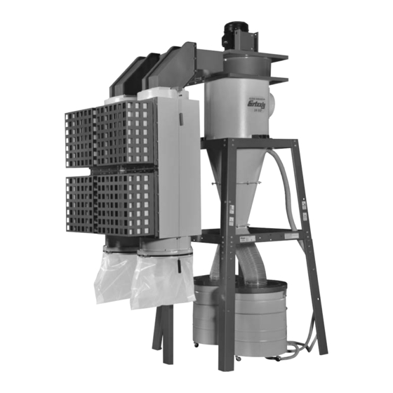
MODEL G0637HEP
7
⁄
HP DUAL-FILTRATION HEPA
1
2
CYCLONE DUST COLLECTOR
MANUAL INSERT
(For owner's manual revised August, 2017)
The Model G0637HEP is the same machine as the Model G0637 except for the dual-filtration HEPA filter
system and the collector mounting brackets. Except for the differences noted in this insert, all other content
in the Model G0637 owner's manual applies to this machine.
: To reduce the risk of serious injury, you MUST read and understand this insert—and
the entire Model G0637 manual—BEFORE assembling, installing, or operating this machine!
If you have any further questions about this manual insert or the differences between the Model G0637HEP
and the Model G0637, contact our Technical Support at (570) 546-9663 or email techsupport@grizzly.com.
COPYRIGHT © JANUARY, 2015 BY GRIZZLY INDUSTRIAL, INC. REVISED NOVEMBER, 2017 (AB)
WARNING: NO PORTION OF THIS MANUAL MAY BE REPRODUCED IN ANY SHAPE
OR FORM WITHOUT THE WRITTEN APPROVAL OF GRIZZLY INDUSTRIAL, INC.
(FOR MODELS MANUFACTURED SINCE 01/15) #BB17217 PRINTED IN TAIWAN
V1.11.17
Advertisement
Table of Contents

Related Manuals for Grizzly G0637HEP


Summary of Contents for Grizzly G0637HEP
- Page 1 (For owner's manual revised August, 2017) The Model G0637HEP is the same machine as the Model G0637 except for the dual-filtration HEPA filter system and the collector mounting brackets. Except for the differences noted in this insert, all other content in the Model G0637 owner's manual applies to this machine.
- Page 2 MACHINE DATA SHEET Customer Service #: (570) 546-9663 · To Order Call: (800) 523-4777 · Fax #: (800) 438-5901 MODEL G0637HEP 7‐1/2 HP 3‐PHASE DUAL‐FILTRATION HEPA CYCLONE DUST COLLECTOR Product Dimensions: Weight................................939 lbs. Width (side-to-side) x Depth (front-to-back) x Height............96-1/4 x 52-1/2 x 139-1/2 in.
- Page 3 Sound Rating ............................. 78 – 80 dB ISO 9001 Factory ..............................Yes Certified by a Nationally Recognized Testing Laboratory (NRTL) ................. Yes Model G0637HEP (Mfd. Since 01/15) The information contained herein is deemed accurate as of 11/23/2017 and represents our most recent product specifications. Model G0637HEP PAGE 2 OF 3 Due to our ongoing improvement efforts, this information may not accurately describe items previously purchased.
- Page 4 After all the parts have been removed from the Figure 2. Model G0637HEP inventory I–N. boxes, you should have the following items: O. Blower Housing with Motor ......1 Inventory: (Figures 1–5)
- Page 5 AJ. Collection Drum Vacuum Rings ....2 AK. Cyclone Vacuum Port ........ 1 AL. Vacuum Hose Clips ........2 Figure 4. Model G0637HEP Inventory X–Z. AA. Gaskets (not shown): — Intake Cylinder 3 x 6 x 1800mm .... 1 — Outlet Port 3 x 6 x 1100 ......1 —...
- Page 6 (see Figure 1). Install Adjustable Foot Here Outlet Gasket Brackets Provided Figure 9. Assembled HEPA support leg (comprised of three parts). Figure 7. Dust collector assembled with provided brackets and outlet gasket. Model G0442HEP/G0601HEP (Mfd. Since 01/15) Model G0637HEP (Mfd. Since 01/15)
- Page 7 " x 1" hex bolts, (16) ⁄ " flat washers, and (8) ⁄ " nuts. Rubber Gasket Filter Adapter Filter Assembly Figure 14. G0637HEP filter system completely installed. Figure 12. Attaching filter assembly to outlet. Model G0637HEP (Mfd. Since 01/15)
- Page 8 Main G0637HEP 440V 119-1 119-2 119-5 119-3 119-6 119-4 G0637HEP 220V 230-5 230-6 230-1 229-1 230-2 230-3 230-4 232A Model G0442HEP/G0601HEP (Mfd. Since 01/15) Model G0637HEP (Mfd. Since 01/15)
- Page 9 119-3 P0637HEP119-3 CONTACTOR MSN35-18D P0637HEP065 RUBBER GASKET 9" 119-4 P0637HEP119-4 OL RELAY NHD NTH-15 10–15A P0637HEP066 FUNNEL PORT 119-5 P0637HEP119-5 CIRCUIT BOARD W/TRANSFORMER P0637HEP067 HEX BOLT 5/16-18 X 1-1/4 119-6 P0637HEP119-6 MOTOR CORD 12G 4W 600V Model G0637HEP (Mfd. Since 01/15)
- Page 10 HEX BOLT 3/8-16 X 1 P0637HEP231 HEPA FILTER BODY (LEFT) P0637HEP202 TAP SCEW M4 X 12 232A P0637HEP232A HEPA FILTER KIT P0637HEP203 PHLP HD SCR 1/4-20 X 3/4 P0637HEP270 COLLECTOR MOUNTING BRACKET -10- Model G0442HEP/G0601HEP (Mfd. Since 01/15) Model G0637HEP (Mfd. Since 01/15)
- Page 11 ELECTRICITY LABEL P0637HEP131 CONTROL PANEL LABEL P0637HEP124 DISCONNECT POWER LABEL P0637HEP132 REMOTE CONTROL LABEL P0637HEP125 READ MANUAL LABEL P0637HEP133 GRIZZLY GREEN TOUCH-UP PAINT P0637HEP126 HANDS/OUTLET LABEL P0637HEP134 GRIZZLY PUTTY TOUCH-UP PAINT P0637HEP127 GLASSES/RESPIRATOR DC LABEL -11- Model G0637HEP (Mfd. Since 01/15)
- Page 13 (For models manufactured since 04/12) Model G0637 Model G0638 COPYRIGHT © MARCH, 2007 BY GRIZZLY INDUSTRIAL, INC., REVISED JANUARY, 2018 (JH) WARNING: NO PORTION OF THIS MANUAL MAY BE REPRODUCED IN ANY SHAPE OR FORM WITHOUT THE WRITTEN APPROVAL OF GRIZZLY INDUSTRIAL, INC.
- Page 14 This manual provides critical safety instructions on the proper setup, operation, maintenance, and service of this machine/tool. Save this document, refer to it often, and use it to instruct other operators. Failure to read, understand and follow the instructions in this manual may result in fire or serious personal injury—including amputation, electrocution, or death.
-
Page 15: Table Of Contents
Table of Contents INTRODUCTION ..........2 Decide Who Will Design ......37 Manual Accuracy ........... 2 Sketch Your Shop Layout ......37 Contact Info............ 2 Sketch a Basic Duct Layout ...... 37 Machine Description ........2 Determine Required CFMs ......38 Identification ........... -
Page 16: Introduction
Any updates to your model of spun-bond polyester. With the use of the of machine will be reflected in these documents cable and pulley system on the outside of the as soon as they are complete. -
Page 17: Identification
Identification Blower Housing Motor Noise Muffler Inlet Port Canister Filter Brush Handle Cyclone Funnel Canister Filter Assembly Junction Box Control Box Collection Drum w/Coaster Vacuum Hoses Figure 1. Identification (Model G0637 shown). To reduce your risk of serious injury, read this entire manual BEFORE... -
Page 18: Glossary Of Terms
Glossary Of Terms The following is a list of common definitions, terms and phrases that relate to dust collection and dust col- lectors in general. To get the most out of this manual, familiarize yourself with these terms before reading. Air Suction Capacity: The maximum volume Duct Grounding: A method of using bare wire of air (rated in CFM) that a dust collector can... -
Page 19: G0637 Machine Data Sheet
G0637 Machine Data Sheet MACHINE DATA SHEET Customer Service #: (570) 546-9663 · To Order Call: (800) 523-4777 · Fax #: (800) 438-5901 MODEL G0637 7‐1/2 HP 3‐PHASE CYCLONE DUST COLLECTOR Product Dimensions: Weight................................818 lbs. Width (side-to-side) x Depth (front-to-back) x Height............. 76-3/4 x 60 x 139-3/8 in. Footprint (Length x Width).......................... - Page 20 Main Specifications: Operation Dust Collector Type......................Two-Stage (Cyclone) Approved Dust Types..........................Wood Filter Type..........................Pleated Cartridge Airflow Capacity......................3468 CFM @ 4.3 in. SP Max Static Pressure (at 0 CFM)......................14.73 in. Main Inlet Size............................10 in. Inlet Adapter Included............................ No Machine Collection Capacity At One Time.......................
-
Page 21: G0638 Machine Data Sheet
G0638 Machine Data Sheet MACHINE DATA SHEET Customer Service #: (570) 546-9663 · To Order Call: (800) 523-4777 · Fax #: (800) 438-5901 MODEL G0638 10 HP 3‐PHASE CYCLONE DUST COLLECTOR Product Dimensions: Weight................................732 lbs. Width (side-to-side) x Depth (front-to-back) x Height............. 76-3/4 x 60 x 139-3/8 in. Footprint (Length x Width).......................... - Page 22 Main Specifications: Operation Dust Collector Type......................Two-Stage (Cyclone) Approved Dust Types..........................Wood Filter Type..........................Pleated Cartridge Airflow Capacity......................4029 CFM @ 4.3 in. SP Max Static Pressure (at 0 CFM)......................16.8 in. Main Inlet Size............................12 in. Inlet Adapter Included............................ No Machine Collection Capacity At One Time.......................
-
Page 23: Section 1: Safety
SECTION 1: SAFETY For Your Own Safety, Read Instruction Manual Before Operating This Machine The purpose of safety symbols is to attract your attention to possible hazardous conditions. This manual uses a series of symbols and signal words intended to convey the level of impor- tance of the safety messages. - Page 24 INTENdEd usAGE. Only use machine for its machine in good working condition. A machine intendedpurposeandnevermakemodifications that is improperly maintained could malfunction, not approved by Grizzly. Modifying machine or leadingtoseriouspersonalinjuryordeath. using it differently than intended may result in ChECK dAMAGEd PARTs. Regularly inspect...
-
Page 25: Additional Safety For Dust Collectors
Additional Safety for Dust Collectors INTENDED USE. This dust collector is only SUSPENDED DUST PARTICLES AND IGNITION SOURCES. DO NOT operate the dust collector in intended for collecting wood dust and chips from woodworking machines. DO NOT use this dust areas were explosion risks are high. -
Page 26: Section 2: Power Supply
SECTION 2: POWER SUPPLY Availability Circuit Information Before installing the machine, consider the avail- A power supply circuit includes all electrical ability and proximity of the required power supply equipment between the breaker box or fuse panel circuit. If an existing circuit does not meet the in the building and the machine. -
Page 27: Connection Type
Connection Type Extension Cords A permanently connected (hardwired) power sup- Since this machine must be permanently con- ply is typically installed with wires running through nected to the power supply, an extension cord mounted and secured conduit. A disconnecting cannot be used. means, such as a locking switch (see following Figure), must be provided to allow the machine Phase Converter... -
Page 28: Model G0637 440V Conversion
All wiring changes must be inspected by a quali- fied electrician before the machine is connected to the power source. If you need help at any time during this procedure, call Grizzly Tech Support at (570) 546-9663. To rewire the Model G0637 for 440V operation:... -
Page 29: Model G0638 440V Conversion
Model G0638 440V Conversion Remove the motor cords from the two mag- netic switch assemblies in the control box To operate the Model G0638 on 440V power, you (see Figure 6) and install the new motor must purchase a G0638 440V Conversion Kit. cords. -
Page 30: Correcting Phase Polarity
Correcting Phase Polarity Secure the control box cover, then re-connect the machine to power. This subsection is only provided for troubleshoot- ing. If you discover during the test run that the Perform Step 10 of the test run on Page 34 machine will not operate, or that the impeller spins to confirm that the power connections are backward, the power connections may be wired... -
Page 31: Section 3: Setup
Remove the packaging materials ects. Regardless of the content in this sec- from around your machine and inspect it. If you tion, Grizzly Industrial will not be held liable discover any damage, please call us immediately for accidents caused by lack of training. -
Page 32: Inventory
Inventory Inventory Intake Cylinder ........... 1 K. Outlet Port ..........1 L. Cyclone Funnel (Large) ......1 M. Intake Barrel ..........1 The following is a list of items shipped with your N. Cyclone Funnel (Small) ......1 machine. Before beginning setup, lay these items O. - Page 33 AJ. Hardware (not shown): Flexible Ducts 9" x 25 ⁄ " ......2 Z. Noise Mufflers ..........2 —Hex Bolts ⁄ "-16 x 1 ⁄ " ......8 AA. Canister Filters —Hex Bolts ⁄ "-18 x ⁄ " ......30 —Model G0637 510 x 1200mm ....
-
Page 34: Site Considerations
Site Considerations Weight Load Physical Environment Refer to the Machine Data Sheet for the weight The physical environment where the machine is of your machine. Make sure that the surface upon operated is important for safe operation and lon- which the machine is placed will bear the weight gevity of machine components. -
Page 35: Mounting To Shop Floor
Mounting to Shop Floor Assembly Mounting to Shop Floor To assemble the dust collector: Since your dust collector will be hardwired to the Use (8) ⁄ "-16 x ⁄ " hex bolts, (16) ⁄ " flat power source, we strongly recommend secur- washers, and (8) ⁄... - Page 36 Use (16) ⁄ "-16 x ⁄ " hex bolts, (32) ⁄ " flat washer, and (16) ⁄ "-16 lock nuts to con- nect the two sides of the upper stand with When using power lifting equipment dur- two upper stand braces and two lower stand ing the assembly, make sure the equipment braces—only finger tighten the fasteners is safe, fully operational, and adequately...
- Page 37 Note: Because this part of the dust collector Barrel is not accessible after assembly, consider using Medium Strength Blue Thread Locker (Grizzly Model T21854) on the bolts that Mounting Holes secure the intake cylinder to the motor/blower housing assembly to ensure that the fasten- ers won't come loose with vibration.
- Page 38 13. Install the four cyclone mounting brackets Note: Orient the two assemblies so that the with (8) ⁄ "-16 x 1 ⁄ " hex bolts, (16) ⁄ " large, round intake port of the intake barrel flat washers, and (8) ⁄...
- Page 39 18. Apply the 3 x 6 x 300mm foam tape to the 22. Slide the four lower stand legs onto the bot- mating surface of the cyclone vacuum port, toms of the upper stand legs—do NOT install then attach it to the cyclone funnel with (4) the fasteners yet.
- Page 40 28. Apply the 3 x 6 x 1100mm gasket to the 33. Attach the two long brace supports to the square side of the outlet port. filter braces with (4) ⁄ "-16 x ⁄ " hex bolts, (8) ⁄ " flat washers, and (4) ⁄...
- Page 41 35. Attach the 3 x 15 x 700mm gaskets to the 39. Apply the 3 x 6 x 2200mm gasket to the larg- upper rim of the canister filter assembly and er, top end of the small cyclone funnel, then both rims of the noise muffler.
- Page 42 43. For each lower collection drum cylinders, 45. Install the rubber seal over the top lip of the attach the casters to the bottom using (4) ⁄ "- collection drum rim. Pay special attention 16 hex nuts, (4) ⁄ " flat washers, and (4) ⁄...
- Page 43 48. Place the collection drum vacuum rings on 50. Connect the dust collection drum assemblies the bottom of the collection drums (see to the funnel port with the 9" flexible ducts Figure 42). and 9" duct clamps (see Figure 44). Note: During operation, this ring and the vacuum connection to the cyclone funnel will prevent the collection bag from collapsing.
- Page 44 52. Connect the vacuum hoses between the 54. Model G0637 only: Mount the control box vacuum manifold and the collection drum onto the lower stand brace with (3) ⁄ "-16 x vacuum ports with (4) 1 ⁄ " hose clamps (see ⁄...
-
Page 45: Power Connection
Power Connection 56. Open the control box and identify the four mounting holes in the back of the cabinet. 57. Attach the control box to the bracket already Due to the complexity required for planning, mounted on the stand brace with (4) M6-1 x bending, and installing the conduit necessary 15 Phillips head screws, (4) 6mm flat wash- for a code-compliant hardwire setup, an electri-... -
Page 46: G0637 Power Connection
G0637 Power Connection G0638 Power Connection The incoming power wires must be connected to The incoming power wires must be connected to round the three terminals on the master power switch the three terminals on the overload relay marked 3-PHASE marked 1L/1, 3L/2, and 5L/3, and the incoming 1L/1, 3L/2, and 5L/3, and the incoming ground 220 VAC... -
Page 47: Test Run
Test Run Press the ON/OFF button to turn the machine ON. Make sure your hand stays poised over the switch in case you need to quickly turn the machine OFF. When the assembly is complete, test run your dust collection system to make sure it operates Listen to and watch for abnormal noises or properly. - Page 48 10. Safely use a ladder so that you can observe 11. For the G0638 only: the motor fan through the top motor cover. Stay clear of the motor, then use the remote a. Turn the machine OFF. control to turn the motor ON and OFF while you note the fan rotation direction.
-
Page 49: Section 4: Designing The System
Model G0637/G0638 allows great flexibility than metal. in planning and designing of your dust collection duct layout. Grizzly offers a complete line of dust collection accessories for setting up a stationary system. Additionally, Grizzly offers a complete guide book titled Dust Collection Basics. -
Page 50: Metal Duct
However, the cost of specifically Another disadvantage is the rough internal seams designed flexible duct can vary greatly. Grizzly and crimped ends that unavoidably increase static offers polyethylene hose, which is well suited for pressure loss. -
Page 51: System Design
Line Duct Our Workshop Planner will allow you to quickly and easily design and print a basic shop layout. Don't worry, non-Grizzly brand machines can be Figure 61. Efficient duct layout. substituted with Grizzly machines for layout pur- poses. Note: After you're finished, make sure to save your layout for later modification. -
Page 52: Determine Required Cfms
Directional changes should be kept to a mini- If the machine does not have a built-in dust port, mum. The more directional change fittings use the following table to determine which size of you use directly increases the overall resis- dust port to install. -
Page 53: Determining Main Line Duct Size
Determining Main Line Duct Size Jointer Sander Planer/ The general rule of thumb for a main line duct is Moulder that the velocity of the airflow must not fall below 4" 4" 6" 3500 FPM. For small/medium sized shops, using the inlet size 5"... -
Page 54: Planning Drop Downs
Planning Drop Downs Duct Approximate Approximate Dia. Static Pressure Static Pressure Plan the drop downs for each machine, using Loss Per Foot of Loss Per Foot blast gates wherever possible to control airflow. Rigid Pipe of Flex Pipe Main Branch Main Branch Lines... - Page 55 STATIC PRESSURE (Inch/H2O) Elbows/Branches 6" 45˚ Y-Branch ........ 0.329 Figure 73. CFM for static pressure loss of line 2 HP GRIZZLY DUST COLLECTOR PERFORMANCE RESULTS 4" 45˚ Elbow ........0.225 connected to a dust collector & router. Max CFM Max SP...
-
Page 56: Example Materials List
1600 1460 1200 Description Model Quantity STATIC PRESSURE (Inch/H2O) 6" Rigid Pipe at 20' G7364 2 HP GRIZZLY DUST COLLECTOR PERFORMANCE RESULTS 4" Rigid Pipe at 10' G6162 Max CFM Max SP Volts Inlet Impeller 3468 14.7 7.5HP... -
Page 57: System Grounding
System Grounding Be sure that you extend the bare copper wire down all branches of the system. Do not forget to connect the wires to each other with wire nuts when two branches meet at a “Y” or “T” connec- Since plastic hose is abundant, relatively inex- tion. -
Page 58: Section 5: Accessories
Accessories SECTION 5: ACCESSORIES H5293—4" Metal Duct Starter Kit G6162—4" x 5' Straight Metal Pipe H5295—5" Metal Duct Starter Kit G7346—5" x 5' Straight Metal Pipe H5297—6" Metal Duct Starter Kit G7364—6" x 5' Straight Metal Pipe Save over 20% with this great starter kit. H5227—7"... - Page 59 We carry many different branches, all from 4"–8" with 90˚, 60˚, 45˚, or 30˚ curves. designed to minimize airflow resistance. Also, available with a 90˚ long radius curve. Call (800) 523-4777 or visit www.grizzly. com for more information and pricing. 90° 90° Long Radius Figure 85.
-
Page 60: Section 6: Operations
Damage to your eyes, lungs, and ears could ning any projects. Regardless of the con- result from using this machine without tent in this section, Grizzly Industrial will proper protective gear. Always wear safety not be held liable for accidents caused by glasses, a respirator, and hearing protection lack of training. -
Page 61: Section 7: Maintenance
SECTION 7: MAINTENANCE Cleaning Filters Always disconnect power to the machine before The Model G0637/G0638 dust collector has a performing maintenance. gentle brush system inside the canisters for Failure to do this may removing any built-up dust from the filter pleats. result in serious person- al injury. -
Page 62: Rinsing Filter
Remove the six hex bolts, hex nuts, and flat ings beginning on Page 60 to order the correct washers from the rim of the canister base, as filter from Grizzly at (800) 523-4777. shown in Figure 90. Tools Needed Open-End Wrench 10mm ........1 Wrench or Socket 12mm ........ - Page 63 With help from another person to steady the Before re-inserting a filter into the assembly, canister assembly, turn it upside down and make sure that the filter brush base is aligned remove the two M8-1.25 x 20mm hex bolts, with two of the fastener holes around the base of the assembly (see Figure 93).
-
Page 64: Section 8: Service
Troubleshooting SECTION 8: SERVICE Review the troubleshooting and procedures in this section if a problem develops with your machine. If you need replacement parts or additional help with a procedure, call our Technical Support at (570) 546-9663. Note: Please gather the serial number and manufacture date of your machine before calling. Troubleshooting Motor &... -
Page 65: Dust Collector Operation
Dust Collector Operation Symptom Possible Cause Possible Solution Loud, repetitious 1. Dust collector is not on a flat surface and 1. Stabilize the dust collector. noise, or excessive wobbles. vibration coming 2. Impeller is damaged and unbalanced. 2. Disconnect dust collector from power, and inspect from dust collector. -
Page 66: Section 9: Wiring
Technical source. Support at (570) 546-9663. The photos and diagrams included in this section are best viewed in color. You can view these pages in color at www.grizzly.com. -52- Model G0637/G0638 (Mfd. Since 04/12) -
Page 67: G0637 Electrical Components
G0637 electrical components G0637 Electrical Components Figure 94. Model G0637 control box. Figure 95. Model G0637 motor wiring (220V). Figure 96. Model G0637 junction box wiring. READ ELECTRICAL SAFETY -53- Model G0637/G0638 (Mfg. Since 04/12) ON PAGE 52! -
Page 68: G0637 Control Box Wiring Diagram
G0637 control box wiring G0637 Control Box Wiring Diagram G0637 Control Box 220 VAC Wiring Diagram If connecting machine to a phase converter, the manufactured leg Ground must be connected to terminal 3L/2. 3-PHASE 220 VAC DISCONNECT SWITCH If motor rotates in opposite direc- (as recommended ) tion, swap any two power source wires at the incoming terminals. -
Page 69: G0637 440V Wiring Diagram
G0637 440V Wiring Diagram Ground 3-PHASE 440 VAC DISCONNECT SWITCH (as recommended ) 440V Magnetic Contactor Switch and Overload Relay OL_NO 13NO NHD C-18D Circuit Board 14NO 30VA Transformer ON/OFF NTH-15 Switch 440V Motor Figure 97. G0637 440V control box wiring. READ ELECTRICAL SAFETY -55- Model G0637/G0638 (Mfg. -
Page 70: G0637 Motor Wiring Diagram
G0637 Motor Wiring Diagram G0637 motor wiring G0637 Motor Wiring Diagram (220V/440V) 220 VAC, 3-Phase Control Box (Pages 53 & 54) 220VAC (Pre-Wired) 440 VAC, 3-Phase (12G 600V Cord) 440VAC (Optional) When rewiring to 440V, you must purchase and install the 440V Conversion Kit. Refer to Page 145 for details. -
Page 71: G0638 Electrical Components
G0638 electrical components G0638 Electrical Components Figure 98. Model G0638 control box. Figure 100. Model G0638 motor wiring (220V). Figure 99. Model G0638 control box cover (shown from back). READ ELECTRICAL SAFETY -57- Model G0637/G0638 (Mfg. Since 04/12) ON PAGE 52! -
Page 72: G0638 Control Box Wiring Diagram
G0638 Control Box Wiring Diagram G0638 control wiring G0638 Control Box 220 VAC Wiring Diagram If connecting machine to a phase converter, the manufactured leg must be connected to terminal 3L/2. If motor rotates in opposite direc- tion, swap any two power source wires at the incoming terminals. -
Page 73: G0638 Motor Wiring Diagram
G0638 Motor Wiring Diagram G0638 motor wiring G0638 Motor Wiring Diagram (220V/440V) Control Box (Pages 57 & 58) 220V, 3-Phase (12G 300V) 220V, 3-Phase 220VAC (Pre-Wired) (12G 300V) When rewiring to 440V, you must 440V, 3-Phase (12G 600V) purchase and install the 440V Conversion Kit. -
Page 74: Section 10: Parts
Parts SECTION 10: PARTS Parts Breakdown G0638 440V G0637 440V 119V2-1 119V2-1 119V2-2 119V2-5 119V2-2 119V2-3 G0637 220V 119V2-6 3V2-1 3V2-2 119V2-4 3V2-5 112V2 3V2-3 41AV3 158 159 3V2-4 119V2 G0638 220V 3V2-3 3V2-5 3V2-4 3V2-1 3V2-8 3V2-7 41-5V2 3V2-6 3V2-9 52V2 3V2-2... - Page 75 G0637 Only Parts List PART # DESCRIPTION PART # DESCRIPTION P0637001 MOTOR 7-1/2HP 220/440V 3-PH 41AV3 P0637041AV3 CANISTER ASSEMBLY, BEIGE V3.07.12 P0637001-1 MOTOR JUNCTION BOX 41V2 P0637041V2 CANISTER FILTER 486 X 1195MM V2.11.09 P0637001-2 MOTOR JUNCTION BLOCK 41-4V3 P0637041-4V3 CANISTER CAGE ASSY, BEIGE V3.07.12 P0637001-3 MOTOR FAN COVER 112V2...
- Page 76 G0637/G0638 Common Parts List PART # DESCRIPTION PART # DESCRIPTION P0637028 LEFT FILTER L-BRACE P0637084 PHLP HD SCR 10-24 X 3/8 P0637029 SHORT FILTER BRACE SUPPORT P0637085 HEX NUT 10-24 P0637030 HEX BOLT 3/8-16 X 3/4 P0637086 PHLP HD SCR 10-24 X 3/8 P0637031 HEX NUT 3/8-16 P0637087...
- Page 77 Safety labels help reduce the risk of serious injury caused by machine hazards. If any label comes off or becomes unreadable, the owner of this machine MUST replace it in the original location before resuming operations. For replacements, contact (800) 523-4777 or www.grizzly.com. -63-...
- Page 78 Would you recommend Grizzly Industrial to a friend? _____ Yes _____No Would you allow us to use your name as a reference for Grizzly customers in your area? Note: We never use names more than 3 times. _____ Yes _____No 10.
- Page 79 FOLD ALONG DOTTED LINE Place Stamp Here GRIZZLY INDUSTRIAL, INC. P.O. BOX 2069 BELLINGHAM, WA 98227-2069 FOLD ALONG DOTTED LINE Send a Grizzly Catalog to a friend: Name_______________________________ Street_______________________________ City______________State______Zip______ TAPE ALONG EDGES--PLEASE DO NOT STAPLE...
-
Page 80: Warranty And Returns
WARRANTY AND RETURNS Grizzly Industrial, Inc. warrants every product it sells for a period of 1 year to the original purchaser from the date of purchase. This warranty does not apply to defects due directly or indirectly to misuse, abuse, negligence, accidents, repairs or alterations or lack of maintenance.
Need help?
Do you have a question about the G0637HEP and is the answer not in the manual?
Questions and answers