Table of Contents
Advertisement
Quick Links
model g0703/g0703p 1
⁄
hp
1
2
cyclone dust collector
oWner's manual
(For models manufactured since 03/12)
Model
Model
g0703
g0703p
Copyright © AUgUSt, 2009 By grizzly indUStriAl, inC. rEViSEd April, 2012 (Kn)
Warning: no portion of this manual may be reproduced in any shape
or form Without the Written approval of grizzly industrial, inc.
#trCrBltSJB11940 printEd in tAiWAn
Advertisement
Table of Contents

Related Manuals for Grizzly g0703


Summary of Contents for Grizzly g0703
- Page 1 Model g0703 g0703p Copyright © AUgUSt, 2009 By grizzly indUStriAl, inC. rEViSEd April, 2012 (Kn) Warning: no portion of this manual may be reproduced in any shape or form Without the Written approval of grizzly industrial, inc. #trCrBltSJB11940 printEd in tAiWAn...
- Page 2 This manual provides critical safety instructions on the proper setup, operation, maintenance, and service of this machine/tool. Save this document, refer to it often, and use it to instruct other operators. Failure to read, understand and follow the instructions in this manual may result in fire or serious personal injury—including amputation, electrocution, or death.
-
Page 3: Table Of Contents
table of contents introduction ..........2 section 5: operations ......33 Manual Accuracy ........... 2 general operation ........33 Contact info............ 2 remote Control operation ......34 Machine description ........2 reprogramming receiver ......34 identification ........... 3 operating remote receiver ...... 35 glossary of terms ......... -
Page 4: Introduction
Any updates to your model of machine will be reflected in these documents Built for convenience, a remote control allows as soon as they are complete. -
Page 5: Identification
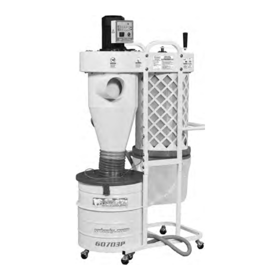
identification remote relay Switch Filter Brush handle Motor Blower housing inlet restrictor inlet note: The inlet restrictor is only installed if dust collector is to be used on a Canister Filter 20 Amp-110 Volt circuit and circuit breaker tripping occurs during start-up. Collection Bag Cyclone Funnel Stand... -
Page 6: Glossary Of Terms
Glossary Of Terms The following is a list of common definitions, terms and phrases that relate to dust collection and dust col- lectors in general. To get the most out of this manual, familiarize yourself with these terms before reading. Air Suction Capacity: The maximum volume Duct Grounding: A method of using bare wire of air (rated in CFM) that a dust collector can... -
Page 7: Machine Data Sheet
machine data sheet MACHINE DATA SHEET Customer Service #: (570) 546-9663 · To Order Call: (800) 523-4777 · Fax #: (800) 438-5901 MODEL G0703P 1-1/2 HP CYCLONE DUST COLLECTOR - models g0703/g0703p POLAR BEAR SERIES® 1-1/2 hp cyclone dust collector Product Dimensions: Weight................................ - Page 8 Bag Information No of Lower Bags............................. 1 Lower Bag Capacity........................... 2.66 cu. ft. Lower Bag Diameter..........................15-3/4 in. Lower Bag Length..........................23-5/8 in. Canister Information No of Canister Filters............................1 Canister Filter Diameter........................15-3/4 in. Canister Filter Length..........................21 in. Filter Surface Area..........................
-
Page 9: Section 1: Safety
section 1: safety For Your Own Safety, Read Instruction Manual Before Operating this Machine The purpose of safety symbols is to attract your attention to possible hazardous conditions. This manual uses a series of symbols and signal words intended to convey the level of impor- tance of the safety messages. - Page 10 DISCONNECTING POWER SUPPLY.Alwaysdis- GUARDS & COVERS. Guards and covers can connect machine from power supply before ser- protect you from accidental contact with moving vicing, adjusting, or changing cutting tools (bits, parts or flying debris. Make sure they are prop- blades,...
-
Page 11: Additional Safety For Dust Collectors
additional safety for dust collectors intended use. this dust collector is only suspended dust particles and ignition sources. do not operate the dust collector in intended for collecting wood dust and chips from woodworking machines. do not use this dust areas were explosion risks are high. -
Page 12: Section 2: Power Supply
section 2: poWer supply availability circuit information Before installing the machine, consider the avail- A power supply circuit includes all electrical ability and proximity of the required power supply equipment between the breaker box or fuse panel circuit. If an existing circuit does not meet the in the building and the machine. -
Page 13: Circuit Requirements For 220V
circuit requirements for 220v For 220V operation: The plug specified under “Circuit Requirements for 220V” on the previous This machine can be converted to operate on a page has a grounding prong that must be attached 220V power supply. The intended 220V circuit to the equipment-grounding wire on the included must have a verified ground and meet the require- power cord. -
Page 14: Extension Cords
220V plug, re-wiring the motor, and installing a wire to a live (current carrying) terminal. 220V circuit board. The 220V circuit board, Part # P0703P088, can be purchased by calling Grizzly Check with a qualified electrician or service per- Customer Service at (800) 523-4777. - Page 15 MOTOR 110V remove the wire nuts indicated in figure 6. remove the wires connected to the circuit Start Capacitor Capacitor 300MFD 40MFD board, as indicated in figure 8. 125VAC 250VAC Circuit Start Board 220V Capacitor Capacitor 300MFD 40MFD 125VAC 250VAC Circuit remove remove...
-
Page 16: Section 3: Setup
section 3: setup needed for setup this machine presents serious injury hazards the following items are needed to complete the to untrained users. read setup process, but are not included with your through this entire manu- machine: al to become familiar with the controls and opera- description tions before starting the... -
Page 17: Hardware Recognition Chart
hardware recognition chart -15- Model g0703/g0703p (Mfg. Since 3/12) -
Page 18: Inventory
inventory general inventory (figure 11): Upper rails ..........2 pull handle ..........1 K. Spring Clamp ..........1 the inventory and assembly for the g0703 and l. rubber Seal 1.6 M ........1 the g0703p are identical. After all the parts have m. -
Page 19: Site Considerations
site considerations Weight Load Physical Environment Refer to the Machine Data Sheet for the weight The physical environment where the machine is of your machine. Make sure that the surface upon operated is important for safe operation and lon- which the machine is placed will bear the weight gevity of machine components. -
Page 20: Assembly
assembly position the stand over the dust collector housing, as shown in figure 15, and install ⁄ "-18 x 1 ⁄ " hex bolt and flat washer on each side of the stand to serve as pivot bolts to assemble the dust collector: (leave bolts loose for now). - Page 21 install the handle with (4) ⁄ "-18 x ⁄ " hex 10. Attach the casters to the bottom of the drum bolts and (4) ⁄ " washers, as shown in using (4) ⁄ "-16 nuts, (4) ⁄ " flat washers, and figure 17.
- Page 22 12. place the drum extender onto the drum, see 14. place the dust collection bag seat into the figure 21. duct collection drum, as shown in figure 23. drum Extender drum Clamp drum figure 23. installing the dust collection bag seat. figure 21.
- Page 23 16. install the dust collection bag into the collec- 18. Connect the 1" hose and the 7" hose to the tion drum as shown in figure 25. collection drum. 19. Connect the other end of both hoses to the cyclone housing (see figure 27), and secure them in place with the appropriate diameter hose clamps.
-
Page 24: Power Connection
power connection disconnecting power 1. Turn the machine power switch OFF. 2. Grasp the molded plug and pull it completely After you have completed all previous setup out of the receptacle. Do not pull by the cord instructions and circuit requirements, the machine as this may damage the wires inside. is ready to be connected to the power supply. To avoid unexpected startups or property dam- age, use the following steps whenever connecting or disconnecting the machine. -
Page 25: Test Run
test run toggle the power switch (see figure 30) to on (|). the power indicator light will illumi- nate. When the assembly is complete, test run your dust collection system to make sure it operates ir Sensor properly. power Switch on/off NOTICE Button... -
Page 26: Section 4: Designing The System
section 4: designing the system duct material general You have many choices regarding main line and the Model g0703/g0703p is designed to col- branch line duct material. For best results, use lect dust from one machine at a time. this can metal duct for the main line and branch lines, then be accomplished by either connecting it to one use short lengths of flexible hose to connect each... -
Page 27: Metal Duct
However, the cost of specifically Another disadvantage is the rough internal seams designed flexible duct can vary greatly. Grizzly and crimped ends that unavoidably increase static offers polyethylene hose, which is well suited for pressure loss. -
Page 28: System Design
Line Duct our Workshop Planner will allow you to quickly and easily design and print a basic shop layout. don't worry, non-grizzly brand machines can be figure 35. Efficient duct layout. substituted with grizzly machines for layout pur- poses. note: After you're finished, make sure to save your layout for later modification. -
Page 29: Step 4. Determine Required Cfm Of Each Machine
directional changes should be kept to a mini- if the machine does not have a built-in dust port, mum. the more directional change fittings use the following table to determine which size of you use directly increases the overall resis- dust port to install. -
Page 30: Determining Main Line Duct Size
determining main line duct size Jointer Sander Planer/ The general rule of thumb for a main line duct is Moulder that the velocity of the airflow must not fall below 4" 4" 6" 3500 FPM. For small/medium sized shops, using the inlet size 5"... -
Page 31: Multiple Dust Ports
multiple dust ports duct approximate approximate dia. static pressure static pressure if your machine has multiple dust ports, add the loss per foot of loss per foot total CFM given for each dust port size from the rigid pipe of flex pipe table under step 4 (approximate required airflow) on the previous page. - Page 32 performance curve Add the additional factors from the following- Compare the total static pressure loss for that table to your list. line to the closest CFM given in figure 47. example: the g0703/g0703p performance additional factors static pressure curve is illustrated in figure 47. Find 4.8 on Seasoned (well used) the Static pressure axis (the amount of total 1"...
-
Page 33: Example Materials List
3) increasing machine needed. refer to accessories for dust collection dust port size, 4) moving machine closer to components available through grizzly.com. dust collector to eliminate duct length, and 5) reducing 90˚ elbows or replacing them description... -
Page 34: System Grounding
system grounding Be sure that you extend the bare copper wire down all branches of the system. do not forget to connect the wires to each other with wire nuts when two branches meet at a “y” or “t” connec- Since plastic hose is abundant, relatively inex- tion. -
Page 35: Section 5: Operations
Fine training before beginning any projects. dust regardless of the content in this section, grizzly industrial will not be held liable for Wood accidents caused by lack of training. Chips figure 50. Model g0703 flow. -
Page 36: Remote Control Operation
remote control to prevent accidental startups by other common rF items like garage door openers, the remote operation control signal for the Model g0703/g0703p is ir (infrared) rather than a rF (radio frequency) sig- nal. the remote control switch features a factory- set 256-code channel setting, which prevents the A remote control receiver and handheld control- simultaneous startup of two g0703p's. -
Page 37: Operating Remote Receiver
replacing canister operating remote receiver refer to figure 52 and the following descriptions filter to understand the receiver control functions. For a more thorough cleaning every few months (under heavy use), remove the filter from the dust collector and rinse it with warm water. Allow the filter to air dry only. - Page 38 remove the twelve hex nuts from the blower Carefully lift the filter out of the canister housing base, as shown in figure 54. assembly, as shown in figure 55. figure 54. removing hex bolts from canister figure 55. removing filter. assembly.
-
Page 39: Section 6: Accessories
NOTICE refer to the newest copy of the grizzly catalog for other accessories available for this machine. figure 57. dust collection pipe clamps. - Page 40 t23415—clear flexible hose 4" x 10' g2752—4" rolling floor sweep t23425—black flexible hose 4" x 10' g2753—4" bench attachment g3179—heavy-duty clear flex hose 4" x 10' g2754—4" floor attachment g8830—hose hanger 4 ⁄ " these attachments are indispensable for collect- g1552—y-fitting 4"...
-
Page 41: Section 7: Maintenance
section 7: maintenance cleaning filter always disconnect power to the machine before the Model g0703/g0703p dust collector has a performing maintenance. crank handle (see figure 63) driven filter flap failure to do this may system for removing any built-up dust from the result in serious person- filter pleats. -
Page 42: Section 8: Service
section 8: service review the troubleshooting and procedures in this section to fix or adjust your machine if a problem devel- ops. if you need replacement parts or you are unsure of your repair skills, then feel free to call our technical Support at (570) 546-9663. -
Page 43: Dust Collector Operation
dust collector operation Symptom possible Cause possible Solution loud, 1. dust collector is not on a flat surface and 1. Stabilize the dust collector. repetitious wobbles. noise, or 2. impeller is damaged and unbalanced. 2. disconnect dust collector from power, and inspect excessive the impeller for dents, bends, loose fins. -
Page 44: Section 9: Wiring
Technical source. Support at (570) 546-9663. The photos and diagrams included in this section are best viewed in color. You can view these pages in color at www.grizzly.com. -42- Model g0703/g0703p (Mfg. Since 3/12) -
Page 45: Electrical Component Locations
electrical component locations remote receiver figure 64. G0703/G0703P electrical component locations. figure 65. G0703/G0703P remote receiver circuit and components. -43- Model g0703/g0703p (Mfg. Since 3/12) -
Page 46: G0703/G0703P 110V Wiring Diagram
g0703/g0703p 110v Wiring diagram Motor 110V Start Capacitor Capacitor 300MFD 40MFD 125VAC 250VAC Circuit Board 110V Circuit Breaker/ Thermal Overload Power Switch Ground Neutral Neutral 110 VAC 110 VAC Ground L5-30 Plug 5-20 Plug (As Recommended, (As Recommended, With Inlet Restrictor) Without Inlet Restrictor) -44- Model g0703/g0703p (Mfg. -
Page 47: G0703/G0703P 220V Wiring Diagram
g0703/g0703p 220v Wiring diagram Motor 220V Start Capacitor Capacitor 300MFD 40MFD 125VAC 250VAC Circuit Board 220V Circuit Breaker/ Thermal Overload Power Switch Ground 6-15 Plug (As Recommended) -45- Model g0703/g0703p (Mfg. Since 3/12) -
Page 48: Section 10: Parts
SECTION 10: PARTS G0703 Breakdown 1V2-21 1V2-17 1V2-18 1V2-15 1V2-6 1V2-3 1V2-1 1V2-20 1V2-7 220V Conversion Kit 1V2-8 1V2-2 88V2 1V2-10 1V2-9 1V2-4 1V2-11 1V2-5 1V2-12 1V2-14 1V2-24 1V2-23 1V2-25 1V2-22 10-1 53 54 13-1 58-1 13V2 22-1 58-1 66V2 98-1 98-1 86-1... -
Page 49: G0703 Parts List
G0703 Parts List PART # DESCRIPTION PART # DESCRIPTION P0703001V2 MOTOR 1-1/2 HP 110/220V 1PH V2.01.12 P0703037 LOWER COLLECTION DRUM 1V2-1 P0703001V2-1 MOTOR FAN COVER P0703038 DRUM SUCTION PIPE 1V2-2 P0703001V2-2 MOTOR FAN 38-1 P0703038-1 DRUM SUCTION PIPE SEAL 1V2-3 P0703001V2-3 REMOTE RECEIVER BOX P0440056... -
Page 50: G0703P Breakdown
G0703P Breakdown 1-21 1-17 1-18 1-15 220V Conversion Kit 1-20 1-10 1-11 1-24 1-12 1-14 1-25 1-23 1-22 10-1 53 54 13-1 58-1 22-1 58-1 98-1 98-1 86-1 38-1 -48- Model G0703/G0703P (Mfg. Since 3/12) -
Page 51: G0703P Parts List
G0703P Parts List REF PART # DESCRIPTION REF PART # DESCRIPTION P0703P001 MOTOR 1-1/2 HP 110/220V 1PH V1 P0703036 VACUUM SUCTION PLATE P0703P001-1 MOTOR FAN COVER P0703P037 LOWER COLLECTION DRUM P0703P001-2 MOTOR FAN P0703038 DRUM SUCTION PIPE P0703P001-3 REMOTE RECEIVER BOX 38-1 P0703038-1 DRUM SUCTION PIPE SEAL... -
Page 52: G0703/G0703P Labels
Safety labels help reduce the risk of serious injury caused by machine hazards. If any label comes off or becomes unreadable, the owner of this machine MUST replace it in the original location before resuming operations. For replacements, contact (800) 523-4777 or www.grizzly.com. -50-... -
Page 53: Warranty Card
Would you recommend Grizzly Industrial to a friend? _____ Yes _____No Would you allow us to use your name as a reference for Grizzly customers in your area? Note: We never use names more than 3 times. _____ Yes _____No 10. - Page 54 FOLD ALONG DOTTED LINE Place Stamp Here GRIZZLY INDUSTRIAL, INC. P.O. BOX 2069 BELLINGHAM, WA 98227-2069 FOLD ALONG DOTTED LINE Send a Grizzly Catalog to a friend: Name_______________________________ Street_______________________________ City______________State______Zip______ TAPE ALONG EDGES--PLEASE DO NOT STAPLE...
-
Page 55: Warranty & Returns
Warranty & returns Grizzly Industrial, Inc. warrants every product it sells for a period of 1 year to the original purchaser from the date of purchase. This warranty does not apply to defects due directly or indirectly to misuse, abuse, negligence, accidents, repairs or alterations or lack of maintenance. - Page 56 Buy Direct and Save with Grizzly – Trusted, Proven and a Great Value! ® ~Since 1983~ Visit Our Website Today For Current Specials! ORDER 24 HOURS A DAY! 1-800-523-4777...
Need help?
Do you have a question about the g0703 and is the answer not in the manual?
Questions and answers