Advertisement
Safety Instructions
The intended use of this product is to provide a connection from the SMC wireless communication system to pneumatic devices.
These safety instructions are intended to prevent hazardous situations and/or equipment damage. These instructions indicate the level of potential hazard with the labels of "Caution," "Warning" or "Danger." They are all important notes for safety and must be followed in addition to International Standards (ISO/IEC) *1), and other safety regulations.
*1) ISO 4414: Pneumatic fluid power - General rules relating to systems.
ISO 4413: Hydraulic fluid power - General rules relating to systems.
IEC 60204-1: Safety of machinery - Electrical equipment of machines.
(Part 1: General requirements)
ISO 10218-1: Manipulating industrial robots -Safety. etc.
- Refer to product catalogue, Operation Manual and Handling Precautions for SMC Products for additional information.
- Keep this manual in a safe place for future reference.

Caution indicates a hazard with a low level of risk which, if not avoided, could result in minor or moderate injury.

Warning indicates a hazard with a medium level of risk which, if not avoided, could result in death or serious injury.

Danger indicates a hazard with a high level of risk which, if not avoided, will result in death or serious injury.
- Always ensure compliance with relevant safety laws and standards.
All work must be carried out in a safe manner by a qualified person in compliance with applicable national regulations.
Specifications
General specifications
| Item | Specification |
| Enclosure rating | IP20 |
| Ambient operating temperature | -10 to +50°C |
| Ambient storage temperature | -20 to +60°C |
| Ambient humidity | 35 to 85% RH (no condensation) |
| Withstand voltage | 500 VAC for 1 minute between external terminals (including the FE terminal) and enclosure screws |
| Insulation resistance | 10 MΩ or more (500 VDC between external terminals (including the FE terminal) and enclosure screws |
| Vibration resistance | EN61131-2 compliant: 5 ≤ f < 8.4 Hz 3.5 mm 8.4 ≤ f < 150 Hz 9.8 m/s2 |
| Impact resistance | EN61131-2 compliant: 147 m/s2, 11 ms |
| Weight | 130 g |
Electrical specifications – EXW1-RDX# Input unit
| Item | Specification | |
| US1 (for control / input) power supply voltage | 24 VDC ±10% | |
| Current consumption | 100 mA or less | |
| Inputs | Number of points | 16 points (2 points / connector) |
| Input type | NPN | |
| Connector type | e-CON (4 pins) | |
| Max. supply current for sensor | 0.3 A / connector, 2 A/unit | |
| ON current | 0.5 mA Typ. | |
| OFF current | 2 mA or less | |
| ON voltage | 11 V or more | |
| OFF current | 5 V or less | |
| Short circuit protection | Included | |
Electrical specifications – EXW1-RDY# Output unit
| Item | Specification | |
| US1 (for control / input) power supply voltage | 24 VDC ±10% | |
| US2 (for output) power voltage | 24 VDC ±10% | |
| Current consumption (US1) | 100 mA or less | |
| Outputs | Number of points | 16 points (2 points / connector) |
| Output type | NPN | |
| Connector type | e-CON (4 pins) | |
| Maximum load current | 0.3 A / point, 2 A / unit | |
| Short circuit protection | Included | |
Electrical specifications – EXW1-RDM# Input / Output unit
| Item | EXW1-RDMP# | EXW1-RDMN# | |
| US1 (for control / input) power voltage drop | 24 VDC ±10% | ||
| US2 (for output) power voltage) | 24 VDC ±10% | ||
| Current consumption (US1) | 100 mA or less | ||
| Inputs | Number of points | 8 points (2 points / connector) | |
| Input type | PNP | NPN | |
| Connector type | e-CON (4 pins) | ||
| Max. supply current for sensor | 0.3 A / connector, 1 A / unit | ||
| ON current | 0.5 mA Typ. | ||
| OFF current | 2 mA or less | ||
| ON voltage | 11 V or more | ||
| OFF current | 5 V or less | ||
| Short circuit protection | Included | ||
| Outputs | Number of points | 8 points (2 points / connector) | |
| Output type | PNP | NPN | |
| Connector type | e-CON (4 pins) | ||
| Maximum load current | 0.3 A / point, 2 A / unit | ||
| Short circuit protection | Included | ||
Wireless Communication specifications
| Item | Specifications |
| Protocol | SMC original protocol (SMC encryption) |
| Radio wave type (spread) | Frequency Hopping Spread Spectrum (FHSS) |
| Frequency band | 2.4 GHz (2403 to 2481 MHz) |
| Frequency channel select function (F.C.S.) | Supported *1 |
| Frequency channels | 79 ch max. (Bandwidth: 1.0 MHz) |
| Communication speed | 1 Mbps / 250 kbps *2 |
| Communication distance | Up to 100 m line of sight (depending on the environment) |
| Radio Law certificates | Refer to the operation manual on the SMC website |
*1: The number of selectable frequency channels varies depending on the product number.
*2: Select a protocol before performing pairing (V.2.0: 1 Mbps, V.1.0: 250 kbps). Different communication speeds are mutually incompatible.
NFC Communication specifications
| Item | Specifications |
| Communication standard | ISO / IEC14443B (Type-B) |
| Frequency | 13.56 MHz |
| Communication speed | 20 to 100 kHz (I2C) |
| Communication distance | Up to 1 cm |
* NFC component is a 13.56 MHz passive-type RFID tag.
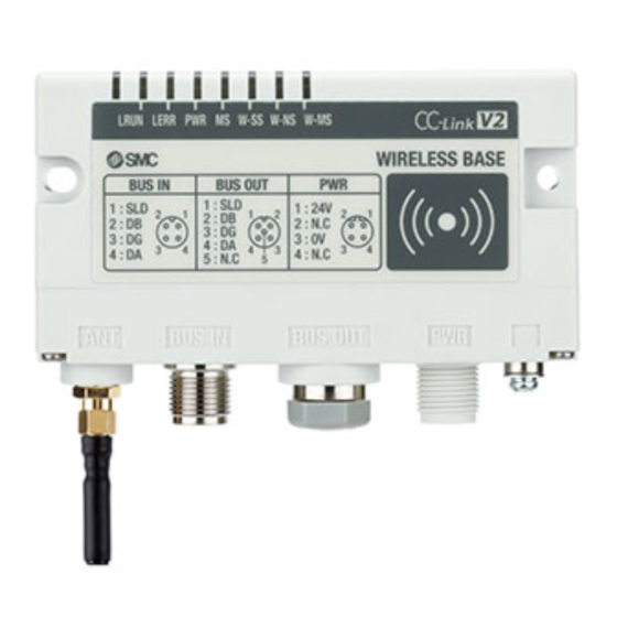
Name and Function of parts
- Compact Remote Input unit (EXW1-RDX#)
")
- Compact Remote Output unit (EXW1-RDY#)
")
- Compact Remote Input / Output unit (EXW1-RDM#)
")
")
")
")
| No. | Item | Description |
| 1 | Mounting holes | Mounting holes for compact wireless base (2 x M4). |
| 2 | PWR (Power connector) | Supplies power to the compact wireless Remote. |
| 3 | RF connector | SMA coaxial connector for external antenna (external antenna versions only). |
| 4 | Fn (Pairing button) | Press the button to select pairing mode. |
| 5 | NFC antenna area | Area in close contact with the NFC reader / writer ("○" marks the centre). |
| 6 | LED display | Indicates the status of the compact wireless Remote. |
| 7 | FE terminal and mounting hole (M4) | To be connected to Ground (for improved noise immunity). |
| 8 | Connector for Inputs | Connector for an input device. (PIN2, PIN4: input). |
| 9 | Connector for Outputs | Connector for an output device. (PIN2, PIN4: output). |
- Ground connection
The Ground connection to the FE terminal (M4 mounting hole) should be as close as possible to the product and the grounding wire should be as short as possible.
Installation
Do not install the product unless the safety instructions have been read and understood.
Mounting
Mount the unit with M4 screws (not supplied) using the 2 mounting holes in the unit (Recommended torque: 0.8 ±10% N•m).

Environment
- Do not use in an environment where corrosive gases, chemicals, salt water or steam are present.
- Do not use in an explosive atmosphere.
- Do not expose to direct sunlight. Use a suitable protective cover.
- Do not install in a location subject to vibration or impact in excess of the product's specifications.
- Do not mount in a location exposed to radiant heat that would result in temperatures in excess of the product's specifications.
Wiring
Wiring Connections – EXW1-RDX# Input unit
- Power supply connector
![]()
- INPUT connector
![]()


Wiring Connections – EXW1-RDY# Output unit
- Power supply connector
![]()
- OUTPUT connector
![]()
* +COM is connected to 24V (US2) inside the product.


Wiring Connections – EXW1-RDM# Input / Output unit
- Power supply connector
![]()
- INPUT connector
![]()
- OUTPUT connector (PNP outputs)
![]()
- OUTPUT connector (NPN outputs)
![]()
* -COM is connected to 0V (US2) and +COM to 24V (US2) inside the product.


Settings
- Flow chart for using the wireless system.
To use SMC wireless units (Base and Remotes), they need to be set up using an NFC reader/writer and the I/O Configurator. A setup procedure using NFC is shown below.
Refer to the operation manual for each manufacturer for how to set the controller and the PLC.
- Step 1. Preparation before use (PC, Application)
- Install the NFC reader / writer and drivers.
- Install the I/O Configurator
-
Step 2. Setting / installation of the wireless unit
-
Parameter setting of the Remote (optional).
-
Communication, system and frequency channel select function (F.C.S.) settings of the Base.
-
Register the Remote to the Base (pairing)
-
Installation and wiring.
-
- Step 3. Connection to PLC
Note) Refer to the operation manual of the PLC manufacturer for connection to a PLC and Configurator.
LED Display
- The LED indicators on the compact wireless Remote indicate the power supply, communication and diagnostic status. The same LED indications are used for all of the EXW1-RD# series.


| LED | LED Colour | Operation |
| PWR | Green LED ON | US1 (for control) power supply is ON |
| Red LED flashing | US2 (for output) power supply voltage level is abnormal (when the setting is enabled) | |
| OFF | US1 (for control) power supply is OFF | |
| MS | Green LED ON | Compact wireless Base is operating normally |
| Red LED flashing | Recoverable error is detected. (LED flashes when more than one diagnostic information item is detected).
| |
| Red LED ON | Unrecoverable error is detected. | |
| OFF | US1 (for control) power supply is OFF. | |
| W-SS | Green LED ON | Received radio wave intensity level 3. |
| Green LED flashing (1 Hz) | Received radio wave intensity level 2. | |
| Green LED flashing (2 Hz) | Received radio wave intensity level 1. | |
| Red LED flashing | Protocol V.1.0 wireless communication is not established. | |
| Orange LED flashing | Protocol V.2.0 wireless communication is not established. | |
| OFF | Wireless Base is not registered. | |
| W-NS | Green LED ON | Wireless Base connected correctly. |
| Red LED flashing | Base not connected. | |
| Orange LED flashing | Pairing operation is in progress. | |
| Red LED ON | Base not connected (Unrecoverable error in wireless communication). | |
| Red / Green LED flashing | Wireless communication connection is being configured (Pairing). | |
| OFF | Base not registered. US1 (for control / input) power supply is OFF. |
Refer to the Operation manual on the SMC website (URL: https://www.smcworld.com) for further LED Display details.
How to Order
Refer to the Operation manual or catalogue on the SMC website (URL: https://www.smcworld.com) for How to Order information.
Outline Dimensions (mm)
Refer to the Operation manual or catalogue on the SMC website (URL: https://www.smcworld.com) for Outline dimensions.
Maintenance
General Maintenance
- Not following proper maintenance procedures could cause the product to malfunction and lead to equipment damage.
- If handled improperly, compressed air can be dangerous.
- Maintenance of pneumatic systems should be performed only by qualified personnel.
- Before performing maintenance, turn off the power supply and be sure to cut off the supply pressure. Confirm that the air is released to atmosphere.
- After installation and maintenance, apply operating pressure and power to the equipment and perform appropriate functional and leakage tests to make sure the equipment is installed correctly.
- If any electrical connections are disturbed during maintenance, ensure they are reconnected correctly and safety checks are carried out as required to ensure continued compliance with applicable national regulations.
- Do not make any modification to the product.
- Do not disassemble the product, unless required by installation or maintenance instructions.
Limitations of Use
Limited warranty and Disclaimer/Compliance Requirements
Refer to Handling Precautions for SMC Products.
NOTE
This equipment has been tested and found to comply with the limits for a Class A digital device, pursuant to Part 15 of the FCC Rules.
These limits are designed to provide reasonable protection against harmful interference when the equipment is operated in a commercial environment.
This equipment generates, uses, and can radiate radio frequency energy and, if not installed and used in accordance with the instruction manual, may cause harmful interference to radio communications.
Operation of this equipment in a residential area is likely to cause harmful
interference in which case the user will be required to correct the interference at his own expense.
- Influence of radio frequency on implantable medical devices:
The radio frequency generated by this product may give an adverse effect on implantable medical devices, such as implantable cardiac pacemakers and implantable cardioverter defibrillators. Please read catalogues or instruction manuals of the equipment and device which may be affected by radio frequencies for any instructions for use or contact their manufacturers.
Product Disposal
This product shall not be disposed of as municipal waste. Check your local regulations and guidelines to dispose of this product correctly, in order to reduce the impact on human health and the environment.
Contacts
Refer to www.smcworld.com or www.smc.eu for your local distributor / importer.
SMC Corporation
URL: https://www.smcworld.com (Global)
https://www.smceu.com (Europe)
SMC Corporation, 4-14-1, Sotokanda, Chiyoda-ku, Tokyo 101-0021, Japan
Specifications are subject to change without prior notice from the manufacturer.
© 2021 SMC Corporation
All Rights Reserved.

Documents / Resources
References
Download manual
Here you can download full pdf version of manual, it may contain additional safety instructions, warranty information, FCC rules, etc.
Advertisement


Need help?
Do you have a question about the EXW1-RDX# Series and is the answer not in the manual?
Questions and answers