
Related Manuals for TP-Link TL-SG3109


Summary of Contents for TP-Link TL-SG3109
- Page 1 TP-LINK TECHNOLOGIES CO., LTD. E-mail: support@tp-link.com Website: http://www.tp-link.com Add: 3/F., Building R1-B, Hi-tech Industrial Park, Shennan Rd., Shenzhen, P.R.China...
-
Page 2: Installation Guide
TL-SG3109 9-port Gigabit Managed Switch TL-SL3428 24+4G Gigabit Managed Switch TL-SL3452 48+4G Gigabit Managed Switch Installation Guide... -
Page 3: Fcc Statement
COPYRIGHT & TRADEMARKS Specifications are subject to change without notice. registered trademark of TP-LINK Technologies Co., Ltd. Other brands and product names are trademarks or registered trademarks of their respective holders. No part of the specifications may be reproduced in any form or by any means or used to make any derivative such as translation, transformation, or adaptation without permission from TP-LINK Technologies Co., Ltd. -
Page 4: Safety Notices
which the receiver is connected. Consult the dealer or an experienced radio/TV technician for help. This device complies with Part 15 of the FCC Rules. Operation is subject to the following two conditions: 1) This device may not cause harmful interference. 2) This device must accept any interference received, including interference that may cause undesired operation. -
Page 5: Table Of Contents
1.1 Intended Audience ...2 1.2 Agreement ...2 1.3 Guide Overview ...2 Section 2. Device Description ...3 2.1 Features...3 2.2 TP-Link TL-SG3109 Description ...4 2.3 TP-Link TL-SL3428 Description ...6 2.4 TP-Link TL-SL3452 Description ...8 2.5 Back Panel ...10 2.6 Device Hardware Interfaces ...10 2.6.1 RJ-45 Base-T Fast Ethernet Ports ...10... - Page 6 3.2.1 Desktop or Shelf Installation ...18 3.2.2 Rack Installation ...18 3.3 Connecting the Device ...20 3.3.1 Connecting the Switch to a Terminal ...20 3.3.2 AC Power Connection ...21 Section 4. Starting and Configuring the Device ...22 4.1 Configuring the Terminal ...22 4.2 Installation Procedure ...23...
- Page 7 4.5.3.3 Configuring an Initial Telnet Password ...38 4.5.3.4 Configuring an Initial SSH password ...38 4.5.3.5 Configuring an Initial HTTP Password ...39 4.5.3.6 Configuring an initial HTTPS Password ...39 4.6 Startup Procedures ...39 4.6.1 Software Download [Option 1] ...41 4.6.1.1 Software Download through TFTP Server ...42 4.6.2 Erasing the Flash File [Option 2] ...46 4.6.3 Password Recovery [Option 3] ...46 4.6.4 Enter Diagnostic Mode [Option4] ...47...
-
Page 8: Package Contents
CD Two mounting brackets and other fittings Note: If any of the listed contents are damaged or missing, please contact the retailer from whom you purchased the TL-SG3109/TL-SL3428/TL-SL3452 Gigabit Managed Switch for assistance. Gigabit Managed Switch Family Installation Guide... -
Page 9: Section 1: Introduction
This guide is intended for network administrators familiar with IT concepts and network terminology. 1.2 Agreement Due to the similarity in function of the TL-SG3109/TL-SL3428/TL-SL3452 Gigabit Managed Switch Family, this installation guide will illustrate the general usage of this switch family. The “switch” referred in this guide indicates the TL- SG3109/TL-SL3428/TL-SL3452 Gigabit Managed Switch Family. -
Page 10: Section 2. Device Description
There are a range of devices which offer variable solutions for specific requirements. The offering includes the following devices: 10/100/1000 devices (GE devices) TP-Link TL-SG3109 — 8 10/100/1000Base-TX ports and 1 SFP 10/100 devices (FE devices) TP-Link TL-SL3428 — 24 10/100Base-TX ports and 4 Giga ports(2 x ... -
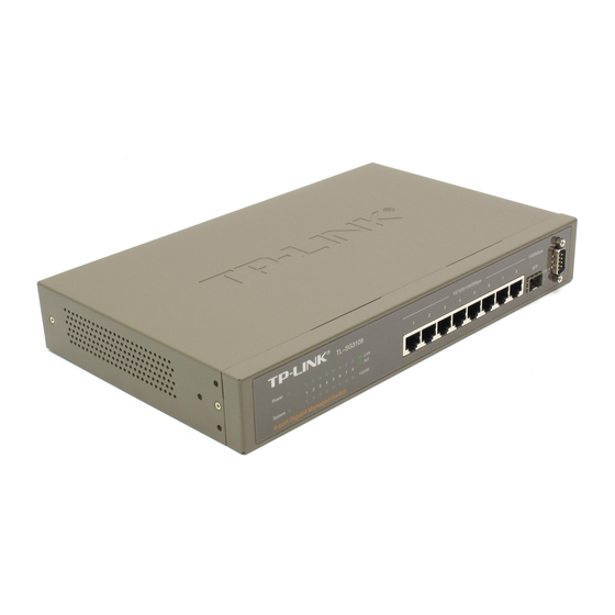
Page 11: Tp-Link Tl-Sg3109 Description
Support DNS, RADIUS, TACACS+, multilingual, logging file, SNTP, SNMP v1, v2 and v3 Support manual port control Support Virtual Cable Test (VCT) diagnostics 2.2 TP-Link TL-SG3109 Description The following figure illustrates the TL-SG3109 front panel. Gigabit Managed Switch Family Installation Guide... - Page 12 Power System 9-port Gigabit Managed Switch Figure 2-1: TL-SG3109 Front Panel The TL-SG3109 device front panel is configured as follows: 8 1000Base-T Copper port — Copper RJ-45 Gigabit port designated on the device as ports 1-8. 1 1000Base-FX SFP port — Fiber Gigabit ports designated on the device ...
-
Page 13: Tp-Link Tl-Sl3428 Description
LEDs Bottom LED SFP Link/ SFP Port ACT LED Power System LEDs System Table 1: TL-SG3109 Port LED Indications 2.3 TP-Link TL-SL3428 Description The following figure illustrates the TL-SL3428 front panel. TL-SL3428 24+4G Gigabit Managed Power Link 11 13 21 23... - Page 14 TL-SG3109/TL-SL3428/TL-SL3452 2 1000Base-T Copper port — Copper RJ-45 Gigabit port designated on the device as ports GIGA1 and GIGA2. 2 1000Base-FX SFP port — Fiber Gigabit ports designated on the device as ports SFP1 and SFP2. RS-232 DB-9 Console port — An asynchronous serial console port ...
-
Page 15: Tp-Link Tl-Sl3452 Description
• Solid Green — A valid link is established on the port. • Flashing Green — Packet transmission or reception is occurring on the port. • Solid Red — Power is supplied to the switch and is operating normally. • Off — Power is disconnected. - Page 16 TL-SG3109/TL-SL3428/TL-SL3452 numbers. 2 1000Base-T Copper port — Copper RJ-45 Gigabit port designated on the device as ports GIGA1 and GIGA2. 2 1000Base-FX SFP port — Fiber Gigabit ports designated on the device as ports SFP1 and SFP2. RS-232 DB-9 Console port — An asynchronous serial console port ...
-
Page 17: Back Panel
• Solid Green — A valid link is established on the port. • Flashing Green — Packet transmission or reception is occurring on the port. • Solid Red — Power is supplied to the switch and is operating normally. • Off — Power is disconnected. -
Page 18: Sfp Port
Determines whether the link to the attached device requires a “normal” connection (such as when connecting the port to a PC) or an “uplink” connection (such as when connecting the port to a router, switch, or hub). Configures the RJ-45 port to enable communications with the attached ... -
Page 19: Rs-232 Db-9 Console Port
TL-SG3109/TL-SL3428/TL-SL3452 2.6.3 RS-232 DB-9 Console Port The DB-9 port is an asynchronous serial console port supporting the RS-232 electrical specification. The port is used to connect the device to a console managing the device. This interface configuration is as follows: Eight data bits. - Page 20 TL-SG3109/TL-SL3428/TL-SL3452 The following shows the way to make the cable use to connect switch to network adapter, and cable use to connect switch to switch/hub/bridge. Pin signal allocation for RJ-45 connector MDI-II TX+ (send) TX- (send) RX+ (receive) No use...
-
Page 21: Sfp Connector
MDI-X 2.7.2 SFP Connector The following figure illustrates an SFP connector which is entered into the device SFP port. 2.8 Physical Dimensions The TL-SG3109 device has the following physical dimensions: Width: 294mm (11.57 inch) Depth: 180mm (7.09 inch) ... -
Page 22: Section 3. Mounting Device
Section 3. Mounting Device 3.1 Preparing for Installation 3.1.1 Installation Precautions Warnings The surface on which the switch is placed should be adequately secured to prevent it from becoming unstable and/or falling over. Ensure the power source circuits are properly grounded. -
Page 23: Site Requirements
TL-SG3109/TL-SL3428/TL-SL3452 Cautions Ensure the air flow around the front, sides, and back of the switch is not restricted. Ensure the cooling vents are not blocked. Do not install the switch in an environment where the operating ambient ... -
Page 24: Unpacking Essentials
TL-SG3109/TL-SL3428/TL-SL3452 Console cable with DB-9 connector This "Installation Guide", the "Embedded Web System User Guide" and documentation CD Two mounting brackets and other fittings 3.1.3.2 Unpacking Essentials Note Before unpacking the device, inspect the package and report any evidence of damage immediately. -
Page 25: Desktop Or Shelf Installation
TL-SG3109/TL-SL3428/TL-SL3452 3.2.1 Desktop or Shelf Installation When installing the switch on a desktop or shelf, the rubber feet included with the device should first be attached. Attach these cushioning feet on the bottom at each corner of the device. Ensure the surface is be able to support the weight of the device and the device cables. - Page 26 TL-SG3109/TL-SL3428/TL-SL3452 on the rack mounting bracket. The following figure illustrates where to mount the brackets. Pow er 24 +4 G Gi ga bi t M an ag ed Sw itc h 11 13 15 17 Lin k 21 23 100 Mb ps...
-
Page 27: Connecting The Device
TL-SG3109/TL-SL3428/TL-SL3452 5. Secure the unit to the rack with the rack screws (not provided). Fasten the lower pair of screws before the upper pair of screws. This ensures that the weight of the unit is evenly distributed during installation. Ensure that the ventilation holes are not obstructed. -
Page 28: Ac Power Connection
TL-SG3109/TL-SL3428/TL-SL3452 setting is for Terminal keys (not Windows keys). Note When using HyperTerminal with Microsoft have Windows 2000 Service Pack 2 or later installed. With Windows Service Pack 2, the arrow keys function properly in HyperTerminal’s VT100 emulation. Go to www.microsoft.com for information on Windows 2000 service packs. -
Page 29: Section 4. Starting And Configuring The Device
Ensure that the terminal emulation software is configured as follows: 1. Connect the Chassis serial port to the switch module. The baud rate automatically boots up at 38400. 2. Set the data format to 8 data bits, 1 stop bit, and no parity. -
Page 30: Installation Procedure
Gigabit Managed Switch Family Installation Guide TL-SG3109/TL-SL3428/TL-SL3452 ® Windows 2000 Service Pack 2 or later is installed. With Windows 2000 Service Pack 2, the arrow keys function properly in HyperTerminal’s VT100 emulation. Go to www.microsoft.com for information on Windows 2000 service packs. -
Page 31: Device Port Default Settings
TL-SG3109/TL-SL3428/TL-SL3452 4.2.1 Device Port Default Settings The following table describes the device port default settings. Function Port speed and mode Port forwarding state Head of line blocking prevention Flow Control Back Pressure Note These default settings can be modified once the device is installed. - Page 32 TL-SG3109/TL-SL3428/TL-SL3452 the device is fully operational before completely booting. If a critical problem is detected, the program flow stops. If POST passes successfully, a valid executable image is loaded into RAM. POST messages are displayed on the terminal and indicate test success or failure.
-
Page 33: Configuration Overview
TL-SG3109/TL-SL3428/TL-SL3452 indicates that no problems were encountered during boot. During boot, the Startup menu can be used to run special procedures. To enter the Startup menu, press <Esc> or <Enter> within the first two seconds after the auto-boot message is displayed. -
Page 34: Initial Configuration
TL-SG3109/TL-SL3428/TL-SL3452 Note After making any configuration changes, the new configuration must be saved before rebooting. To save the configuration, enter: console# copy running-config startup-config 4.4.1 Initial Configuration Initial configuration, which starts after the device has booted successfully, includes static IP address and subnet mask configuration, and setting user name and privilege level to allow remote management. -
Page 35: Static Ip Address And Subnet Mask
IP address by entering the show ip interface command. The commands to configure the device are port specific. To manage the switch from a remote network, a static route must be configured, which is an IP address to where packets are sent when no entries are found in the device tables. -
Page 36: Assigning Static Ip Addresses On A Default Vlan
TL-SG3109/TL-SL3428/TL-SL3452 gateway is defined as 100.1.1.10. Note that by default, all ports are members of VLAN 1, which is the default VLAN. console# configure console(config)# interface vlan 1 console(config-if)# ip address 100.1.1.1 255.255.255.0 console(config-if)# exit console# ip default-gateway 100.1.1.10 Confirm that the IP address has been correctly configured as follows:... -
Page 37: User Name
TL-SG3109/TL-SL3428/TL-SL3452 Verifying the IP and Default Gateway Addresses Ensure that the IP address and the default gateway were properly assigned by executing the following command and examining its output: Gateway IP Address ---------------------------------------------------------- ---- 192.168.1.1 IP address ------------------- 192.168.1.123/24 4.4.1.3 User Name A user name is used to manage the device remotely, for example through SSH, Telnet, or the Web interface. -
Page 38: Snmp Community Strings
MIBs information before being able to manage the MIBs. All parameters are manageable from any SNMP management platform, except the SNMP management station IP address and community (community name and access rights). The SNMP management access to the switch is disabled if no community strings exist. Note The device switch is delivered with no community strings configured. - Page 39 Common practice is to use two community strings for the switch one (public community) with read-only access and the other (private community) with read-write access.
-
Page 40: Advanced Configuration
TL-SG3109/TL-SL3428/TL-SL3452 To configure SNMP station IP address and community string(s) perform the following: 1. At the console prompt, enter the command Enable. The prompt is displayed as 2. Enter the command configure and press <Enter>. 3. In the configuration mode, enter the SNMP configuration command with... -
Page 41: Receiving An Ip Address From A Dhcp Server
TL-SG3109/TL-SL3428/TL-SL3452 accounting (AAA) mechanism, and includes the following topics: Receiving an IP Address from a DHCP Server Receiving an IP Address from a BOOTP Server Security Management and Password Configuration When configuring or receiving IP addresses through DHCP and BOOTP, the configuration received from these servers includes the IP address, and may include a subnet mask and default gateway. -
Page 42: Receiving An Ip Address From A Bootp Server
DHCP on an interface that connects to the same DHCP server, or to one with an identical configuration.As a result of the copying configuration, the switch retrieves the new configuration file and boots from it. The device then enables DHCP as instructed in the new configuration file, and the DHCP instructs it to reload the same file. -
Page 43: Security Management And Password Configuration
TL-SG3109/TL-SL3428/TL-SL3452 Note When the device reboot begins, any input at the ASCII terminal or keyboard automatically cancels the BOOTP process before completion, and the device does not receive an IP address from the BOOTP server. The following example illustrates the process: console>... -
Page 44: Configuring Security Passwords Introduction
TL-SG3109/TL-SL3428/TL-SL3452 4.5.3.1 Configuring Security Passwords Introduction The security passwords can be configured for the following services: Console Telnet HTTP HTTPS Note Passwords are user-defined. When creating a user name, the default priority is "1," which allows ... -
Page 45: Configuring An Initial Telnet Password
TL-SG3109/TL-SL3428/TL-SL3452 When changing a device mode to enable, enter george at the password prompt. 4.5.3.3 Configuring an Initial Telnet Password To configure an initial Telnet password, enter the following commands: console(config)# aaa authentication login default line console(config)# aaa authentication enable default line... -
Page 46: Configuring An Initial Http Password
TL-SG3109/TL-SL3428/TL-SL3452 4.5.3.5 Configuring an Initial HTTP Password To configure an initial HTTP password, enter the following commands: console(config)# ip http authentication local console(config)# username admin password user1 level 15 4.5.3.6 Configuring an initial HTTPS Password To configure an initial HTTPS password, enter the following commands:... - Page 47 TL-SG3109/TL-SL3428/TL-SL3452 The procedures called from the Startup menu cover software download, flash handling, and password recovery. The diagnostics procedures are for use by technical support personnel only and are not disclosed in this document. The Startup menu can be entered when booting the device. A user input must be entered immediately after the POST test.
-
Page 48: Software Download [Option 1]
TL-SG3109/TL-SL3428/TL-SL3452 [1] Download Software [2] Erase Flash File [3] Password Recovery Procedure [4] Enter Diagnostic Mode [5] Set Terminal Baud-Rate [6] Back Enter your choice or press 'ESC' to exit: The Startup menu procedures can be performed using the ASCII terminal or Windows HyperTerminal. -
Page 49: Software Download Through Tftp Server
TL-SG3109/TL-SL3428/TL-SL3452 3. In the Filename field, enter the file path for the file to be downloaded. 4. Ensure that the Xmodem protocol is selected in the Protocol field. 5. Press Send. The software is downloaded. Note After software download, the device reboots automatically. - Page 50 TL-SG3109/TL-SL3428/TL-SL3452 2. Make sure that the file to be downloaded is saved on the TFTP server (the arc file). 3. Enter show version to verify which software version is currently running on the device. The following is an example of the information that appears: console# show version SW version 1.0.0.30 ( date 16-Jul-2006 time 09:19:44 )
- Page 51 TL-SG3109/TL-SL3428/TL-SL3452 indicate that the copying process failed. 6. Enter the reload command. The following message is displayed: console# reload This command will reset the whole system and disconnect your current session. Do you want to continue (Y/N) [N]? 7. Enter y . The device reboots.
- Page 52 TL-SG3109/TL-SL3428/TL-SL3452 console# copy tftp://176.215.31.3/332448-10018.rfb boot !!!!!!!!!!!!!!!!!!!!!!!!!!!!!!!!!!!!!!!!!!!!!!!!!!!!!!!!!!!!!!!!!!!!!!!!!!!!!!!!!!!!!!!!! !!!!!!!!!!!!!!!!!!!!!!!!!!!!!!!!!!!!!!!!!!! Copy: 2739187 bytes copied in 00:01:13 [hh:mm:ss] 5. Enter the reload command. The following message is displayed: console# reload This command will reset the whole system and disconnect your current session. Do you want to continue (Y/N) [N]? 6.
-
Page 53: Erasing The Flash File [Option 2]
TL-SG3109/TL-SL3428/TL-SL3452 The switch is ready to receive the file via the XModem protocol. 2. Specify the path of the source file to begin the transfer process. The following is an example of the information that appears: console# copy xmodem: image Please download program using XMODEM 4.6.2 Erasing the Flash File [Option 2]... -
Page 54: Enter Diagnostic Mode [Option4]
Gigabit Managed Switch Family Installation Guide TL-SG3109/TL-SL3428/TL-SL3452 If a password is lost, you can perform the password recovery procedure from the Startup menu. The password recovery procedure enables entry to the device one time without a password. To recover a lost password for the local terminal only: 1.