
Related Manuals for Supero SuperServer 6025B-8


Summary of Contents for Supero SuperServer 6025B-8
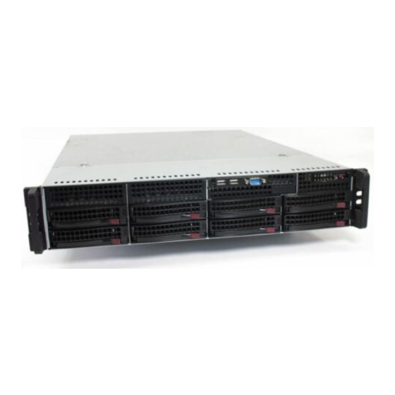
- Page 1 UPER ® 6025B-T UPER ERVER 6025B-8 UPER ERVER NIC 2 NIC 1 USER’S MANUAL 1.0b...
- Page 2 Please Note: For the most up-to-date version of this manual, please see our web site at www.supermicro.com. Super Micro Computer, Inc. ("Supermicro") reserves the right to make changes to the product described in this manual at any time and without notice. This product, including software, if any, and documentation may not, in whole or in part, be copied, photocopied, reproduced, translated or reduced to any medium or machine without prior written consent.
-
Page 3: Preface
Chapter 2: Server Installation This chapter describes the steps necessary to install the SuperServer 6025B- T/6025B-8 into a rack and check out the server confi guration prior to powering up the system. If your server was ordered without processor and memory com- ponents, this chapter will refer you to the appropriate sections of the manual for their installation. - Page 4 UPER ERVER 6025B-T/6025B-8 User's Manual Chapter 4: System Safety You should thoroughly familiarize yourself with this chapter for a general overview of safety precautions that should be followed when installing and servicing the SuperServer 6025B-T/6025B-8. Chapter 5: Advanced Serverboard Setup Chapter 5 provides detailed information on the X7DBE/X7DB8 serverboard, in- cluding the locations and functions of connections, headers and jumpers.
- Page 5 Preface Notes...
-
Page 6: Table Of Contents
UPER ERVER 6025B-T/6025B-8 User's Manual Table of Contents Preface About This Manual ... iii Manual Organization ... iii Chapter 1: Introduction Overview ... 1-1 Serverboard Features ... 1-2 Server Chassis Features ... 1-3 Contacting Supermicro ... 1-6 Chapter 2: Server Installation Overview ... - Page 7 Chapter 5: Advanced Serverboard Setup Handling the Serverboard ... 5-1 Processor and Heatsink Installation ... 5-2 Connecting Cables ... 5-5 Connecting Data Cables ... 5-5 Connecting Power Cables ... 5-5 Connecting the Control Panel ... 5-6 I/O Ports ... 5-7 Installing Memory ...
- Page 8 UPER ERVER 6025B-T/6025B-8 User's Manual SMB Power ... 5-17 SGPIO ... 5-18 JLAN1/2 ... 5-18 Alarm Reset ... 5-18 Keylock ... 5-18 Jumper Settings ... 5-19 Explanation of Jumpers ... 5-19 CMOS Clear ... 5-19 VGA Enable/Disable ... 5-19 3rd Power Supply Alarm Enable/Disable ... 5-20 Watch Dog Enable/Disable ...
- Page 9 Chapter 7: BIOS Introduction ... 7-1 Running Setup ... 7-2 Main BIOS Setup ... 7-2 Advanced Setup ... 7-7 Security ... 7-19 Boot ... 7-20 Exit ... 7-21 Appendices: Appendix A: BIOS POST Messages Appendix B: BIOS POST Codes Appendix C: Software Installation Appendix D: System Specifi...
- Page 10 UPER ERVER 6025B-T/6025B-8 User's Manual Notes...
-
Page 11: Chapter 1: Introduction
SC823TQ-550LP/SC823S-550LP 2U server chassis and the X7DBE/X7DB8 Intel Xeon serverboard. Please refer to our web site for information on operating systems that have been certifi ed for use with the 6025B-T/6025B-8. In addition to the serverboard and chassis, various hardware components have been... -
Page 12: Serverboard Features
ERVER 6025B-T/6025B-8 User's Manual Serverboard Features At the heart of the SuperServer 6025B-T/6025B-8 lies the X7DBE/X7DB8, a dual processor serverboard based on the Intel 5000P chipset and designed to provide maximum performance. Below are the main features of the X7DBE/X7DB8. (See Figure 1-1 for a block diagram of the Intel 5000P chipset). -
Page 13: Server Chassis Features
PCI Expansion Slots The X7DBE/X7DB8 has six PCI expansion slots, which includes two x8 PCI-Express slots, one x4 PCI-Express slot, two PCI-X 133 MHz slots and one PCI-X 100 MHz slot. On the X7DB8, the 100 MHz PCI-X slot supports Zero Channel RAID. Onboard Controllers/Ports One fl... - Page 14 Serial ATA drives. Front Control Panel The control panel on the SuperServer 6025B-T/6025B-8 provides system monitoring and control. LEDs indicate system power, HDD activity, network activity, system overheat and power supply failure. A main power button and a system reset button are also included.
- Page 15 Slot 4: PCI-Express x8 Slot 2: PCI-X 7902 Slot 1: PCI-X Slot 3: PCI-X LAN Ports (2) 82563 Note: the AIC-7902 SCSI controller is included with the 6025B-8 (X7DB8 serverboard) only. Chapter 1: Introduction CPU1 CPU2 1067/1333 MT/s FBD CH0...
-
Page 16: Contacting Supermicro
UPER ERVER 6025B-T/6025B-8 User's Manual Contacting Supermicro Headquarters Address: Super Micro Computer, Inc. 980 Rock Ave. San Jose, CA 95131 U.S.A. Tel: +1 (408) 503-8000 Fax: +1 (408) 503-8008 Email: marketing@supermicro.com (General Information) support@supermicro.com (Technical Support) Web Site: www.supermicro.com Europe Address: Super Micro Computer B.V. -
Page 17: Chapter 2: Server Installation
Decide on a suitable location for the rack unit that will hold the SuperServer 6025B- T/6025B-8. It should be situated in a clean, dust-free area that is well ventilated. Avoid areas where heat, electrical noise and electromagnetic fi elds are generated. -
Page 18: Choosing A Setup Location
UPER ERVER 6025B-T/6025B-8 User's Manual Choosing a Setup Location - Leave enough clearance in front of the rack to enable you to open the front door completely (~25 inches). - Leave approximately 30 inches of clearance in the back of the rack to allow for suffi... -
Page 19: Rack Mounting Considerations
Chapter 2: Server Installation Rack Mounting Considerations Ambient Operating Temperature If installed in a closed or multi-unit rack assembly, the ambient operating tempera- ture of the rack environment may be greater than the ambient temperature of the room. Therefore, consideration should be given to installing the equipment in an environment compatible with the manufacturer’s maximum rated ambient tempera- ture (Tmra). -
Page 20: Installing The System Into A Rack
This section provides information on installing the SuperServer 6025B-T/6025B-8 into a rack unit. If the 6025B-T/6025B-8 has already been mounted into a rack, you can skip ahead to Sections 2-5 and 2-6. There are a variety of rack units on the market, which may mean the assembly procedure will differ slightly. -
Page 21: Installing The Chassis Rails
Position the fi xed chassis rail sections you just removed along the side of the 6025B-T/6025B-8 making sure the screw holes line up. Note that these two rails are left/right specifi c. Screw the rail securely to the side of the chassis (see Figure 2-2). -
Page 22: Installing The Rack Rails
ERVER 6025B-T/6025B-8 User's Manual Installing the Rack Rails: Determine where you want to place the SuperServer 6025B-T/6025B-8 in the rack. (See Rack and Server Precautions in Section 2-3.) Position the fi xed rack rail/sliding rail guide assemblies at the desired location in the rack, keeping the sliding rail guide facing the inside of the rack. -
Page 23: Installing The Server Into A Telco Rack
Figure 2-4. Installing the Server into a Rack Installing the Server into a Telco Rack To install the SuperServer 6025B-T/6025B-8 into a Telco type rack, use two L- shaped brackets on either side of the chassis (four total). First, determine how far follow the server will extend out the front of the rack. -
Page 24: Checking The Serverboard Setup
UPER ERVER 6025B-T/6025B-8 User's Manual Checking the Serverboard Setup After you install the 6025B-T/6025B-8 in the rack, you will need to open the unit to make sure the serverboard is properly installed and all the connections have been made. 1. Accessing the inside of the System (see Figure 2-5) First, grasp the two handles on either side and pull the unit straight out until it locks (you will hear a "click"). - Page 25 Chapter 2: Server Installation Figure 2-5. Accessing the Inside of the System...
-
Page 26: Checking The Drive Bay Setup
UPER ERVER 6025B-T/6025B-8 User's Manual Checking the Drive Bay Setup Next, you should check to make sure the peripheral drives and the Serial ATA or SCSI drives have been properly installed and all connections have been made. 1. Accessing the drive bays All drives are accessable from the front of the server. -
Page 27: Chapter 3: System Interface
System Interface Overview There are several LEDs on the control panel as well as others on the Serial ATA and SCSI drive carriers to keep you constantly informed of the overall status of the system as well as the activity and health of specifi c components. There are also two buttons on the chassis control panel. -
Page 28: Control Panel Leds
NIC1: Indicates network activity on the LAN1 port when fl ashing. NIC2: Indicates network activity on the LAN2 port when fl ashing. HDD: Indicates IDE channel activity. On the SuperServer 6025B-T/6025B-8, this LED indicates SATA/SCSI and/or DVD-ROM drive activity when fl ashing. -
Page 29: Power
Please refer to Chapter 6 for instructions on replacing failed SATA drives. SCSI Drives (6025B-8) Each SCSI drive carrier has two LEDs. Green: When illuminated, the green LED on the front of the SCSI drive car- rier indicates drive activity. - Page 30 SUPERSERVER 6025B-T/6025B-8 User's Manual Notes...
-
Page 31: Chapter 4: System Safety
Electrical Safety Precautions Basic electrical safety precautions should be followed to protect yourself from harm and the SuperServer 6025B-T/6025B-8 from damage: Be aware of the locations of the power on/off switch on the chassis as well as the room's emergency power-off switch, disconnection switch or electrical outlet. -
Page 32: General Safety Precautions
Contact technical support for details and support. General Safety Precautions Follow these rules to ensure general safety: Keep the area around the SuperServer 6025B-T/6025B-8 clean and free of clutter. The SuperServer 6025B-T/6025B-8 weighs approximately 51 lbs (23.2 kg.) when fully loaded. When lifting the system, two people at either end should lift slowly with their feet spread out to distribute the weight. -
Page 33: Esd Safety Precautions
Remove any jewelry or metal objects from your body, which are excellent metal conductors that can create short circuits and harm you if they come into contact with printed circuit boards or areas where power is present. After accessing the inside of the system, close the system back up and secure it to the rack unit with the retention screws after ensuring that all connections have been made. -
Page 34: Operating Precautions
Care must be taken to assure that the chassis cover is in place when the 6025B- T/6025B-8 is operating to assure proper cooling. Out of warranty damage to the 6025B-T/6025B-8 system can occur if this practice is not strictly followed. -
Page 35: Chapter 5: Advanced Serverboard Setup
Advanced Serverboard Setup This chapter covers the steps required to install processors and heatsinks to the X7DBE/X7DB8 serverboard, connect the data and power cables and install add- on cards. All serverboard jumpers and connections are described and a layout and quick reference chart are included in this chapter. Remember to close the chassis completely when you have fi... -
Page 36: Processor And Heatsink Installation
UPER ERVER 6025B-T/6025B-8 User's Manual Processor and Heatsink Installation When handling the processor, avoid placing direct pressure on the label area of the fan. Also, do not place the serverboard on a conductive surface, which can damage the BIOS battery and prevent the system from booting up. - Page 37 3. Use your thumb and your index fi nger to hold the CPU at opposite sides. 4. Align pin1 of the CPU (the corner marked with a triangle) with the notched corner of the CPU socket. 5. Find the corner of the CPU that has a semi-circle cutout below a gold dot (CPU key).
- Page 38 UPER ERVER 6025B-T/6025B-8 User's Manual Installing the Heatsink 1. Do not apply any thermal grease to the heatsink or the CPU die; the required amount has already been applied. 2. Place the heatsink on top of the CPU so that the four mounting holes are aligned with those on the (preinstalled) heatsink retention mechanism.
-
Page 39: Connecting Cables
Control Panel cable (JF1, see next page) 6025B-T: Serial ATA cables (SATA0 - SATA5) 6025B-T: Serial Enclosure Management LED cables (SGPIO1, SGPIO2) 6025B-8: SCSI cables (JA1, JA2) Connecting Power Cables The X7DBE/X7DB8 has a 24-pin primary power supply connector designated "JPW1"... -
Page 40: Connecting The Control Panel
UPER ERVER 6025B-T/6025B-8 User's Manual Connecting the Control Panel JF1 contains header pins for various front control panel connectors. See Figure 5-1 for the pin locations of the various front control panel buttons and LED indi- cators. Please note that even and odd numbered pins are on opposite sides of each header. -
Page 41: I/O Ports
Figure 5-2 below for the colors and locations of the various I/O ports. Figure 5-2. Rear Panel I/O Ports Installing Memory Note: Check the Supermicro web site for recommended memory modules. Exercise extreme care when installing or removing DIMM modules to prevent any possible damage. Also note that the memory is inter- leaved to improve performance (see step 1). - Page 42 UPER ERVER 6025B-T/6025B-8 User's Manual Memory Support The X7DBE/X7DB8 supports up to 32 GB of ECC FBD (Fully Buffered DIMM) DDR2-667 or DDR2-533 SDRAM. The memory is an interleaved confi guration, which requires modules of the same size and speed to be installed in pairs. You should not mix DIMMs of different sizes and speeds.
-
Page 43: Adding Pci Cards
Chapter 5: Advanced Serverboard Setup Adding PCI Cards 1. PCI Expansion Slots The X7DBE/X7DB8 has six PCI expansion slots, which includes two x8 PCI-Ex- press slots, one x4 PCI-Express slot, two PCI-X 133 MHz slots and one PCI-X 100 MHz slot. (On the X7DBE, the 100 MHz PCI-X slot supports Zero Channel RAID.) The SC823TQ-550LP/SC823S-550LP chassis can accommodate up to seven low profi... -
Page 44: Serverboard Details
UPER ERVER 6025B-T/6025B-8 User's Manual Serverboard Details Figure 5-4. SUPER X7DB8 Layout* Kybd/ FAN6 FAN5 JPW2 Mouse DIMM 4B USB0/1 DIMM 4A COM1 DIMM 3B DIMM 3A DIMM 2B Parallel Port DIMM 2A DIMM 1B DIMM 1A JLAN1 JLAN2 Slot #7: LP IPMI... -
Page 45: X7Dbe/X7Db8 Quick Reference
X7DBE/X7DB8 Quick Reference Jumper Description 3rd Power Fail Detect JBT1 CMOS Clear JCF1 Compact Flash Master/Slave Select JPA1* SCSI Controller Enable/Disable JPA2/JPA3* SCSI ChA/ChB Termination En/Dis JPG1 VGA Enable/Disable JPL1/ JPL2 JLAN1/JLAN2 Enable/Disable Watch Dog Connector Description COM1/COM2 COM1/COM2 Serial Port Connector/Header FAN 1-8 Fan Headers 1-8 IDE#1... -
Page 46: Connector Defi Nitions
UPER ERVER 6025B-T/6025B-8 User's Manual Connector Defi nitions ATX Power Connector The primary ATX power supply con- nector meets the SSI (Superset ATX) 24-pin specifi cation. Make sure that the orientation of the connector is correct. See the table on the right for pin defi... -
Page 47: Hdd Led
This only applies to redundant power supplies and so does not apply to the 6025B-T or the 6025B-8. Chapter 5: Advanced Serverboard Setup HDD LED Pin Defi nitions (JF1) Pin# Defi... -
Page 48: Reset Button
UPER ERVER 6025B-T/6025B-8 User's Manual Reset Button The Reset Button connection is lo- cated on pins 3 and 4 of JF1. Attach it to the hardware reset switch on the computer case. Refer to the table on the right for pin defi nitions. -
Page 49: Serial Ports
Pin# Defi nition P/S 1 Fail Signal P/S 2 Fail Signal P/S 3 Fail Signal Alarm Reset Note: This feature is only available when using redundant Supermicro power supplies. Fan Header Pin Defi nitions (Fan1-8) Pin# Defi nition Ground (Black) -
Page 50: Extra Universal Serial Bus Headers
UPER ERVER 6025B-T/6025B-8 User's Manual Extra Universal Serial Bus Headers Three additional USB headers (USB2/3 and USB4) are included on the serverboard. These may be used for front side access. A USB cable (not included) is needed for the con- nection. -
Page 51: Wake-On-Lan
Wake-On-LAN The Wake-On-LAN header is desig- nated JWOL. See the table on the right for pin defi nitions. You must enable the LAN Wake-Up setting in BIOS to use this feature. You must also have a LAN card with a Wake- on-LAN connector and cable. -
Page 52: Sgpio
UPER ERVER 6025B-T/6025B-8 User's Manual SGPIO The two headers labeled SGPIO1 and SGPIO2 are for SGPIO (Se- rial General Purpose Input/Output). SGPIO provides a bus between the SATA controller and the SATA drive backplane to provide SATA enclosure management functions. Connect the... -
Page 53: Jumper Settings
Jumper Settings Explanation of Jumpers To m o di f y t he o p er at i o n of t he serverboard, jumpers can be used to choose between optional settings. Jumpers create shorts between two pins to change the function of the connector. -
Page 54: Watch Dog Enable/Disable
(the default setting) with JP13 to prevent false alarms. See the table on right for pin defi nitions. Note: JP10 should be disabled on the 6025B-T/6025B-8, which has only a single power supply. Watch Dog Enable/Disable JWD controls the Watch Dog func- tion. -
Page 55: Jlan Enable/Disable
See the table on the right for jumper settings. The default setting is enabled SCSI Controller Enable/ Disable (6025B-8 only) Jumper JPA1 is used to enable or dis- able the onboard SCSI controller. The default setting is on pins 1-2 to enable SCSI. -
Page 56: 5-10 Onboard Indicators
UPER ERVER 6025B-T/6025B-8 User's Manual 5-10 Onboard Indicators JLAN1/JLAN2 LEDs The Ethernet ports (located beside the VGA port) have two LEDs. On each port, one LED indicates activity while the other LED may be green, amber or off to indicate the speed of the connection. -
Page 57: Parallel Port, Floppy, Ide, Sata And Scsi Drive Connections
5-11 Parallel Port, Floppy, IDE, SATA and SCSI Drive Connections Note the following when connecting the fl oppy and hard disk drive cables: • The fl oppy disk drive cable has seven twisted wires. • A red mark on a wire typically designates the location of pin 1. •... -
Page 58: Floppy Connector
UPER ERVER 6025B-T/6025B-8 User's Manual Floppy Connector The fl oppy connector is designated J22. See the table below for pin defi nitions. Floppy Drive Connector Pin Defi nitions (J22) Pin# Defi nition Pin # Defi nition Ground FDHDIN Ground Reserved... -
Page 59: Ide Connectors
IDE Connectors There are no jumpers to confi g- ure the onboard IDE#1 and #2 connectors. See the table on the right for pin defi nitions. SATA Ports There are no jumpers to con- fi gure the onboard SATA con- nectors. -
Page 60: Ultra320 Scsi Ports
UPER ERVER 6025B-T/6025B-8 User's Manual Ultra320 SCSI Ports (6025B-8 only) There are two SCSI ports on the serverboard. SCSI Channel A is located at JA1 and SCSI Channel B is located at JA2. Refer to the table at right for the pin defi nitions. -
Page 61: Chapter 6: Advanced Chassis Setup
Advanced Chassis Setup This chapter covers the steps required to install components and perform mainte- nance on the SC823TQ-550LP/SC823S-550LP chassis. For component installa- tion, follow the steps in the order given to eliminate the most common problems encountered. If some steps are unnecessary, skip ahead to the step that follows. Tools Required The only tool you will need to install components and perform maintenance is a Philips screwdriver. -
Page 62: Control Panel
UPER ERVER 6025B-T/6025B-8 User's Manual Figure 6-1. Front and Rear Chassis Views Hard Drives (6) Keyboard/Mouse Ports USB Ports COM1 Port Control Panel The control panel (located on the front of the chassis) must be connected to the JF1 connector on the serverboard to provide you with system status indications. A ribbon cable has bundled these wires together to simplify the connection. -
Page 63: System Fans
2. Installing a new fan Replace the failed fan with an identical 8-cm, 12 volt fan (available from Supermicro, p/n FAN-0070). Position the new fan at its proper place in the chassis by fi tting the fan with its housing onto the fan mounts in the chassis. -
Page 64: Drive Bay Installation/Removal
UPER ERVER 6025B-T/6025B-8 User's Manual Figure 6-2. System Cooling Fans Chassis Cover (removed) Cover Release Buttons Serverboard Drive Bay Installation/Removal Accessing the Drive Bays SATA/SCSI Drives: You do not need to access the inside of the chassis or re- move power to replace or swap SATA/SCSI drives. Proceed to the next step for instructions. -
Page 65: Sata/Scsi Drive Installation
SATA/SCSI Drive Installation 1. Mounting an SATA/SCSI drive in a drive carrier The SATA/SCSI drives are mounted in drive carriers to simplify their installation and removal from the chassis. These carriers also help promote proper airfl ow for the drives. For this reason, even empty carriers without SATA/SCSI drives installed must remain in the chassis. - Page 66 UPER ERVER 6025B-T/6025B-8 User's Manual 2. Installing/removing hot-swap SATA/SCSI drives The SATA/SCSI drive carriers are all easily accessible at the front of the chassis. These hard drives are hot-pluggable, meaning they can be removed and installed without powering down the system. To remove a carrier, push the release button located beside the drive LEDs.
- Page 67 Chapter 6: Advanced Chassis Setup Hard Drive Backplane The SATA/SCSI drives plug into a backplane that provides power, drive ID and bus termination. A RAID controller can be used with the backplane to provide data security. The operating system you use must have RAID support to enable the hot- swap capability of the Serial ATA drives.
-
Page 68: Installing A Component In The 5.25" Drive Bay
The top cover of the chassis must be opened to gain full access to the DVD-ROM and fl oppy drive bays. The 6025B-T/6025B-8 accomodates only slim type DVD- ROM drives. Side mounting brakets are typically needed to mount a slim DVD-ROM drive in the 6025B-T/6025B-8 server. -
Page 69: Power Supply
Replacements can be ordered directly from Supermicro (see contact information in the Preface). As the power supply module in the 6025B- T/6025B-8 is not cold-swappable, you will need to remove the chassis cover and disconnect all power cables from the power supply unit before removing and replac- ing the power supply. - Page 70 UPER ERVER 6025B-T/6025B-8 User's Manual Notes 6-10...
-
Page 71: Chapter 7: Bios
Note: Due to periodic changes to the BIOS, some settings may have been added or deleted and might not yet be recorded in this manual. Please refer to the Manual Download area of the Supermicro web site <http://www.supermicro.com> for any changes to the BIOS that may not be refl ected in this manual. -
Page 72: Running Setup
UPER ERVER 6025B-T/6025B-8 User's Manual Running Setup Default settings are in bold text unless otherwise noted. The BIOS setup options described in this section are selected by choosing the ap- propriate text from the main BIOS Setup screen. All displayed text is described in this section, although the screen display is often all you need to understand how to set the options (see next page). -
Page 73: Main Bios Setup Menu
Chapter 7: BIOS Main BIOS Setup Menu Main Setup Features System Time To set the system date and time, key in the correct information in the appropriate fi elds. Then press the <Enter> key to save the data. System Date Using the arrow keys, highlight the month, day and year fi... - Page 74 UPER ERVER 6025B-T/6025B-8 User's Manual IDE Channel 0 Master/Slave, SATA Port0, SATA Port1, SATA Port2 and SATA Port3 These settings allow the user to set the parameters of IDE Channel 0 Master/ Slave, IDE Channel 1 Master/Slave, IDE Channel 2 Master, IDE Channel 3 Master slots.
- Page 75 CHS Format The following items will be displayed by the BIOS: TYPE: This item displays the type of CPU. Cylinders: This item indicates the status of Cylinders. Headers: This item indicates the number of headers. Sectors: This item displays the number of sectors. Maximum Capacity: This item displays the maximum storage capacity of the system.
- Page 76 UPER ERVER 6025B-T/6025B-8 User's Manual Parallel ATA This setting allows the user to enable or disable the function of Parallel ATA. The options are Disabled, Channel 0, Channel 1, and Both. Serial ATA This setting allows the user to enable or disable the function of Serial ATA. The options are Disabled and Enabled.
-
Page 77: Advanced Setup
Chapter 7: BIOS System Memory This display informs you how much system memory is recognized as being present in the system. Extended Memory This display informs you how much extended memory is recognized as being present in the system. Advanced Setup Choose Advanced from the Phoenix BIOS Setup Utility main menu with the arrow keys. - Page 78 UPER ERVER 6025B-T/6025B-8 User's Manual Boot Features Access the submenu to make changes to the following settings. Quick Boot Mode If enabled, this feature will speed up the POST (Power On Self Test) routine by skipping certain tests after the computer is turned on. The settings are Enabled and Disabled.
- Page 79 Chapter 7: BIOS Memory Cache Cache System BIOS Area This setting allows you to designate a reserve area in the system memory to be used as a System BIOS buffer to allow the BIOS write (cache) its data into this reserved memory area.
- Page 80 UPER ERVER 6025B-T/6025B-8 User's Manual or written into L1, L2, L3 cache inside the CPU to speed up CPU operations. Select "Uncached" to disable this function. Select "Write Through" to allow data to be cached into the buffer and written into the system memory at the same time.
- Page 81 Slot#1 PCI 100 MHz ZCR, Slot#2 PCI-X 133MHz, Slot#3 PCI-X 133MHz, Slot#4 PCI-Exp x8, Slot#5 PCI-Exp x8, and Slot#6 PCI-Exp x4 Access the submenu for each of the settings above to make changes to the following: Option ROM Scan When enabled, this setting will initialize the device expansion ROM. The options are Enabled and Disabled.
- Page 82 UPER ERVER 6025B-T/6025B-8 User's Manual Memory Branch Mode This option allows the BIOS to enumerate Host Mode for Device 16, Function 1, Reg. 40h bit 16 and Reg. 58h [14]. The options are Interleave, Sequential, Mirroring, and Single Channel 0.
- Page 83 Chapter 7: BIOS Advanced Processor Options Access the submenu to make changes to the following settings. CPU Speed This is a display that indicates the speed of the installed processor. Hyper-threading (Available when supported by the CPU) Set to Enabled to use the Hyper-Threading Technology, which will result in increased CPU performance.
- Page 84 UPER ERVER 6025B-T/6025B-8 User's Manual Set Maximum Extended CPUID=3 Select Enabled to set the Maximum Extended CPUID value to 3. The options are Enabled and Disabled. Intel <R> Virtualization Technology Select Enabled to use the feature of Virtualization Technology. The options are Enabled and Disabled.
- Page 85 Parallel Port This setting allows you to assign control of the parallel port. The options are Enabled (user defi ned), Disabled and Auto (BIOS-or OS- controlled). Base I/O Address Select the base I/O address for the parallel port. The options are 378, 278 and 3BC.
- Page 86 UPER ERVER 6025B-T/6025B-8 User's Manual DMI Event Logging Access the submenu to make changes to the following settings. Event Log Validity This is a display to inform you of the event log validity. It is not a setting. Event Log Capacity This is a display to inform you of the event log capacity.
- Page 87 Chapter 7: BIOS Console Redirection Access the submenu to make changes to the following settings. COM Port Address This item allows you to specify to redirect the console to Onboard COM A or Onboard COM B. This setting can also be Disabled. BAUD Rate This item allows you to select the BAUD rate for console redirection.
- Page 88 UPER ERVER 6025B-T/6025B-8 User's Manual Hardware Monitor Logic CPU Temperature Threshold This option allows the user to set a CPU temperature threshold that will activate the alarm system when the CPU temperature reaches this pre-set temperature threshold. The options are 70...
-
Page 89: Security
Chapter 7: BIOS Security Choose Security from the Phoenix BIOS Setup Utility main menu with the arrow keys. You should see the following display. Security setting options are displayed by highlighting the setting using the arrow keys and pressing <Enter>. All Security BIOS settings are described in this section. -
Page 90: Boot
UPER ERVER 6025B-T/6025B-8 User's Manual Set User Password When the item "Set User Password" is highlighted, hit the <Enter> key. When prompted, type the user's password in the dialogue box to set or to change the user's password, which allows access to the system at boot-up. -
Page 91: Exit
Chapter 7: BIOS Boot Priority Order/Excluded from Boot Order. Use the Up and Down Arrow Keys to select a device. Use a <+> key or a <-> key to move the device up or down. Use the <f> key or the <r> key to specify the devices. You can also use the keys indicated above to specify the priority of boot order of a device or to move items from the category of "Excluded from Boot Order"... - Page 92 UPER ERVER 6025B-T/6025B-8 User's Manual Exit Saving Changes Highlight this item and hit <Enter> to save any changes you made and to exit the BIOS Setup utility. Exit Discarding Changes Highlight this item and hit <Enter> to exit the BIOS Setup utility without saving any changes you may have made.
-
Page 93: Appendix A: Bios Post Messages
Appendix A: BIOS POST Messages Appendix A BIOS POST Messages During the Power-On Self-Test (POST), the BIOS will check for problems. If a prob- lem is found, the BIOS will activate an alarm or display a message. The following is a list of such BIOS messages. - Page 94 UPER ERVER 6025B-T/6025B-8 User's Manual System CMOS checksum bad - Default confi guration used System CMOS has been corrupted or modifi ed incorrectly, perhaps by an application program that changes data stored in CMOS. The BIOS installed Default Setup Values.
- Page 95 Appendix A: BIOS POST Messages System cache error - Cache disabled RAM cache failed and BIOS disabled the cache. On older boards, check the cache jumpers. You may have to replace the cache. See your dealer. A disabled cache slows system performance considerably.
- Page 96 UPER ERVER 6025B-T/6025B-8 User's Manual Invalid System Confi guration Data Problem with NVRAM (CMOS) data. I/O device IRQ confl ict I/O device IRQ confl ict error. PS/2 Mouse Boot Summary Screen: PS/2 Mouse installed. nnnn kB Extended RAM Passed Where nnnn is the amount of RAM in kilobytes successfully tested.
- Page 97 Appendix A: BIOS POST Messages Press <F1> to resume, <F2> to Setup, <F3> for previous Displayed after any recoverable error message. Press <F1> to start the boot process or <F2> to enter Setup and change the settings. Press <F3> to display the previous screen (usually an initialization error of an Option ROM, i.e., an add-on card).
- Page 98 UPER ERVER 6025B-T/6025B-8 User's Manual Notes...
-
Page 99: Appendix B: Bios Post Codes
Appendix B BIOS POST Codes This section lists the POST (Power On Self Test) codes for the PhoenixBIOS. POST codes are divided into two categories: recoverable and terminal. Recoverable POST Errors When a recoverable type of error occurs during POST, BIOS will display a POST code that describes the problem. - Page 100 UPER ERVER 6025B-T/6025B-8 User's Manual POST Code Description 8254 timer initialization 8237 DMA controller initialization Reset Programmable Interrupt Controller 1-3-1-1 Test DRAM refresh 1-3-1-3 Test 8742 Keyboard Controller Set ES segment register to 4 GB Auto size DRAM Initialize POST Memory Manager...
- Page 101 POST Code Description Test RAM between 512 and 640 kB Test extended memory Test extended memory address lines Jump to UserPatch1 Confi gure advanced cache registers Initialize Multi Processor APIC Enable external and CPU caches Setup System Management Mode (SMM) area Display external L2 cache size Load custom defaults (optional) Display shadow-area message...
- Page 102 UPER ERVER 6025B-T/6025B-8 User's Manual POST Code Description Check for SMART Drive (optional) Shadow option ROMs Set up Power Management Initialize security engine (optional) Enable hardware interrupts Determine number of ATA and SCSI drives Set time of day Check key lock...
- Page 103 POST Code Description Re-map I/O and memory for PCMCIA Initialize digitizer and display message Unknown interrupt The following are for the boot block in the Flash ROM POST Code Description Initialize the chipset Initialize the bridge Initialize the CPU Initialize system timer Initialize system I/O Check force recovery boot Checksum BIOS ROM...
- Page 104 UPER ERVER 6025B-T/6025B-8 User's Manual Notes...
-
Page 105: Appendix C Software Installation
RAID Utility program to confi gure the RAID Level that you desire before installing the Windows XP/2000/2003 operating system and other software drivers. (The necessary drivers are all included on the Supermicro CD that came packaged with your motherboard.) Note that the current version of the ESB2 SATA RAID Utility can only support Windows XP/2000/2003 Operating Systems. - Page 106 UPER ERVER 6025B-T/6025B-8 User's Manual RAID Confi gurations The following types of RAID confi gurations are supported: RAID 0 (Data Striping): this writes data in parallel, interleaved ("striped") sections of two hard drives. Data transfer rate is doubled over using a single disk.
- Page 107 Using the Intel ESB2 SATA RAID Utility Program 1. Creating, Deleting and Resetting RAID Volumes: a. After the system exits from the BIOS Setup Utility, the system will automatically reboot. The following screen appears after Power-On Self Test. b. When you see the above screen, press the <Ctrl> and the <I> keys simultane- ously to have the main menu of the SATA RAID Utility appear: Note: All graphics and screen shots shown in the manual are for reference only.
- Page 108 UPER ERVER 6025B-T/6025B-8 User's Manual Creating a RAID 0 Volume . Select "Create RAID Volume" from the main menu and press the <Enter> key. The following screen will appear: 2. Specify a name for the RAID 0 set and press the <Tab> key or the <Enter> key to go to the next fi...
- Page 109 Appendix C: Software Installation Creating a RAID 1 Volume 1. Select "Create RAID Volume" from the main menu and press the <Enter> key. The following screen will appear: 2. Specify a name for the RAID 1 set and press the <Tab> key or the <Enter> key to go to the next fi...
- Page 110 UPER ERVER 6025B-T/6025B-8 User's Manual Creating a RAID 10 (RAID 1+ RAID 0) . Select "Create RAID Volume" from the main menu and press the <Enter> key. The following screen will appear: 2. Specify a name for the RAID 10 set and press <Enter>.
- Page 111 Appendix C: Software Installation Creating a RAID 5 Set (Parity) . Select "Create RAID Volume" from the main menu and press the <Enter> key. The following screen will appear: 2. Specify a name for the RAID 5 set and press <Enter>. 3.
- Page 112 UPER ERVER 6025B-T/6025B-8 User's Manual Deleting a RAID Volume Warning: Be sure to back up your data before deleting a RAID set. You will lose all data on the disk drives when deleting a RAID set. 1. From the main menu, select item2-Delete RAID Volume, and press <Enter>.
- Page 113 Resetting to Non-RAID and Resetting a RAID HDD Warning: Be cautious when you reset a RAID volume HDD to non- RAID or Resetting a RAID HDD. Resetting a RAID volume HDD or Resetting a RAID HDD will reformat the HDD and delete the internal RAID structure on the drive.
- Page 114 8. After the Windows XP/2000/2003 installation is completed, the system will au- tomatically reboot. 9. Insert the Supermicro CD that came with the package into the CD drive during system reboot, and the following screen will appear (next page): Note: the current version of the ESB2 SATA RAID Utility can only support Windows XP/2000/2003 Operating System.
- Page 115 After all the hardware has been installed, you must fi rst install the operating system and then other software drivers. The necessary drivers are all included on the Supermicro CDs that came packaged with your motherboard. Driver/Tool Installation Display Screen Note: Click the icons showing a hand writing on paper to view the readme fi...
- Page 116 UPER ERVER 6025B-T/6025B-8 User's Manual Supero Doctor III The Supero Doctor III program is a Web base management tool that supports remote management capability. It includes Remote and Local Management tools. The local management is called SD III Client. The Supero Doctor III program included on the CDROM that came with your motherboard allows you to monitor the environment and operations of your system.
- Page 117 Supero Doctor III: Remote Control Screen Note: SD III Software Revision 1.0 can be downloaded from our Web Site at: ftp:// ftp.supermicro.com/utility/Supero_Doctor_III/. You can also download SDIII User's Guide at: http://www.supermicro.com/PRODUCT/Manuals/SDIII/UserGuide.pdf. For Linux, we will still recommend Supero Doctor II.
- Page 118 UPER ERVER 6025B-T/6025B-8 User's Manual Notes C-14...
-
Page 119: Appendix D: System Specifi Cations
Serial ATA Controller Intel ESB2 on-chip controller for six-port Serial ATA (RAID 0, 1 10 and 5 supported) SCSI Controller (6025B-8) AIC-7902 for dual channel Ultra320 SCSI SATA/SCSI Drive Bays Six (6) hot-swap drive bays to house six (6) standard SATA/SCSI drives Peripheral Drive Bays One (1) 3.5"... - Page 120 Two x8 PCI-Express slots, one x4 PCI-Express slot, two PCI-X 133 MHz slots and one PCI-X 100 MHz slot Serverboard 6025B-T: X7DBE (Extended ATX form factor) 6025B-8: X7DB8 (Extended ATX form factor) Dimensions (both): 12 x 13 in (305 x 330 mm) Chassis 6025B-T: SC823TQ-550LP Form Factor: 2U rackmount 6025B-8: SC823S-550LP Form Factor: 2U rackmount Dimensions (Both): (WxHxD) 16.8 x 3.5 x 25.6 in.
- Page 121 Appendix D: System Specifi cations Operating Environment Operating Temperature: 10º to 35º C (50º to 95º F) Non-operating Temperature: -40º to 70º C (-40º to 158º F) Operating Relative Humidity: 8% to 90% (non-condensing) Non-operating Relative Humidity: 5 to 95% (non-condensing) Regulatory Compliance Electromagnetic Emissions: FCC Class A, EN 55022 Class A, EN 61000-3-2/-3-3, CISPR 22 Class A...
- Page 122 ERVER 6025B-T/6025B-8 User's Manual Disclaimer (continued from front) The products sold by Supermicro are not intended for and will not be used in life support systems, medical equipment, nuclear facilities or systems, aircraft, aircraft devices, aircraft/emergency com- munication devices or other critical systems whose failure to perform be reasonably expected to result in signifi...
Need help?
Do you have a question about the SuperServer 6025B-8 and is the answer not in the manual?
Questions and answers