Table of Contents
Advertisement
Quick Links
Advertisement
Table of Contents

Related Manuals for Supero SUPERSERVER 6023P-8R


Summary of Contents for Supero SUPERSERVER 6023P-8R
- Page 1 ® UPER 6023P-8R UPER ERVER 6023P-8 UPER ERVER USER’S MANUAL...
- Page 2 The information in this User’s Manual has been carefully reviewed and is believed to be accurate. The vendor assumes no responsibility for any inaccuracies that may be contained in this document, makes no commitment to update or to keep current the Please information in this manual, or to notify any person or organization of the updates.
-
Page 3: Preface
Installation and maintainance should be per- formed by experienced technicians only. The SuperServer 6023P-8R/6023P-8 is a high-end, dual Xeon processor redundant power rackmount server based on the SC822S 2U rackmount server chassis and the X5DP8-G2 motherboard, which supports single or dual Xeon 604-pin processors of up to 2.8 GHz at a 533/400 MHz Front Side... - Page 4 You should thoroughly familiarize yourself with this chapter for a general overview of safety precautions that should be followed when installing and servicing the SuperServer 6023P-8R/6023P-8. Chapter 5: Advanced Motherboard Setup Chapter 5 provides detailed information on the X5DP8-G2 motherboard, in- cluding the locations and functions of connectors, headers and jumpers.
- Page 5 Preface Notes...
-
Page 6: Table Of Contents
Mainboard Features ..................1-4 Contacting Supermicro .................. 1-6 Chapter 2: Server Installation Overview ......................2-1 Unpacking the SuperServer 6023P-8R/6023P-8 ........2-1 Preparing for Setup ..................2-1 Choosing a Setup Location ..............2-2 Rack Precautions ..................2-2 Server Precautions .................. 2-2 Installing the 6023P-8R/6023P-8 into a Rack .......... - Page 7 Table of Contents Power Fail ....................3-3 SCSI Drive Carrier LEDs ................3-3 Motherboard LED .................... 3-3 Chapter 4: System Safety Electrical Safety Precautions ................ 4-1 General Safety Precautions ................4-2 ESD Precautions ....................4-3 Operating Precautions ..................4-4 Chapter 5: Advanced Motherboard Setup Handling the X5DP8-G2 Motherboard ............
- Page 8 UPER ERVER 6023P-8R/6023P-8 Manual ATX PS/2 Keyboard & Mouse Ports ............ 5-15 Fan Headers .................... 5-16 Power LED/Speaker/NMI ................ 5-16 Third Power Supply Fail Header ............5-16 Keylock ..................... 5-16 Wake-On-LAN ..................5-17 Wake-On-Ring ..................5-17 Jumper Settings ..................... 5-18 Explanation of Jumpers .................
- Page 9 Table of Contents Power Supply: 6023P-8R ................6-9 Power Supply Failure ................6-9 Removing/Replacing the Power Supply ..........6-9 Power Supply: 6023P-8 ................6-10 Power Supply Failure ................6-10 Removing/Replacing the Power Supply ..........6-10 Chapter 7: BIOS Introduction ....................... 7-1 Running Setup ....................
- Page 10 UPER ERVER 6023P-8R/6023P-8 User's Manual Notes...
-
Page 11: Chapter 1: Introduction To The 6023P-8R/6023P-8
Chapter 1 Introduction to the 6023P-8R/6023P-8 Overview The Supermicro SuperServer 6023P-8R/6023P-8 is a high-end dual proces- sor, 2U rackmount server that features some of the most advanced technol- ogy currently available. The SuperServer 6023P-8R/6023P-8 is comprised of two main subsystems: the SC822S 1U rackmount chassis and the X5DP8- G2 dual Xeon processor mainboard. -
Page 12: Server Chassis Features
Intel LANDesk Client Manager ATI Rage XL 8MB PCI graphics controller driver LAN driver SCSI driver SuperServer 6023P-8R/6023P-8 User's Manual * Type and number depends upon the configuration ordered. * Product may change without notice. Server Chassis Features The 6023P-8R/6023P-8 is a high-end, scaleable 2U rackmount server plat- form designed with state-of-the-art features. -
Page 13: Cooling System
Chapter 1: Introduction I/O Backplane The backplane of the SC822S supports the use of up to seven low-profile expansion cards and provides one COM port, one VGA port, two USB ports, PS/2 mouse and keyboard ports and two Gb Ethernet (LAN) ports. (See Figure 1-1.) 7 Low Profile PCI Slots Keyboard/Mouse Ports... -
Page 14: Mainboard Features
UPER ERVER 6023P-8R/6023P-8 Manual Mainboard Features At the heart of the SuperServer 6022P-8R/6022P-8 lies the P4DP8-G2, a dual Intel Xeon processor motherboard designed to provide maximum per- formance. Below are the main features of the P4DP8-G2. Chipset The X5DP8-G2 is based on Intel's E7501 chipset, which is a high-perfor- mance core logic chipset designed for dual-processor servers. -
Page 15: Onboard Scsi
Chapter 1: Introduction MB, 512 MB, 1 GB and 2 GB may be used to populate the DIMM slots. (The X5DP8-G2 was designed to support 2 GB DIMM modules for each memory slot, but it has only been validated with 1GB memory modules.) Onboard SCSI Onboard SCSI is provided with an Adaptec AIC-7902 SCSI controller chip, which supports dual channel, Ultra320 SCSI at a burst throughput rate of... -
Page 16: Contacting Supermicro
UPER ERVER 6023P-8R/6023P-8 Manual Contacting Supermicro Headquarters Address: SuperMicro Computer, Inc. 980 Rock Ave. San Jose, CA 95131 U.S.A. Tel: +1 (408) 503-8000 Fax: +1 (408) 503-8008 Email: marketing@supermicro.com (General Information) support@supermicro.com (Technical Support) Web Site: www.supermicro.com Europe Address: SuperMicro Computer B.V. Het Sterrenbeeld 28, 5215 ML 's-Hertogenbosch, The Netherlands Tel:... -
Page 17: Chapter 2: Server Installation
6023P-8R/6023P-8 up and running. Following these steps in the order given should enable you to have the system operational within a minimum amount of time. This quick setup assumes that your SuperServer 6023P-8R/6023P- 8 system has come to you with the processors and memory preinstalled. If your system is not already fully integrated with a motherboard, processors, system memory etc., please turn to the chapter or section noted in each... -
Page 18: Choosing A Setup Location
UPER ERVER 6023P-8R/6023P-8 Manual Choosing a Setup Location: - Leave enough clearance in front of the rack to enable you to open the front door completely (~25 inches). - Leave approximately 30 inches of clearance in the back of the rack to allow for sufficient airflow and ease in servicing. -
Page 19: Installing The 6023P-8R/6023P-8 Into A Rack
Chapter 2: Server Installation Installing the 6023P-8R/6023P-8 into a Rack This section provides information on installing the SuperServer 6023P-8R/ 6023P-8 into a rack unit. If the 6023P-8R/6023P-8 has already been mounted into a rack, you can skip ahead to Sections 2-5 and 2-6. There are a variety of rack units on the market, which may mean the assembly procedure will differ slightly. -
Page 20: Installing The Chassis Rails
Installing Chassis Rails Installing the Rack Rails: Determine where you want to place the SuperServer 6023P-8R/6023P-8 in the rack. (See Rack and Server Precautions in Section 2-3.) Position the fixed rack rail/sliding rail guide assemblies at the desired location in the rack, keeping the sliding rail guide facing the inside of the rack. -
Page 21: Installing The Server Into The Rack
Chapter 2: Server Installation other assembly to the other side of the rack, making both are at the exact same height and with the rail guides facing inward. Installing the Server into the Rack: You should now have rails attached to both the chassis and the rack unit. -
Page 22: Installing The Server Into A Telco Rack
ERVER 6023P-8R/6023P-8 Manual Installing the Server into a Telco Rack: If you are installing the SuperServer 6023P-8R/6023P-8 into a Telco type rack, follow the directions given on the previous pages for rack installation. The only difference in the installation procedure will be the positioning of the rack brackets to the rack. -
Page 23: Checking The Motherboard Setup
Chapter 2: Server Installation Checking the Motherboard Setup After you install the 6023P-8R/6023P-8 in the rack, you will need to open the unit to make sure the motherboard is properly installed and all the con- nections have been made. 1. Accessing the inside of the 6023P-8R/6023P-8 (see Figure 2-5): First, release the retention screws that secure the unit to the rack. -
Page 24: Checking The Drive Bay Setup
UPER ERVER 6023P-8R/6023P-8 Manual Figure 2-5. Accessing the Inside of the 6023P-8R/6023P-8 Checking the Drive Bay Setup Next, you should check to make sure the peripheral drives and the SCSI drives and SCA backplane have been properly installed and all connections have been made. - Page 25 Chapter 2: Server Installation 2. CD-ROM and floppy disk drives: A slim CD-ROM and a floppy drive should be preinstalled in your server. Refer to Chapter 6 if you need to reinstall a CD-ROM and/or floppy disk drive to the system. 3.
- Page 26 UPER ERVER 6023P-8R/6023P-8 Manual Notes 2-10...
-
Page 27: Chapter 3: System Interface
Chapter 3: System Interface Chapter 3 System Interface Overview There are several LEDs on the control panel as well as others on the SCSI drive carriers and the motherboard to keep you constantly informed of the overall status of the system as well as the activity and health of specific components. -
Page 28: Control Panel Leds
Heatsink Installation section in Chapter 5). NIC2 NIC2: Indicates network activity on LAN2 when flashing. NIC1 NIC1: Indicates network activity on LAN1 when flashing. HDD: Indicates IDE channel activity. On the SuperServer 6023P-8R, this LED indicates CD-ROM drive activity when flashing. -
Page 29: Power
Chapter 3: System Interface Power: Indicates power is being supplied to the system's power supply units. This LED should normally be illuminated when the system is operating. Power Fail: Indicates a power supply module has failed. The sec- ond power supply module will take the load and keep the system running but the failed module will need to be replaced. - Page 30 SUPERSERVER 6023P-8R/6023P-8 User's Manual Notes...
-
Page 31: Chapter 4: System Safety
Electrical Safety Precautions Basic electrical safety precautions should be followed to protect yourself from harm and the SuperServer 6023P-8R/6023P-8 from damage: l Be aware of the locations of the power on/off switch on the chassis as well as the room's emergency power-off switch, disconnection switch or electrical outlet. -
Page 32: General Safety Precautions
General Safety Precautions Follow these rules to ensure general safety: l Keep the area around the SuperServer 6023P-8R/6023P-8 clean and free of clutter. l The SuperServer 6023P-8R/6023P-8 weighs approximately 37 lbs (16.8 kg) when fully loaded. When lifting the system, two people at either end should lift slowly with their feet spread out to distribute the weight. -
Page 33: Esd Precautions
Chapter 4: System Safety l After accessing the inside of the system, close the system back up and secure it to the rack unit with the retention screws after ensuring that all connections have been made. ESD Precautions Electrostatic discharge (ESD) is generated by two objects with different electrical charges coming into contact with each other. -
Page 34: Operating Precautions
UPER ERVER 6023P-8R/6023P-8 Manual Operating Precautions Care must be taken to assure that the chassis cover is in place when the 6023P-8R/6023P-8 is operating to assure proper cooling. Out of warranty damage to the 6023P-8R/6023P-8 system can occur if this practice is not strictly followed. -
Page 35: Chapter 5: Advanced Motherboard Setup
Chapter 5: Advanced Motherboard Setup Chapter 5 Advanced Motherboard Setup This chapter covers the steps required to install processors and heatsinks to the X5DP8-G2 motherboard, connect the data and power cables and install add-on cards. All motherboard jumpers and connections are de- scribed and a layout and quick reference chart are included in this chapter. -
Page 36: Pga Processor And Heatsink Installation
UPERSERVER 6023P-8R/6023P-8 User’s Manual PGA Processor and Heatsink Installation When handling the processor package, avoid placing direct pressure on the label area of the fan. Also, do not place the motherboard on a conductive surface, which can damage the BIOS battery and prevent the system from booting up. IMPORTANT: Always connect the power cord last and always remove it before adding, removing or changing any hardware components. - Page 37 Chapter 5: Advanced Motherboard Setup 4. Apply the proper amount of thermal compound to the CPU die and place the heatsink on top of the CPU. Make sure the heatsink sits completely flat on the CPU - if not, the space between the two will degrade the heat dissipation function of the heatsink, which may cause the processor to overheat.
- Page 38 UPERSERVER 6023P-8R/6023P-8 User’s Manual Figure 5-2. Heatsink Installation...
-
Page 39: Connecting Cables
Chapter 5: Advanced Motherboard Setup Connecting Cables Now that the processors are installed, the next step is to connect the cables to the board. These include the data (ribbon) cables for the periph- erals and control panel and the power cables. Connecting Data Cables The ribbon cables used to transfer data from the peripheral devices have been carefully routed in preconfigured systems to prevent them from block-... -
Page 40: Connecting The Control Panel
UPERSERVER 6023P-8R/6023P-8 User’s Manual Connecting the Control Panel JF2 contains header pins for various front control panel connectors. See Figure 5-3 for the pin locations of the various front control panel buttons and LED indicators. Please note that even and odd numbered pins are on opposite sides of each header. -
Page 41: I/O Ports
Chapter 5: Advanced Motherboard Setup I/O Ports The I/O ports are color coded in conformance with the PC 99 specification. See Figure 5-4 below for the colors and locations of the various I/O ports. Figure 5-4. X5DP8-G2 Rear Panel I/O Ports Mouse Parallel Port (Burgundy) (Green) - Page 42 UPERSERVER 6023P-8R/6023P-8 User’s Manual Memory Support The X5DP8-G2 only supports ECC registered DDR-266/200 (PC2100/1600) memory. If you are using 533 MHz FSB processors, you must use DDR-266 SDRAM. If you are using 400 MHz FSB processors, you may use either DDR-266 or DDR-200 SDRAM.
-
Page 43: Adding Pci Cards
Chapter 5: Advanced Motherboard Setup Adding PCI Cards PCI slots: The X5DP8-G2 has two 64-bit, 100 MHz PCI-X, four 64-bit, 66 MHz PCI and one SXB (Super Extended Bus) slots. The SC822S chassis accom- modates up to six low-profile add-on cards. PCI card installation: Before installing a PCI add-on card, make sure you install it into a slot that supports the speed of the card (see step 1, above). -
Page 44: Motherboard Layout
UPERSERVER 6023P-8R/6023P-8 User’s Manual Motherboard Layout Figure 5-7. SUPER X5DP8-G2 Layout (not drawn to scale) ® JP40 Keyboard ATX PWR CONN UPER X5DP8-G2 Mouse DIMM #1A Chassis Fan4 BANK 1 USB 0/1 DIMM #1B CPU1 Fan DIMM #2A COM1 BANK 2 CPU 1 DIMM #2B DIMM #3A... -
Page 45: X5Dp8-G2 Quick Reference
Chapter 5: Advanced Motherboard Setup X5DP8-G2 Quick Reference Jumper Description Default Setting JBT1 CMOS Clear See Jumper Section Speaker Enable (page 2-11) Close 6-7 (Enabled) JPA1/JPA2 SCSI CH A/B Termination Open (Enabled) GLAN Enable/Disable Pins 1-2 (Enabled) VGA Enable/Disable Pins 1-2 (Enabled) Power Fail Alarm En/Disable Open (Disabled) JP22... -
Page 46: Connector Definitions
UPERSERVER 6023P-8R/6023P-8 User’s Manual Connector Definitions ATX Power Connection AT X Pow er Supply 24-pin Connector Pin Definitions The ATX power supply connector Pin Number Definition Pin Number Definition +3.3V +3.3V meets the SSI (Superset ATX) 24- +3.3V -12V pin specification, however it also PS_ON# supports a 20-pin power supply connector. -
Page 47: Hdd Led
Chapter 5: Advanced Motherboard Setup HDD LED H D D L E D P in The HDD (IDE Hard Disk Drive) LED D e fin itio n s (J F 2 ) connection is located on pins 13 P in and 14 of JF2. -
Page 48: Reset Button
UPERSERVER 6023P-8R/6023P-8 User’s Manual Reset Button R e s e t P in D e fin itio n s The Reset Button connection is lo- (J F 2 ) cated on pins 3 and 4 of JF2. At- P in N umber D efinition tach it to the hardware reset... -
Page 49: Extra Usb Headers
Chapter 5: Advanced Motherboard Setup Extra Universal Serial Bus U S B 2 P in U S B 3 P in Headers D e fin itio n s (J 1 3 ) D e fin itio n s (J 1 4 ) P in P in N umb er... -
Page 50: Fan Headers
UPERSERVER 6023P-8R/6023P-8 User’s Manual Fan Headers F a n H e a d e r P in D e fin itio n s P in The X5DP8-G2 has several CPU N umber D efinition G round (black) and chassis fan headers. See the +12V (re d) T achome ter table on the right for pin defini-... -
Page 51: Wake-On-Lan
Chapter 5: Advanced Motherboard Setup Wake-On-LAN The Wake-On-LAN header is des- W a k e -O n -L A N P in D e fin itio n s (W O L ) ignated WOL. See the table on the P in right for pin definitions. -
Page 52: Jumper Settings
UPERSERVER 6023P-8R/6023P-8 User’s Manual Jumper Settings Explanation of Jumpers C o n n e c t o r Pins To modify the operation of the motherboard, jumpers can be used choose between J u m p e r C a p optional settings. -
Page 53: Glan Enable/Disable
Chapter 5: Advanced Motherboard Setup GLAN Enable/Disable G L AN E n a b le/D is a b le J u m p e r S e ttin g s (J D 4 ) Change the setting of jumper JD4 J um per to enable or disable the onboard P os ition... -
Page 54: Scsi Termination Enable/Disable
UPERSERVER 6023P-8R/6023P-8 User’s Manual SCSI Termination Enable/ Disable S C S I C h a n n e l T e rm in a tio n E n a b le /D is a b le J u m p e r S e tting s Jumpers JPA1 and JPA2 allow you (J P A 1 , J P A 2 ) to enable or disable termination for... -
Page 55: Speaker Enable/Disable
Chapter 5: Advanced Motherboard Setup Speaker Enable/Disable On the JD1 header, add a jumper to pins 6-7 to enable the onboard speaker. If you wish to use an external speaker, remove it to dis- able the onboard speaker. 5-10 Onboard Indicators GLAN LEDs 1 G b L A N R ig ht L E D In d ic a to r... -
Page 56: Floppy Connector
UPERSERVER 6023P-8R/6023P-8 User’s Manual 5-11 Floppy/Hard Disk Drive and SCSI Connections Note the following when connecting the floppy and hard disk drive cables: • The floppy disk drive cable has seven twisted wires. • A red mark on a wire typically designates the location of pin 1. •... -
Page 57: Ide Connectors
Chapter 5: Advanced Motherboard Setup IDE Connectors ID E C o n n e c to r P in D e fin itio n s (ID E # 1 , ID E # 2 ) P in N umb er F unction P in N umb er F unction... -
Page 58: 5-12 Installing Software Drivers
UPERSERVER 6023P-8R/6023P-8 User’s Manual 5-12 Installing Software Drivers After all the hardware has been installed you must install the software drivers. The necessary drivers are all included on the Supermicro CD that came packaged with your motherboard. After inserting this CD into your CD-ROM drive, the display shown in Figure 5-8 should appear. -
Page 59: Chapter 6: Advanced Chassis Setup
Chapter 6: Advanced Chassis Setup Chapter 6 Advanced Chassis Setup This chapter covers the steps required to install components and perform maintenance on the SC822S chassis. For component installation, follow the steps in the order given to eliminate the most common problems encoun- tered. -
Page 60: Control Panel
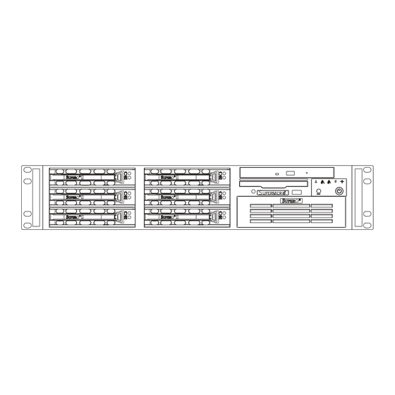
UPER ERVER 6023P-8R/6023P-8 Manual Slim-Line Control Panel/ Floppy Drive CD-ROM Drive System LEDs SCSI Drives (6) 5 1/4" Drive Bay System Reset Main Power 7 Low Profile PCI Slots Keyboard/Mouse Ports USB Ports COM1 Port VGA Port Ethernet Ports Figure 6-1. Chassis: Front and Rear Views (6023P-8R shown - the 6023P-8 has a single power supply module) Control Panel... -
Page 61: System Fans
System Fans Four 8-cm fans (and the active CPU heatsinks) provide all the cooling needed for the SuperServer 6023P-8R/6023P-8. It is very important that the chassis top cover is properly installed and making a good seal in order for the cooling air to circulate properly through the chassis and cool the compo- nents. -
Page 62: Drive Bay Installation/Removal
SCSI drives. Proceed to the next step for instructions. Note: You must use standard 1" high, 80-pin SCA SCSI drives in the SuperServer 6023P-8R/6023P-8. CD-ROM/Floppy Disk Drive: For installing/removing the CD-ROM or floppy disk drive, you will need to gain access to the inside of the server by removing the top cover of the chassis. -
Page 63: Scsi Drive Installation
Chapter 6: Advanced Chassis Setup SCSI Drive Installation Mounting a SCSI drive in a drive carrier: The SCSI drives are mounted in drive carriers to simplify their installation and removal from the chassis. These carriers also help promote proper airflow for the SCSI drive bays. For this reason, even empty carriers without SCSI drives installed must remain in the chassis to cool each drive evenly. - Page 64 UPER ERVER 6023P-8R/6023P-8 Manual Installing/removing hot-swap SCSI drives: The SCSI drive bays are located in the front of the chassis, making them easily accessible for installation and removal. The SCSI drives are hot- swap units, meaning that they can be installed and removed while the system is running.
-
Page 65: Installing A Component In The 5 1/4" Drive Bay
Chapter 6: Advanced Chassis Setup SCA Backplane The SCSI drives plug into a SAF-TE compliant SCA backplane that provides power, SCSI ID and bus termination. A RAID controller can be used with the SCA backplane to provide data security. The operating system you use must have RAID support to enable the hot-swap capability of the SCSI drive. -
Page 66: Cd-Rom And Floppy Drive Installation
UPER ERVER 6023P-8R/6023P-8 Manual Installing/removing 5 1/4" drive bay component A single 5 1/4" IDE drive bay is located in the front of the chassis, making it easily accessible for installation and removal. This component is not hot-swappable, meaning system power must be turned off before installing and/or removing them. -
Page 67: Power Supply: 6023P-8R
Chapter 6: Advanced Chassis Setup Power Supply: 6023P-8R The SuperServer 6023P-8R has a 400 watt redundant power supply con- sisting of two power modules. Each power supply module has an auto- switching capability, which enables it to automatically sense and operate at a 100V to 220V input voltage. -
Page 68: Power Supply: 6023P-8
UPER ERVER 6023P-8R/6023P-8 Manual Power Supply: 6023P-8 The SuperServer 6023P-8 has a single 400 watt power supply. This power supply has an auto-switching capability, which enables it to automatically sense and operate at a 100V to 220V input voltage. Power Supply Failure If the power supply unit fails, the system will shut down and you will need to replace the power supply unit. -
Page 69: Chapter 7: Bios
Chapter 7: BIOS Chapter 7 BIOS Introduction This chapter describes the PhoenixBIOS™ Setup utility for the X5DP8-G2. The Phoenix ROM BIOS is stored in a flash chip and can be easily upgraded using a floppy disk-based program. Note: Due to periodic changes to the BIOS, some settings may have been added or deleted and might not yet be recorded in this manual. -
Page 70: Running Setup
SUPERSERVER 6023P-8R/6023P-8 User's Manual Running Setup *Default settings are in bold text unless otherwise noted. The BIOS setup options described in this section are selected by choos- ing the appropriate text from the main BIOS Setup screen. All displayed text is described in this section, although the screen display is often all you need to understand how to set the options (see on next page). -
Page 71: Main Bios Setup Menu
Chapter 7: BIOS Main BIOS Setup Menu Phoenix BIOS Setup Utility Main Advanced Security Power Boot Exit Item Specific Help System Time [16:19:20] System Date [02/02/02] Legacy Diskette A: [1.44/1.25 MB] Legacy Diskette B: [Not Installed] " Primary Master [120 GB] "... -
Page 72: Legacy Diskette A
SUPERSERVER 6023P-8R/6023P-8 User's Manual Legacy Diskette A This setting allows the user to set the type of floppy disk drive installed as diskette A. The options are Disabled, 360Kb 5.25 in, 1.2MB 5.25 in, 720Kb 3.5 in, 1.44/1.25MB, 3.5 in and 2.88MB 3.5 in. - Page 73 Chapter 7: BIOS Type Selects the type of IDE hard drive. The options are Auto (allows BIOS automatically determine the hard drive's capacity, number of heads, etc.), a number from 1-39 to select a predetermined type of hard drive, CD-ROM and ATAPI Removable. Multi-Sector Transfers Select the number of transfer sectors.
-
Page 74: Advanced
SUPERSERVER 6023P-8R/6023P-8 User's Manual Advanced Setup Choose Advanced from the Phoenix BIOS Setup Utility main menu with the arrow keys. You should see the following display. The items with a triangle beside them have sub menus that can be accessed by highlighting the item and pressing <Enter>. - Page 75 Chapter 7: BIOS Quiet Boot This setting allows you to Enable or Disable the diagnostic screen during boot-up. Legacy USB Support This setting allows you to enable support for Legacy USB devices. The settings are Enabled and Disabled. Reset Configuration Data Options are Yes and No.
- Page 76 SUPERSERVER 6023P-8R/6023P-8 User's Manual Interrupt Select the IRQ (interrupt request) for serial port A. Options are IRQ3 and IRQ4. Serial Port B This setting allows you to assign control of serial port B. The options are Enabled (user defined), Disabled, Auto (BIOS controlled) and OS Controlled.
- Page 77 Chapter 7: BIOS Mode Specify the parallel port mode. Options are Output Only, Bi-directional, EPP and ECP. DMA Channel Specify the DMA channel. Options are DMA1 and DMA3. Floppy Disk Controller This setting allows you to assign control of the floppy disk controller. The options are Enabled (user defined), Disabled and Auto (BIOS controlled).
- Page 78 SUPERSERVER 6023P-8R/6023P-8 User's Manual ECC Configuration This setting lets you enable or disable ECC (Error Correction and Checking). The options are ECC and Disabled. ECC Error Type This setting lets you select which type of interrupt will be activated as a result of an ECC error.
- Page 79 Chapter 7: BIOS Split Lock Operations This setting allows you to Enable or Disable split lock operations. Hyper-threading This setting allows you to Enable or Disable hyper-threading. Enabling hyper-threading results in increased CPU performance. L3 Cache This setting allows you to Enable or Disable the L3 cache. KDMI Event Logging Access the submenu to make changes to the following settings.
- Page 80 SUPERSERVER 6023P-8R/6023P-8 User's Manual Clear All DMI Event Logs Highlight this item and press <Enter> to clear all DMI event logs. KConsole Redirection Access the submenu to make changes to the following settings. COM Port Address Specifies to redirect the console to On-board COMA or On-board COMB.
-
Page 81: Security
Chapter 7: BIOS Security Choose Security from the Phoenix BIOS Setup Utility main menu with the arrow keys. You should see the following display. Security setting options are displayed by highlighting the setting using the arrow keys and pressing <Enter>. All Security BIOS settings are described in this section. - Page 82 SUPERSERVER 6023P-8R/6023P-8 User's Manual Set Supervisor Password When the item "Set Supervisor Password" is highlighted, hit the <Enter> key. When prompted, type the Supervisor's password in the dialogue box to set or to change supervisor's password, which allows access to BIOS.
-
Page 83: Power
Chapter 7: BIOS Power Choose Power from the Phoenix BIOS Setup Utility main menu with the arrow keys. You should see the following display. Power setting options are displayed by highlighting the setting using the arrow keys and pressing <Enter>. All Power BIOS settings are described in this section. - Page 84 SUPERSERVER 6023P-8R/6023P-8 User's Manual Standby Timeout Use this setting to specify the period of system inactivity to transpire before entering the standby state. Options are Off, 16 sec, 32 sec, 48 sec, 1 min, 2 min, 4 min and 8 min.
-
Page 85: Boot
Chapter 7: BIOS Boot Choose Boot from the Phoenix BIOS Setup Utility main menu with the arrow keys. You should see the following display. Highlighting a setting with a + or - will expand or collapse that entry. See details on how to change the order and specs of boot devices in the Item Specific Help window. - Page 86 SUPERSERVER 6023P-8R/6023P-8 User's Manual +Hard Drive Highlight and press <Enter> to expand the field. See details on how to change the order and specs of hard drives in the Item Specific Help w i n d o w . Network Boot See details on how to change the order and specs of network boot devices in the Item Specific Help window.
-
Page 87: Pir
Chapter 7: BIOS Choose PIR from the Phoenix BIOS Setup Utility main menu with the arrow keys. You should see the following display. The items with a triangle beside them have sub menus that can be accessed by highlighting the item and pressing <Enter>. PIR stands for "Processor Info ROM", which allows BIOS to read certain information from the processors. - Page 88 SUPERSERVER 6023P-8R/6023P-8 User's Manual KProcessor Info ROM Data Highlight this and hit <Enter> to see PIR data on the following items: Header Info Processor Data Processor Core Data L3 Cache Data Package Data Part Number Data Thermal Reference Data Feature Data...
-
Page 89: Exit
Chapter 7: BIOS Chassis Fan 2 Processor Vcore 3.3V Standby 3.3V Vcc 5V Vcc 12V Vcc 1.8V Vcc -12V Vcc Exit Choose Exit from the Phoenix BIOS Setup Utility main menu with the arrow keys. You should see the following display. All Exit BIOS settings are described in this section. - Page 90 SUPERSERVER 6023P-8R/6023P-8 User's Manual Exit Saving Changes Highlight this item and hit <Enter> to save any changes you made and to exit the BIOS Setup utility. Exit Discarding Changes Highlight this item and hit <Enter> to exit the BIOS Setup utility without saving any changes you may have made.
-
Page 91: Appendix A: Bios Post Messages
Appendix A: BIOS POST Messages Appendix A BIOS POST Messages During the Power-On Self-Test (POST), the BIOS will check for problems. If a problem is found, the BIOS will activate an alarm or display a message. The following is a list of such BIOS messages. - Page 92 UPER ERVER 6023P-8R/6023P-8 Manual System CMOS checksum bad - Default configuration used System CMOS has been corrupted or modified incorrectly, perhaps by an application program that changes data stored in CMOS. The BIOS installed Default Setup Values. If you do not want these values, enter Setup and enter your own values.
- Page 93 Appendix A: BIOS POST Messages System cache error - Cache disabled RAM cache failed and BIOS disabled the cache. On older boards, check the cache jumpers. You may have to replace the cache. See your dealer. A disabled cache slows system performance considerably. CPU ID: CPU socket number for Multi-Processor error.
- Page 94 UPER ERVER 6023P-8R/6023P-8 Manual Fixed Disk n Fixed disk n (0-3) identified. Invalid System Configuration Data Problem with NVRAM (CMOS) data. I/O device IRQ conflict I/O device IRQ conflict error. PS/2 Mouse Boot Summary Screen: PS/2 Mouse installed. nnnn kB Extended RAM Passed Where nnnn is the amount of RAM in kilobytes successfully tested.
- Page 95 Appendix A: BIOS POST Messages Parity Check 2 nnnn Parity error found in the I/O bus. BIOS attempts to locate the address and display it on the screen. If it cannot locate the address, it displays ????. Press <F1> to resume, <F2> to Setup, <F3> for previous Displayed after any recoverable error message.
- Page 96 UPER ERVER 6023P-8R/6023P-8 Manual Notes...
-
Page 97: Appendix B: Bios Post Codes
Appendix B: BIOS POST Codes Appendix B BIOS POST Codes This section lists the POST (Power On Self Test) codes for the PhoenixBIOS. POST codes are divided into two categories: recoverable and terminal. Recoverable POST Errors When a recoverable type of error occurs during POST, the BIOS will display an POST code that describes the problem. - Page 98 UPER ERVER 6023P-8R/6023P-8R Manual POST Code Description Initialize keyboard controller 1-2-2-3 BIOS ROM checksum Initialize cache before memory Auto size 8254 timer initialization 8237 DMA controller initialization Reset Programmable Interrupt Controller 1-3-1-1 Test DRAM refresh 1-3-1-3 Test 8742 Keyboard Controller Set ES segment register to 4 GB Auto size DRAM Initialize POST Memory Manager...
- Page 99 Appendix B: BIOS POST Codes POST Code Description Initialize POST display service Display prompt “Press F2 to enter SETUP” Disable CPU cache Test RAM between 512 and 640 kB Test extended memory Test extended memory address lines Jump to UserPatch1 Configure advanced cache registers Initialize Multi Processor APIC Enable external and CPU caches...
- Page 100 UPER ERVER 6023P-8R/6023P-8R Manual POST Code Description Fix up Multi Processor table 1-2 Search for option ROMs. One long, two short beeps on checksum failure Check for SMART Drive (optional) Shadow option ROMs Set up Power Management Initialize security engine (optional) Enable hardware interrupts Determine number of ATA and SCSI drives Set time of day...
- Page 101 Appendix B: BIOS POST Codes POST Code Description Redirect Int 13h to Memory Technologies Devices such as ROM, RAM, PCMCIA, and serial disk Redirect Int 10h to enable remote serial video Re-map I/O and memory for PCMCIA Initialize digitizer and display message Unknown interrupt The following are for boot block in Flash ROM POST Code...
- Page 102 UPER ERVER 6023P-8R/6023P-8R Manual Notes...
-
Page 103: Appendix C: System Specifications
Appendix C: System Specifications Appendix C System Specifications Processors ® Single or dual Intel Xeon 604-pin processors to 2.80 GHz at a front side (system) bus speed of 533/400 MHz. Note: Please refer to the motherboard specifications pages on our web site (http:// www.supermicro.com/Product_page/product-m.htm) for updates on supported processors. - Page 104 UPER ERVER 6023P-8R/6023P-8 User's Manual Expansion Slots Six (6) 64-bit PCI-X slots (with optional speed/PCI-X and PCI settings) and one (1) SXB (128-bit Super Extended Bus) slot Power Supply Type: 2 (6023P-8R) or 1 (6023P-8) x 400W with +3.3V, +5V, +12V, - 5V and -12V main DC outputs and a 5V standby output Input Voltage: 100-220VAC (w/ ±...
Need help?
Do you have a question about the SUPERSERVER 6023P-8R and is the answer not in the manual?
Questions and answers