Table of Contents
Advertisement
Quick Links
Advertisement
Table of Contents

Related Manuals for Supero SUPERSERVER 6027B-URF


Summary of Contents for Supero SUPERSERVER 6027B-URF
- Page 1 ® UPER UPER ERVER 6027B-URF USER’S MANUAL...
- Page 2 This product, including software and docu- mentation, is the property of Supermicro and/or its licensors, and is supplied only under a license. Any use or reproduction of this product is not allowed, except as expressly permitted by the terms of said license.
-
Page 3: About This Manual
About This Manual This manual is written for professional system integrators and PC technicians. It provides information for the installation and use of the SuperServer 6027B-URF. Installation and maintainance should be performed by experienced technicians only. The SuperServer 6027B-URF is a high-end server based on the SC825TQ-R740UB 2U rackmount chassis and the X9DBU-iF dual processor serverboard. - Page 4 UPER ERVER 6027B-URF User's Manual Chapter 5: Advanced Serverboard Setup Chapter 5 provides detailed information on the X9DBU-iF serverboard, including the locations and functions of connections, headers and jumpers. Refer to this chapter when adding or removing processors or main memory and when reconfi guring the serverboard.
- Page 5 Preface Notes...
-
Page 6: Table Of Contents
UPER ERVER 6027B-URF User's Manual Table of Contents Chapter 1 Introduction Overview ......................1-1 Serverboard Features ..................1-2 Processors ...................... 1-2 Memory ......................1-2 UIO ........................1-2 SATA ......................1-2 Onboard Controllers/Ports ................1-2 Graphics Controller ..................1-2 Server Chassis Features ................1-3 System Power .................... - Page 7 Table of Contents Power ......................3-1 Control Panel LEDs ..................3-2 Information LED ....................3-2 NIC1 ........................ 3-2 NIC2 ........................ 3-2 HDD ......................... 3-3 Power ......................3-3 Drive Carrier LEDs ..................3-3 SATA Drives ....................3-3 Chapter 4 System Safety Electrical Safety Precautions ................
- Page 8 UPER ERVER 6027B-URF User's Manual Chapter 6 Advanced Chassis Setup Static-Sensitive Devices .................. 6-1 Precautions ..................... 6-1 Unpacking ....................... 6-1 Control Panel ....................6-2 System Fans ....................6-3 System Fan Failure ..................6-3 Replacing System Fans .................. 6-3 Drive Bay Installation/Removal ............... 6-4 Accessing the Drive Bays ................
-
Page 9: Chapter 1 Introduction
Chapter 1 Introduction Overview The SuperServer 6027B-URF is a high-end server comprised of two main subsys- tems: the SC825TQ-R740UB 2U server chassis and the X9DBU-iF dual processor serverboard. Please refer to our web site for information on operating systems that have been certifi... -
Page 10: Serverboard Features
ERVER 6027B-URF User's Manual Serverboard Features At the heart of the SuperServer 6027B-URF lies the X9DBU-iF, a dual processor serverboard based on the Intel® C602 chipset. Below are the main features of the X9DBU-iF. (See Figure 1-1 for a block diagram of the chipset). -
Page 11: Server Chassis Features
Chapter 1: Introduction Server Chassis Features The 6027B-URF is built upon the SC825TQ-R740UB chassis. Details on the chassis and on servicing procedures can be found in Chapter 6. The following is a general outline of the main features of the chassis. -
Page 12: System Block Diagram
UPER ERVER 6027B-URF User's Manual Figure 1-1. Intel C602 Chipset: System Block Diagram Note: This is a general block diagram. Please see Chapter 5 for details. #F-2 #F-1 #E-2 #C-2 #E-1 #C-1 #D-2 #B-2 #D-1 #B-1 CPU1 CPU2 #A-2 #A-1... -
Page 13: Contacting Supermicro
Super Micro Computer, Inc. 980 Rock Ave. San Jose, CA 95131 U.S.A. Tel: +1 (408) 503-8000 Fax: +1 (408) 503-8008 Email: marketing@supermicro.com (General Information) support@supermicro.com (Technical Support) Web Site: www.supermicro.com Europe Address: Super Micro Computer B.V. Het Sterrenbeeld 28, 5215 ML... - Page 14 UPER ERVER 6027B-URF User's Manual Notes...
-
Page 15: Chapter 2 Server Installation
Precautions in the next section. Preparing for Setup The box the SuperServer 6027B-URF was shipped in should include two sets of rail assemblies, two rail mounting brackets and the mounting screws you will need to install the system into the rack. Follow the steps in the order given to complete the installation process in a minimum amount of time. -
Page 16: Rack Precautions
UPER ERVER 6027B-URF User's Manual • This product is for installation only in a Restricted Access Location (dedicated equipment rooms, service closets and the like). • This product is not suitable for use with visual display work place devices acccording to §2 of the the German Ordinance for Work with Visual Display Units. -
Page 17: Rack Mounting Considerations
Chapter 2: Server Installation Rack Mounting Considerations Ambient Operating Temperature If installed in a closed or multi-unit rack assembly, the ambient operating tempera- ture of the rack environment may be greater than the ambient temperature of the room. Therefore, consideration should be given to installing the equipment in an environment compatible with the manufacturer’s maximum rated ambient tempera- ture (Tmra). -
Page 18: Installing The System Into A Rack
UPER ERVER 6027B-URF User's Manual Installing the System into a Rack This section provides information on installing the SC825 chassis into a rack unit with the quick-release rails provided. There are a variety of rack units on the market, which may mean the assembly procedure will differ slightly. You should also refer to the installation instructions that came with the rack unit you are using. - Page 19 Chapter 2: Server Installation Figure 2-1: Separating the Rack Rails Separating the Inner and Outer Rails Rail Assembly 1. Locate the rail assembly in the chassis packaging. 2. Extend the rail assembly by pulling it Extending the Rails outward. 3. Press the quick-release tab. 4.
-
Page 20: Outer Rack Rails
UPER ERVER 6027B-URF User's Manual Figure 2-2. Assembling the Outer Rails Outer Rack Rails Outer rails attach to the rack and hold the chassis in place. The outer rails for the SC825 chassis extend between 30 inches and 33 inches. - Page 21 Chapter 2: Server Installation Figure 2-3. Installing the Rack Rails Installing the Chassis into a Rack 1. Extend the outer rails as illustrated above. 2. Align the inner rails of the chassis with the outer rails on the rack. 3. Slide the inner rails into the outer rails, keeping the pressure even on both sides.
- Page 22 UPER ERVER 6027B-URF User's Manual Notes...
-
Page 23: Chapter 3 System Interface
Chapter 3: System Interface Chapter 3 System Interface Overview There are several LEDs on the control panel as well as others on the drive carri- ers to keep you constantly informed of the overall status of the system as well as the activity and health of specifi... -
Page 24: Control Panel Leds
SUPERSERVER 6027B-URF User's Manual Control Panel LEDs The control panel located on the front of the chassis has several LEDs. These LEDs provide you with critical information related to different parts of the system. This section explains what each LED indicates when illuminated and any corrective action you may need to take. -
Page 25: Hdd
Chapter 3: System Interface On the SuperServer 6027B-URF, this LED indicates hard drive and/or DVD-ROM drive activity when fl ashing. Power Indicates power is being supplied to the system's power supply units. This LED should normally be illuminated when the system is operating. - Page 26 SUPERSERVER 6027B-URF User's Manual Notes...
-
Page 27: Chapter 4 System Safety
System Safety Electrical Safety Precautions Basic electrical safety precautions should be followed to protect yourself from harm and the SuperServer 6027B-URF from damage: • Be aware of the locations of the power on/off switch on the chassis as well as the room's emergency power-off switch, disconnection switch or electrical outlet. -
Page 28: General Safety Precautions
Keep the area around the 6027B-URF clean and free of clutter. • The 6027B-URF weighs approximately 57 lbs (25.9 kg.) when fully loaded. When lifting the system, two people at either end should lift slowly with their feet spread out to distribute the weight. Always keep your back straight and lift with your legs. -
Page 29: Esd Precautions
Chapter 4: System Safety • After accessing the inside of the system, close the system back up and secure it to the rack unit with the retention screws after ensuring that all connections have been made. ESD Precautions Electrostatic discharge (ESD) is generated by two objects with different electrical charges coming into contact with each other. -
Page 30: Operating Precautions
UPER ERVER 6027B-URF User's Manual Operating Precautions Care must be taken to assure that the chassis cover is in place when the 6027B- URF is operating to assure proper cooling. Out of warranty damage to the system can occur if this practice is not strictly followed. -
Page 31: Chapter 5 Advanced Serverboard Setup
Chapter 5: Advanced Serverboard Setup Chapter 5 Advanced Serverboard Setup This chapter covers the steps required to install processors and heatsinks to the X9DBU-iF serverboard, connect the data and power cables and install add-on cards. All serverboard jumpers and connections are described and a layout and quick reference chart are included in this chapter. -
Page 32: Processor And Heatsink Installation
CPU socket cap is in place and none of the socket pins are bent; otherwise, contact your retailer immediately. • Refer to the Supermicro web site for updates on CPU support. Installing an LGA 1356 Processor 1. Press the socket clip to release the load plate covering the CPU socket from its locked position. - Page 33 Chapter 5: Advanced Serverboard Setup 5. Align the CPU key, which is a semi- circle cutout, against the socket key, which is the notch below the gold color dot on the side of the socket. 6. Align pin 1 of the CPU against pin 1 of the CPU socket.
-
Page 34: Installation And Removal Of The Heatsink
UPER ERVER 6027B-URF User's Manual Installation and Removal of the Heatsink Installing the Heatsink 1. Do not apply any thermal grease to the heatsink or the CPU die; the required amount has already been applied. 2. Place the heatsink on top of the CPU so that the four mounting holes are aligned with those on the retention mechanism. -
Page 35: Connecting Cables
Chapter 5: Advanced Serverboard Setup Connecting Cables Now that the processors are installed, the next step is to connect the cables to the serverboard. These include the data (ribbon) cables for the peripherals and control panel and the power cables. Connecting Data Cables The cables used to transfer data from the peripheral devices have been carefully routed in preconfi... -
Page 36: I/O Ports
UPER ERVER 6027B-URF User's Manual Figure 5-1. Front Control Panel Header Pins (JF1) Ground FP PWRLED 3.3 V HDD LED ID_UID_SW/3/3V Stby NIC1 Link LED NIC1 Activity LED NIC2 Activity LED NIC2 Link LED Blue+ (OH/Fan Fail/ Red+ (Blue LED Cathode) -
Page 37: Installing Memory
Chapter 5: Advanced Serverboard Setup Installing Memory Note: Check the Supermicro web site for recommended memory modules. CAUTION Exercise extreme care when installing or removing DIMM modules to prevent any possible damage. Installing DIMMs 1. Insert the desired number of DIMMs into the memory slots, starting with slot P1-DIMMA1. - Page 38 UPER ERVER 6027B-URF User's Manual Processor & Memory Module Population Confi guration For memory to work properly, follow the tables below for memory installation. Processors and their Corresponding Memory Modules CPU# Corresponding DIMM Modules CPU 1 DIMMA1 DIMMA2 DIMMB1 DIMMB2...
- Page 39 1066 1066 DRx8 Note: For detailed information on memory support and updates, please refer to the SMC Recom- mended. Memory List posted on our website at http://www.supermicro.com/support/resources/ mem.cfm. Populating RDIMM (ECC) Memory Modules Intel E5-2400 Series Processor RDIMM Memory Support...
- Page 40 1333 1333 Note: For detailed information on memory support and updates, please refer to the SMC Recommended Memory List posted on our website at http://www.supermicro. com/support/resources/mem.cfm. Other Important Notes and Restrictions • For the memory modules to work properly, please install DIMM modules of the same type, same speed and same operating frequency on the serverboard.
-
Page 41: Adding Pci Expansion Cards
Chapter 5: Advanced Serverboard Setup Adding PCI Expansion Cards PCI Expansion Slots Two riser cards are used to support PCI expansion cards included with the system. The RSC-R2UU-2E4R riser card can support two PCI-Express x4 expansion cards. The RSC-R2UU-U2E4E8G riser card can support one UIO card, two PCI-Express x4 and one PCI-Express x8 expansion cards. -
Page 42: Serverboard Details
UPER ERVER 6027B-URF User's Manual Serverboard Details Figure 5-4. SUPER X9DBU-iF Layout LED3 USB0/1 COM1 JPL1 LAN2 LAN1 KB/MOUSE JPW4 CTRL IPMI_LAN 82580 Processor LED1 CTRL JI2C1 JI2C2 XDP_CPU JPW3 JPG1 Battery XDP_PCH Processor JPW2 I-SATA5 I-SATA4 I-SATA3 Intel IOH... - Page 43 Chapter 5: Advanced Serverboard Setup Jumper Description Default Setting JBT1 Clear CMOS See Section 5-9 C1/JI SMB to PCI-E Slots Open (Normal) JPB1 BMC Enable/Disable Pins 1-2 (Enabled) JPG1 VGA Enable/Disable Pins 1-2 (Enabled) JPL1 LAN1/LAN2 Enable/Disable Pins 1-2 (Enabled) JVRM_JI C1/JI C Bus to CPU1/2 VRMs...
-
Page 44: Connector Defi Nitions
UPER ERVER 6027B-URF User's Manual Connector Defi nitions ATX Power 24-pin Connector Pin Defi nitions Power Connectors Pin# Defi nition Pin # Defi nition +3.3V +3.3V A 2 4 - p i n m a i n p o w e r s u p p l y -12V +3.3V... - Page 45 Chapter 5: Advanced Serverboard Setup HDD LED The HDD (IDE Hard Disk Drive) LED HDD LED Pin Defi nitions (JF1) connection is located on pins 13 and Pin# Defi nition 14 of JF1. Attach the IDE hard drive LED cable to display disk activity. HD Active Refer to the table on the right for pin defi...
- Page 46 UPER ERVER 6027B-URF User's Manual Power Fail LED Power Fail LED Pin Defi nitions (JF1) The Power Fail LED connection is Pin# Defi nition located on pins 5 and 6 of JF1. Refer to the table on the right for pin defi ni- Ground tions.
- Page 47 Chapter 5: Advanced Serverboard Setup Serial Port Pin Defi nitions (COM1, COM2) Serial Ports Pin # Defi nition Pin # Defi nition The COM1 serial port is located on the IO backplane. COM2 is a header on the serverboard (see serverboard layout for location).
- Page 48 UPER ERVER 6027B-URF User's Manual PWR LED Connector Power LED/Speaker Pin Defi nitions Pin Setting Defi nition On the JD1 header, pins 1-3 are for Pin 1 Anode (+) a power LED and pins 4-7 are for an external speaker. See the table on the...
- Page 49 Chapter 5: Advanced Serverboard Setup Power SMB (I C) Connector PWR SMB Pin Defi nitions The Power System Management Bus Pin# Defi nition C) header (JPI C) is used to moni- Clock tor the power supply, fan and system Data temperatures.
- Page 50 UPER ERVER 6027B-URF User's Manual Standby Power Standby Power Pin Defi nitions The Standby Power header is located Pin# Defi nition at JSTBY1 on the serverboard. See +5V Standby the table on the right for pin defi ni- Ground tions. (You must also have a cable to Wake-up use this feature.)
-
Page 51: Jumper Settings
Chapter 5: Advanced Serverboard Setup Jumper Settings Explanation of Jumpers To modify the operation of the serverboard, jumpers can be used Connector to choose between optional settings. Pins Jumpers create shorts between two pins to change the function of the Jumper connector. - Page 52 UPER ERVER 6027B-URF User's Manual LAN Enable/Disable LAN Enable/Disable Change the setting of jumper JPL1 to Jumper Settings (JPL1) enable or disable the onboard Ether- Jumper Setting Defi nition net (RJ45) ports LAN1 and LAN2. See Pins 1-2 Enabled the table on the right for jumper set-...
- Page 53 Chapter 5: Advanced Serverboard Setup BMC Enable Jumper JPB1 allows you to enable the BMC Enable Jumper Settings embedded the Nuvoton WPCM450R Jumper Setting Defi nition BMC (Baseboard Management) con- Pins 1-2 BMC Enable troller to provide IPMI 2.0/KVM support Pins 2-3 Normal (Default) on the serverboard.
-
Page 54: 5-10 Onboard Indicators
UPER ERVER 6027B-URF User's Manual 5-10 Onboard Indicators LAN1/LAN2 LEDs The Ethernet ports (located beside the LAN LED VGA port) have two LEDs. On each Connection Speed Indicator LED Color Defi nition Gigabit LAN port, one LED indicates No connection or 10 Mb/s... -
Page 55: 5-11 Sata Port Connections
Chapter 5: Advanced Serverboard Setup Rear UID LED UID LED LED3 is the rear UID LED, located on Status the rear of the serverboard. This LED Color/State OS Status is used in conjunction with the rear Blue: On Windows OS Unit Identifi... -
Page 56: 5-12 Installing Software
5-12 Installing Software After the hardware has been installed, you should fi rst install the operating system and then the drivers. The necessary drivers are all included on the Supermicro CDs that came packaged with your serverboard. Driver/Tool Installation Display Screen Note: Click the icons showing a hand writing on paper to view the readme fi... -
Page 57: Supero Doctor Iii
Chapter 5: Advanced Serverboard Setup Supero Doctor III The Supero Doctor III program is a Web based management tool that supports re- mote management capability. It includes Remote and Local Management tools. The local management is called SD III Client. The Supero Doctor III program included on the CDROM that came with your serverboard allows you to monitor the environment and operations of your system. - Page 58 Supero Doctor III Interface Display Screen (Remote Control) Note: SD III Software Revision 1.0 can be downloaded from our Web Site at: ftp:// ftp.supermicro.com/utility/Supero_Doctor_III/. You can also download SDIII User's Guide at: http://www.supermicro.com/PRODUCT/Manuals/SDIII/UserGuide.pdf. For Linux, we will still recommend Supero Doctor II.
-
Page 59: Chapter 6 Advanced Chassis Setup
Chapter 6: Advanced Chassis Setup Chapter 6 Advanced Chassis Setup This chapter covers the steps required to install components and perform main- tenance on the SC825TQ-R740UB chassis. For component installation, follow the steps in the order given to eliminate the most common problems encountered. If some steps are unnecessary, skip ahead to the step that follows. -
Page 60: Control Panel
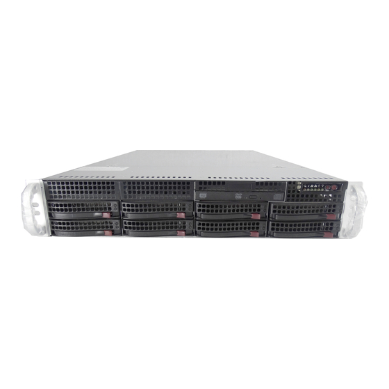
UPER ERVER 6027B-URF User's Manual Figure 6-1. Front and Rear Chassis Views Optional 3.5" Drive Bays (2) Slim DVD-ROM Drive USB Ports, COM Port Control Panel SATA Drives (8) System Reset Main Power Keyboard/Mouse Ports IPMI LAN 4 Standard Size PCI Slots... -
Page 61: System Fans
Installing a New Fan 1. Replace the failed fan with an identical 8-cm, 12 volt fan (available from Supermicro). 2. Position the new fan into the space vacated by the failed fan previously re- moved. A "click" can be heard when the fan is fully installed in place and the power connections are made. -
Page 62: Drive Bay Installation/Removal
SAS/SATA drives. Proceed to the next step for instructions. You must use standard 1" high, SAS/SATA drives in the system. Note: Refer to the following ftp site for setup guidelines: <ftp://ftp.supermicro.com/ driver/SAS/LSI/LSI_SAS_EmbMRAID_SWUG.pdf> and Supermicro's web site for additional inmformation <... -
Page 63: Sas/Sata Drive Installation
Chapter 6: Advanced Chassis Setup SAS/SATA Drive Installation These drives are mounted in carriers to simplify their installation and removal from the chassis. The carriers also help promote proper airfl ow for the drives. For this reason, even empty carriers without hard drives installed must remain in the chassis. Note: SAS drives are supported only with a SAS UIO controller card installed. -
Page 64: Hard Drive Backplane
UPER ERVER 6027B-URF User's Manual Figure 6-4. Removing a SAS/SATA Drive Carrier Handle Release Button Important: All of the drive carriers must remain in the drive bays to maintain proper cooling airfl ow. Hard Drive Backplane The hard drives plug into a backplane that provides power, drive ID and bus termi- nation. -
Page 65: Dvd-Rom Installation
The top cover of the chassis must be opened to gain full access to the DVD-ROM drive bay. The 6027B-URF accomodates only slim type DVD-ROM drives. Side mounting brackets are typically needed to mount a slim DVD-ROM drive in the server. -
Page 66: Power Supply
ERVER 6027B-URF User's Manual Power Supply The SuperServer 6027B-URF has two 740 watt power supply modules to provide redundant power. Each power supply module has an auto-switching capability, which enables it to automatically sense and operate at a 100V - 240V input voltage. -
Page 67: Chapter 7 Bios
Chapter 7: BIOS Chapter 7 BIOS Introduction This chapter describes the AMI BIOS Setup utility for the X9DBU-3F/X9DBU-iF. It also provides the instructions on how to navigate the AMI BIOS Setup utility screens. The AMI ROM BIOS is stored in a Flash EEPROM and can be easily updated. Starting BIOS Setup Utility To enter the AMI BIOS Setup utility screens, press the <Del>... -
Page 68: How To Change The Confi Guration Data
UPER ERVER 6027B-URF User's Manual How To Change the Confi guration Data The confi guration data that determines the system parameters may be changed by entering the AMI BIOS Setup utility. This Setup utility can be accessed by pressing <Delete> at the appropriate time during system boot. - Page 69 This item displays the system date in Day MM/DD/YY format (e.g. Wed 10/12/2012). System Time This item displays the system time in HH:MM:SS format (e.g. 15:32:52). Supermicro X9DBU Version This item displays the SMC version of the BIOS ROM used in this system.
-
Page 70: Advanced Setup Confi Gurations
UPER ERVER 6027B-URF User's Manual Advanced Setup Confi gurations Use the arrow keys to select Advanced Setup and press <Enter> to access the following submenu items. Boot Features Quiet Boot This feature allows the user to select bootup screen display between POST mes- sages and the OEM logo. - Page 71 Chapter 7: BIOS Interrupt 19 Capture Interrupt 19 is the software interrupt that handles the boot disk function. When this item is set to Enabled, the ROM BIOS of the host adaptors will "capture" Interrupt 19 at bootup and allow the drives that are attached to these host adaptors to function as bootable disks.
- Page 72 UPER ERVER 6027B-URF User's Manual • CPU Signature • Microcode Patch • CPU Stepping • Maximum CPU Speed • Minimum CPU Speed • Processor Cores • Intel HT (Hyper-Threading) Technology • Intel VT-x Technology • Intel SMX Technology • L1 Data Cache •...
- Page 73 Chapter 7: BIOS Hyper-threading Select Enabled to support Intel Hyper-threading Technology to enhance CPU per- formance. The options are Enabled and Disabled. Active Processor Cores Set to Enabled to use a processor's second core and above. (Please refer to Intel's website for more information.) The options are All, 1, and 2.
- Page 74 UPER ERVER 6027B-URF User's Manual DCU IP Prefetcher Select Enabled for DCU (Data Cache Unit) IP Prefetcher support, which will prefetch IP addresses to improve network connectivity and system performance. The options are Enabled and Disabled. ® Intel Virtualization Technology (Available when supported by the CPU)
- Page 75 Chapter 7: BIOS CPU C6 Report (Available when Power Technology is set to Custom) Select Enabled to allow the BIOS to report the CPU C6 State (ACPI C3) to the operating system. During the CPU C6 State, the power to all cache is turned off.
-
Page 76: North Bridge
UPER ERVER 6027B-URF User's Manual Short Duration Power Limit During Turbo Mode, the system may exceed the processors default power setting and exceed the Short Duration Power limit. By increasing this value, the processor can provide better performance for short duration. This item displays the time period during which short duration power is maintained. - Page 77 Chapter 7: BIOS Port 3A Link Speed Select GEN1 to enable PCI-Exp Generation 1 support for Port 3A. Select GEN2 to enable PCI-Exp Generation 2 support for Port 3A. Select GEN3 to enable PCI-Exp Generation 3 support for Port 3A. The options are GEN1, GEN2, and GEN3.
- Page 78 UPER ERVER 6027B-URF User's Manual SXB1, SXB2 Slot CTLE Value Use this feature to select the PCIE GEN3 CTLE value. The default value is Auto. QPI Confi guration Current QPI Link Speed This item displays the current status of the QPI Link.
- Page 79 Chapter 7: BIOS DIMM Information This section displays the following DIMM information. Memory Mode When Independent is selected, all DIMMs are available to the operating system. When Mirroring is selected, the motherboard maintains two identical copies of all data in memory for data backup. When Lockstep is selected, the motherboard uses two areas of memory to run the same set of operations in parallel.
- Page 80 UPER ERVER 6027B-URF User's Manual source). Memory is updated as well. Select Enabled to use Demand Scrubbing for ECC memory correction. The options are Enabled and Disabled. Data Scrambling Select Enabled to enable data scrambling to ensure data security and integrity.
- Page 81 Chapter 7: BIOS Port 60/64 Emulation Select Enabled to enable I/O port 60h/64h emulation support for the legacy USB keyboard so that it can be fully supported by the operating systems that does not recognize a USB device. The options are Disabled and Enabled. EHCI Hand-Off This item is for operating systems that do not support Enhanced Host Controller Interface (EHCI) hand-off.
- Page 82 UPER ERVER 6027B-URF User's Manual Port 0~5 Hot Plug Select Enabled to enable hot-plug support for a particular port, which will allow the user to change a hardware component or device without shutting down the system. The options are Enabled and Disabled.
- Page 83 Chapter 7: BIOS PCI Latency Timer Use this feature to set the latency Timer of each PCI device installed on a PCI bus. Select 64 to set the PCI latency to 64 PCI clock cycles. The options are 32, 64, 96, 128, 160, 192, 224 and 248.
- Page 84 UPER ERVER 6027B-URF User's Manual Load Onboard LAN1 Option ROM/Load Onboard LAN2 Option ROM Select Enabled to enable the onboard LAN1 Option ROM~LAN2 Option ROM. This is to boot the computer using a network device. The default setting for LAN1 Op- tion ROM is Enabled, and the default setting for LAN2 Option ROM is Disabled.
-
Page 85: Serial Port Console Redirection
Chapter 7: BIOS Device Settings This item displays the settings of Serial Port 2. Change Settings This option specifi es the base I/O port address and the Interrupt Request address of Serial Port 1. Select Disabled to prevent the serial port from accessing any system resources. - Page 86 UPER ERVER 6027B-URF User's Manual Bits Per second Use this feature to set the transmission speed for a serial port used in Console Redirection. Make sure that the same speed is used in the host computer and the client computer. A lower transmission speed may be required for long and busy lines.
- Page 87 Chapter 7: BIOS Legacy OS Redirection Resolution Use this feature to select the number of rows and columns used in Console Redirection for legacy OS support. The options are 80x24 and 80x25. Putty KeyPad This feature selects Function Keys and KeyPad settings for Putty, which is a terminal emulator designed for the Windows OS.
-
Page 88: Acpi Settings
UPER ERVER 6027B-URF User's Manual Flow Control This feature allows the user to set the fl ow control for Console Redirection to prevent data loss caused by buffer overfl ow. Send a "Stop" signal to stop send- ing data when the receiving buffer is full. Send a "Start" signal to start sending data when the receiving buffer is empty. - Page 89 Chapter 7: BIOS Trusted Computing (Available when a TPM device is detected by the BIOS) Confi guration TPM Support Select Enabled on this item and enable the TPM jumper on the motherboard to enable TPM support to improve data integrity and network security. The options are Enabled and Disabled.
- Page 90 UPER ERVER 6027B-URF User's Manual Chipset: TXT (Trusted Execution Technology) Feature Intel TXT (LT-SX) Confi guration This feature displays the following TXT confi guration setting. TXT (LT-SX) Support: This item indicates if the Intel TXT support is enabled or disabled. The default setting is Disabled.
-
Page 91: Event Logs
Chapter 7: BIOS Event Logs Use this feature to confi gure Event Log settings. Change SMBIOS Event Log Settings This feature allows the user to confi gure SMBIOS Event settings. Enabling/Disabling Options SMBIOS Event Log Select Enabled to enable SMBIOS (System Management BIOS) Event Logging during system boot. - Page 92 UPER ERVER 6027B-URF User's Manual Erasing Settings Erase Event Log Select Enabled to erase the SMBIOS (System Management BIOS) Event Log, which is completed before an event logging is initialized upon system reboot. The options are No, Yes, next reset, and Yes, every reset.
-
Page 93: Ipmi
Chapter 7: BIOS IPMI Use this feature to confi gure Intelligent Platform Management Interface (IPMI) settings. IPMI Firmware Revision This item indicates the IPMI fi rmware revision used in your system. IPMI Status This item indicates the status of the IPMI fi rmware installed in your system. System Event Log Enabling/Disabling Options SEL Components... - Page 94 UPER ERVER 6027B-URF User's Manual When SEL is Full This feature allows the user to decide what the BIOS should do when the system event log is full. Select Erase Immediately to erase all events in the log when the system event log is full.
-
Page 95: Boot
Chapter 7: BIOS Gateway IP Address This item displays the Gateway IP address for this computer. This should be in decimal and in dotted quad form (i.e., 192.168.10.253). Boot This submenu allows the user to confi gure the following boot settings for the system. -
Page 96: Security
UPER ERVER 6027B-URF User's Manual Security This menu allows the user to confi gure the following security settings for the system. Administrator Password Use this feature to set the Administrator Password which is required to enter the BIOS setup utility. The length of the password should be from 3 characters to 20 characters long. -
Page 97: Save & Exit
Chapter 7: BIOS Save & Exit This submenu allows the user to confi gure the Save and Exit settings for the system. Discard Changes and Exit Select this option to quit the BIOS Setup without making any permanent changes to the system confi guration, and reboot the computer. Select Discard Changes and Exit, and press <Enter>. - Page 98 UPER ERVER 6027B-URF User's Manual Discard Changes Select this feature and press <Enter> to discard all the changes and return to the BIOS setup. When the dialog box appears, asking you if you want to load previ- ous values, select Yes to load the values previous saved, or select No to keep the changes you've made so far.
-
Page 99: Appendix A Bios Error Beep Codes
Appendix A: BIOS POST Error Codes Appendix A BIOS Error Beep Codes During the POST (Power-On Self-Test) routines, which are performed at each system boot, errors may occur. Non-fatal errors are those which, in most cases, allow the system to continue to boot. - Page 100 UPER ERVER 6027B-URF User's Manual Notes...
-
Page 101: Appendix B System Specifi Cations
Appendix B: System Specifi cations Appendix B System Specifi cations Processors Single or dual Intel® E5-2400 Series processors in LGA1356 sockets Note: Please refer to our web site for a complete listing of supported processors. Chipset Intel C602 chipset BIOS 128 Mb AMI®... - Page 102 UPER ERVER 6027B-URF User's Manual Chassis SC825TQ-R740UB (2U rackmount) Dimensions: (WxHxD) 16.8 x 3.5 x 25.5 in. (427 x 89 x 648 mm) Weight Gross (Bare Bone): 35 lbs. (15.9 kg.) System Cooling Three 8-cm system cooling fans System Input Requirements AC Input Voltage: 100 - 240V AC auto-range Rated Input Current: 9 - 3.5A max...
- Page 103 Appendix B: System Specifi cations Notes...
- Page 104 ERVER 6027B-URF User's Manual (continued from front) The products sold by Supermicro are not intended for and will not be used in life support systems, medical equipment, nuclear facilities or systems, aircraft, aircraft devices, aircraft/emergency com- munication devices or other critical systems whose failure to perform be reasonably expected to result in signifi...
Need help?
Do you have a question about the SUPERSERVER 6027B-URF and is the answer not in the manual?
Questions and answers