Table of Contents
Advertisement
Quick Links
Advertisement
Table of Contents

Related Manuals for Supero SUPERSERVER 6027R-TRF


Summary of Contents for Supero SUPERSERVER 6027R-TRF
- Page 1 UPER ® SUPERSERVER 6027R-TRF USER'S MANUAL Revision 1.0a...
- Page 2 The information in this User’s Manual has been carefully reviewed and is believed to be accurate. The vendor assumes no responsibility for any inaccuracies that may be contained in this document, makes no commitment to update or to keep current the information in this manual, or to notify any person or organization of the updates.
-
Page 3: About This Manual
About This Manual This manual is written for professional system integrators and PC technicians. It provides information for the installation and use of the SUPERSERVER 6027R-TRF Installation and maintainance should be performed by experienced technicians only. The SUPERSERVER 6027R-TRF is a high-end server based on the SC825TS-R740LPBP 2U rackmount chassis and the X9DRi-F dual processor serverboard. - Page 4 SUPERSERVER 6027R-TRF USER'S MANUAL Chapter 6: Advanced Chassis Setup Refer to Chapter 6 for detailed information on the SC825TS-R740LPBP server chassis. You should follow the procedures given in this chapter when installing, removing or reconfi guring SAS/SATA or peripheral drives and when replacing system power supply units and cooling fans.
- Page 5 Preface Notes...
-
Page 6: Table Of Contents
SUPERSERVER 6027R-TRF USER'S MANUAL Table of Contents Chapter 1 Introduction Overview ......................1-1 Serverboard Features ..................1-2 Processors ...................... 1-2 Memory ......................1-2 Serial ATA ....................... 1-2 Onboard Controllers/Ports ................1-2 Graphics Controller ..................1-2 Other Features ....................1-3 Server Chassis Features ................1-3 System Power .................... - Page 7 Table of Contents Installing the Inner Rail Extension ..............2-4 Outer Rack Rails ..................... 2-6 Checking the Serverboard Setup ..............2-8 Checking the Drive Bay Setup ..............2-10 Chapter 3 System Interface Overview ......................3-1 Control Panel Buttons ..................3-1 Reset .......................
- Page 8 SUPERSERVER 6027R-TRF USER'S MANUAL Serverboard Details ..................5-14 H8DGU(-F) Quick Reference ................ 5-15 Connector Defi nitions ................... 5-16 Jumper Settings .................... 5-24 Explanation of Jumpers ................5-24 5-10 Onboard Indicators ..................5-26 5-11 SATA Drive Connections ................5-27 5-13 Installing Drivers .................... 5-28 Supero Doctor III ...................
-
Page 9: Chapter 1 Introduction
Chapter 1 Introduction Overview The SUPERSERVER 6027R-TRF is a high-end server comprised of two main subsystems: the SC825TS-R740LPBP 2U server chassis and the X9DRi-F dual processor serverboard. Please refer to our web site for information on operating systems that have been certifi ed for use with the system (www.supermicro.com). -
Page 10: Serverboard Features
SUPERSERVER 6027R-TRF USER'S MANUAL Serverboard Features At the heart of the SUPERSERVER 6027R-TRF lies the X9DRi-F, a dual processor serverboard based on the Intel PCH C602/C606 chipset. Below are the main features of the X9DRi-F. (See Figure 1-1 for a block diagram of the chipset). -
Page 11: Other Features
See section 5-6 for further details.) Front Control Panel The control panel on the SUPERSERVER 6027R-TRF provides you with system monitoring and control. LEDs indicate system power, HDD activity, network activity, system overheat and power supply failure. A main power button and a system reset button are also included. -
Page 12: I/O Backplane
SUPERSERVER 6027R-TRF USER'S MANUAL I/O Backplane The SC825TS-R740LPBP is an ATX form factor chassis designed to be used in a 2U rackmount confi guration. The I/O backplane provides four standard-size add-on card slots, one COM port, a VGA port, two USB 2.0 ports, PS/2 mouse and keyboard ports, a dedicated IPMI LAN port and two gigabit Ethernet ports. - Page 13 Chapter 1: Introduction Figure 1-1. Intel PCH C602/C606 Chipset: System Block Diagram Note: This is a general block diagram. Please see Chapter 5 for details. #0-6 #0-5 #1-6 #0-4 #1-5 #0-3 #1-4 #0-2 #1-3 #0-1 #1-2 E5-2600 Series E5-2600 Series #1-1 Processor Processor...
-
Page 14: Contacting Supermicro
SUPERSERVER 6027R-TRF USER'S MANUAL Contacting Supermicro Headquarters Address: Super Micro Computer, Inc. 980 Rock Ave. San Jose, CA 95131 U.S.A. Tel: +1 (408) 503-8000 Fax: +1 (408) 503-8008 Email: marketing@supermicro.com (General Information) support@supermicro.com (Technical Support) Web Site: www.supermicro.com Europe Address: Super Micro Computer B.V. -
Page 15: Chapter 2 Server Installation
Unpacking the System You should inspect the box the SUPERSERVER 6027R-TRF was shipped in and note if it was damaged in any way. If the server itself shows damage you should fi... -
Page 16: Warnings And Precautions
SUPERSERVER 6027R-TRF USER'S MANUAL • This product is for installation only in a Restricted Access Location (dedicated equipment rooms, service closets and the like). • This product is not suitable for use with visual display work place devices acccording to §2 of the the German Ordinance for Work with Visual Display Units. -
Page 17: Rack Mounting Considerations
Chapter 2: Server Installation Rack Mounting Considerations Ambient Operating Temperature If installed in a closed or multi-unit rack assembly, the ambient operating temperature of the rack environment may be greater than the ambient temperature of the room. Therefore, consideration should be given to installing the equipment in an environment compatible with the manufacturer’s maximum rated ambient temperature (Tmra). -
Page 18: Installing The System Into A Rack
SUPERSERVER 6027R-TRF USER'S MANUAL Installing the System into a Rack This section provides information on installing the SC825 chassis into a rack unit with the quick-release rails provided. There are a variety of rack units on the market, which may mean the assembly procedure will differ slightly. You should also refer to the installation instructions that came with the rack unit you are using. - Page 19 Chapter 2: Server Installation Figure 2-1: Separating the Rack Rails Separating the Inner and Outer Rails Rail Assembly 1. Locate the rail assembly in the chassis packaging. 2. Extend the rail assembly by Extending the Rails pulling it outward. 3. Press the quick-release tab. 4.
-
Page 20: Outer Rack Rails
SUPERSERVER 6027R-TRF USER'S MANUAL Figure 2-2. Assembling the Outer Rails Outer Rack Rails Outer rails attach to the rack and hold the chassis in place. The outer rails for the SC825 chassis extend between 30 inches and 33 inches. Installing the Outer Rails to the Rack 1. - Page 21 Chapter 2: Server Installation Figure 2-3. Installing the Rack Rails Installing the Chassis into a Rack 1. Extend the outer rails as illustrated above. 2. Align the inner rails of the chassis with the outer rails on the rack. 3. Slide the inner rails into the outer rails, keeping the pressure even on both sides.
-
Page 22: Checking The Serverboard Setup
SUPERSERVER 6027R-TRF USER'S MANUAL Checking the Serverboard Setup After you install the 6027R-TRF in the rack, you will need to open the unit to make sure the serverboard is properly installed and all the connections have been made. Accessing the inside of the System 1. - Page 23 Chapter 2: Server Installation Figure 2-3. Accessing the Inside of the System...
-
Page 24: Checking The Drive Bay Setup
SUPERSERVER 6027R-TRF USER'S MANUAL Checking the Drive Bay Setup Next, you should check to make sure the peripheral drives and the SAS/SATA drives have been properly installed and all connections have been made. Checking the Drives 1. All drives are accessable from the front of the server. For servicing the DVD- ROM, you will need to remove the top chassis cover. -
Page 25: Chapter 3 System Interface
Chapter 3: System Interface Chapter 3 System Interface Overview There are several LEDs on the control panel of the 6027R-TRF server as well as others on the drive carriers to keep you constantly informed of the overall status of the system as well as the activity and health of specifi c components. There are also two buttons on the chassis control panel. -
Page 26: Control Panel Leds
SUPERSERVER 6027R-TRF USER'S MANUAL Control Panel LEDs The control panel located on the front of the chassis has several LEDs. These LEDs provide you with critical information related to different parts of the system. This section explains what each LED indicates when illuminated and any corrective action you may need to take. -
Page 27: Hdd
Chapter 3: System Interface On the SUPERSERVER 6027R-TRF, this LED indicates hard drive and/or DVD- ROM drive activity when fl ashing. Power Indicates power is being supplied to the system's power supply units. This LED should normally be illuminated when the system is operating. - Page 28 SUPERSERVER 6027R-TRF USER'S MANUAL Notes...
-
Page 29: Chapter 4 System Safety
System Safety Electrical Safety Precautions Basic electrical safety precautions should be followed to protect yourself from harm and the SUPERSERVER 6027R-TRF from damage: • Be aware of the locations of the power on/off switch on the chassis as well as the room's emergency power-off switch, disconnection switch or electrical outlet. -
Page 30: General Safety Precautions
SUPERSERVER 6027R-TRF USER'S MANUAL • This product may be connected to an IT power system. In all cases, make sure that the unit is also reliably connected to Earth (ground). • Serverboard Battery: CAUTION - There is a danger of explosion if the onboard battery is installed upside down, which will reverse its polarites (see Figure 4-1). -
Page 31: Esd Precautions
Chapter 4: System Safety • Remove any jewelry or metal objects from your body, which are excellent metal conductors that can create short circuits and harm you if they come into contact with printed circuit boards or areas where power is present. •... -
Page 32: Operating Precautions
SUPERSERVER 6027R-TRF USER'S MANUAL Operating Precautions Care must be taken to assure that the chassis cover is in place when the 6027R-TRF is operating to assure proper cooling. Out of warranty damage to the system can occur if this practice is not strictly followed. -
Page 33: Chapter 5 Advanced Serverboard Setup
Chapter 5: Advanced Serverboard Setup Chapter 5 Advanced Serverboard Setup This chapter covers the steps required to install processors and heatsinks to the X9DRi-F serverboard, connect the data and power cables and install add-on cards. All serverboard jumpers and connections are described and a layout and quick reference chart are included in this chapter. -
Page 34: Processor And Heatsink Installation
SUPERSERVER 6027R-TRF USER'S MANUAL Processor and Heatsink Installation Warning! When handling the processor package, avoid placing direct pressure on the label area. Always connect the power cord last, and always remove it before adding, removing or changing any hardware components. Make sure that you in- stall the processor into the CPU socket before you install the CPU heatsink. - Page 35 Chapter 5: Advanced Serverboard Setup 2. Press the second load lever labeled 'Close 1st' to release the load plate that covers the CPU socket from its locking position. Press down on Load the Pull lever away Lever labeled 'Close 1st' from the socket 3.
- Page 36 SUPERSERVER 6027R-TRF USER'S MANUAL 5. Use your thumb and index fi nger to hold the CPU on its edges. Align the CPU keys, which are semi-circle cutouts, against the socket keys. Socket Keys CPU Keys 6. Once they are aligned, carefully lower the CPU straight down into the socket. (Do not drop the CPU on the socket.
- Page 37 Chapter 5: Advanced Serverboard Setup 7. With the CPU inside the socket, inspect the four corners of the CPU to make sure that the CPU is properly installed. 8. Close the load plate with the CPU inside the socket. Lock the lever labeled 'Close 1st' fi...
-
Page 38: Installing A Passive Cpu Heatsink
SUPERSERVER 6027R-TRF USER'S MANUAL Installing a Passive CPU Heatsink 1. Do not apply any thermal grease to the heatsink or the CPU die -- the required amount has already been applied. 2. Place the heatsink on top of the CPU so that the four mounting holes are aligned with those on the Motherboard's and the Heatsink Bracket underneath. -
Page 39: Removing The Heatsink
Chapter 5: Advanced Serverboard Setup Removing the Heatsink Warning: We do not recommend that the CPU or the heatsink be removed. However, if you do need to uninstall the heatsink, please follow the instruc- tions below to uninstall the heatsink to prevent damage done to the CPU or the CPU socket. -
Page 40: Connecting Cables
SUPERSERVER 6027R-TRF USER'S MANUAL Connecting Cables Now that the processors are installed, the next step is to connect the cables to the serverboard. These include the data (ribbon) cables for the peripherals and control panel and the power cables. Connecting Data Cables The cables used to transfer data from the peripheral devices have been carefully routed in preconfi... -
Page 41: I/O Ports
Chapter 5: Advanced Serverboard Setup Figure 5-1. Front Control Panel Header Pins (JF1) Ground x (key) x (key) Power LED HDD LED NIC1 NIC2 OH/Fan Fail LED Power Fail LED Ground Reset Ground Power I/O Ports The I/O ports are color coded in conformance with the PC 99 specifi cation. See Figure 5-2 below for the colors and locations of the various I/O ports. -
Page 42: Installing Memory
SUPERSERVER 6027R-TRF USER'S MANUAL Installing Memory CAUTION! Exercise extreme care when installing or removing DIMM modules to prevent any possible damage. Memory Support The X9DRi-F supports up to 512 GB of DDR3 1600/1333/1066/800 MHz speed registered ECC 1GB, 2GB, 4GB, 8GB, 16GB and 32GB size SDRAM in sixteen (16) DIMM slots. - Page 43 Chapter 5: Advanced Serverboard Setup Processors and their Corresponding Memory Modules CPU# Corresponding DIMM Modules CPU1 P1-A1 P1-B1 P1-C1 P1-D1 P1-A2 P1-B2 P1-C2 P1-D2 CPU2 P2-E1 P2-F1 P2-G1 P2-H1 P2-E2 P2-F2 P2-G2 P2-H2 Processor and Memory Module Population Number of CPU and Memory Population Confi...
-
Page 44: Dimm Module Population Confi Guration
SUPERSERVER 6027R-TRF USER'S MANUAL DIMM Module Population Confi guration For memory to work properly, follow the tables below for memory installation: RDIMM Support POR on the E5-2600 Series Processor Platform DIMM DIMMs RDIMM Type POR Speeds (in MHz) Ranks per DIMM Slots per Populated (RDIMM: Reg.=... -
Page 45: Adding Pci Expansion Cards
Chapter 5: Advanced Serverboard Setup Adding PCI Expansion Cards PCI Expansion Slots One riser card is used to support PCI expansion cards in the system. The RSC- R2UU-UA3E8+ riser card can support one UIO card and three full-height, full-length PCI-Express x8 expansion cards. Installing a PCI Add-on Card 1. -
Page 46: Serverboard Details
SUPERSERVER 6027R-TRF USER'S MANUAL Serverboard Details Figure 5-4. X9DRi-F Serverboard Layout (not drawn to scale) COM1 LAN2 LAN1 USB 2/3 USB 0/1 CTRL KB/Mouse CTRL IPMI_LAN FAN6 FAN5 CPU2 X9DR3/i-F Rev. 1.10 JITP0 C602/ CPU1 C606 FANB JSTBY1 SAS4~7 SAS0~3 FAN2 FAN3 Notes:... -
Page 47: H8Dgu(-F) Quick Reference
Chapter 5: Advanced Serverboard Setup H8DGU(-F) Quick Reference Jumper Description Default Setting JBT1 CMOS Clear (See Section 2-7) JPB1 BMC Enabled Pins 1-2 (Enabled) JPG1 VGA Enabled Pins 1-2 (Enabled) JPL1 GLAN1/GLAN2 Enable Pins 1-2 (Enabled) JPME1 Manufacture Mode Pins 1-2 (Normal) Watch Dog Timer Enable Pins 1-2 (Reset) JWP1... -
Page 48: Connector Defi Nitions
SUPERSERVER 6027R-TRF USER'S MANUAL Warning! To prevent damage to the power supply or motherboard, please use a power supply that contains a 24-pin and two 8-pin power connectors. Be sure to connect these power supply connectors to the 24-pin power connector (JPWR3) and two 8-pin power connectors (JPWR1, JPWR2) on the motherboard. - Page 49 Chapter 5: Advanced Serverboard Setup PW_ON Connector Power Button Pin Defi nitions The Power Button connection is located (JF1) on pins 1 and 2 of JF1. Momentarily Pin# Defi nition contacting both pins will power on/off PW_ON the system. This button can also be Ground confi...
- Page 50 SUPERSERVER 6027R-TRF USER'S MANUAL NIC1 (LAN1) LED NIC1 LED Pin Defi nitions The LED connections for LAN1 are on (JF1) pins 11 and 12 of JF1. Attach LAN LED Pin# Defi nition cables to display network activity. See the table on the right for pin defi nitions. Ground HDD LED HDD LED...
- Page 51 Chapter 5: Advanced Serverboard Setup Video Connection A Video (VGA) port is located next to LAN2 on the I/O backplane. Refer to the board layout below for the location. Universal Serial Bus (USB) FP USB (4/5, 8/9, 10/11, USB 6) Pin Defi...
- Page 52 SUPERSERVER 6027R-TRF USER'S MANUAL Fan Headers Fan Header Pin Defi nitions This motherboard has eight system/ Pin# Defi nition CPU fan headers (Fan 1~Fan 6, Fan Ground A, Fan B) on the motherboard. All +12V these 4-pin fans headers are backward Tachometer compatible with the traditional 3-pin PWR Modulation...
- Page 53 Chapter 5: Advanced Serverboard Setup TPM Header/Port 80 TPM/Port 80 Header Pin Defi nitions (JTPM1) A Trusted Platform Module/Port 80 Pin # Defi nition Pin # Defi nition header is located at JTPM1 to provide LCLK TPM support and Port 80 connection. LFRAME# <(KEY)>...
- Page 54 SUPERSERVER 6027R-TRF USER'S MANUAL IPMB IPMB Header Pin Defi nitions A System Management Bus header for (JIPMB1) IPMI 2.0 is located at JIPMB1. Connect Pin# Defi nition the appropriate cable here to use the Data IPMB I C connection on your system. Ground Clock No Connection...
- Page 55 Chapter 5: Advanced Serverboard Setup ATX PS/2 Keyboard and PS/2 PS/2 Keyboard/Mouse Pin Mouse Ports Defi nitions PS2 Keyboard PS2 Mouse The ATX PS/2 keyboard and PS/2 Pin# Defi nition Pin# Defi nition mouse are located on the back panel of KB Data Mouse Data the motherboard.
-
Page 56: Jumper Settings
SUPERSERVER 6027R-TRF USER'S MANUAL Jumper Settings Connector Pins Explanation of Jumpers To modify the operation of the motherboard, Jumper jumpers can be used to choose between optional settings. Jumpers create shorts between two pins to change the function Setting of the connector. Pin 1 is identifi ed with a square solder pad on the printed circuit board. - Page 57 Chapter 5: Advanced Serverboard Setup Watch Dog Enable/Disable Watch Dog Enable/Disable Jumper Settings (JWD) Watch Dog (JWD) is a system monitor Jumper Setting Defi nition that will reboot the system when a Pins 1-2 Reset software application hangs. Close Pins Pins 2-3 1-2 to reset the system if an application Open...
-
Page 58: 5-10 Onboard Indicators
SUPERSERVER 6027R-TRF USER'S MANUAL 5-10 Onboard Indicators Link Speed LED Activity LED LAN1/2 LEDs Rear View (when facing the There are two GLAN ports on the rear side of the chassis) motherboard. Each Gigabit Ethernet LAN Activity Indicator (Right) LAN port has two LEDs. The Yellow LED LED Settings on the right indicates connection and Color... -
Page 59: 5-11 Sata Drive Connections
Chapter 5: Advanced Serverboard Setup BMC Heartbeat LED BMC Heartbeat LED Status A BMC Heartbeat LED is located at Color/State Defi nition DM1 on the motherboard. When DM1 Green: BMC: Normal is blinking, BMC functions normally. See Blinking the table at right for more information. 5-11 SATA Drive Connections Serial ATA Ports SATA Ports Pin Defi... -
Page 60: 5-13 Installing Drivers
SUPERSERVER 6027R-TRF USER'S MANUAL 5-13 Installing Drivers The CD that came bundled with the system contains drivers, some of which must be installed, such as the chipset driver. After inserting this CD into your CD-ROM drive, the display shown in Figure 5-7 should appear. (If this display does not appear, click on the My Computer icon and then on the icon representing your CD-ROM drive. -
Page 61: Supero Doctor Iii
SuperDoctor, as the SuperDoctor settings override the BIOS settings. To set the BIOS temperature threshold settings again, you would fi rst need to uninstall SuperDoctor. Figure 5-8. Supero Doctor III Interface Display Screen (Health Information) 5-29... - Page 62 SUPERSERVER 6027R-TRF USER'S MANUAL Figure 5-9. Supero Doctor III Interface Display Screen (Remote Control) Note: The SuperDoctor III program and User’s Manual can be downloaded from the Supermicro web site at http://www.supermicro.com/products/accessories/software/ SuperDoctorIII.cfm.For Linux, we recommend that you use the SuperoDoctor II application instead.
-
Page 63: Chapter 6 Advanced Chassis Setup
Chapter 6: Advanced Chassis Setup Chapter 6 Advanced Chassis Setup This chapter covers the steps required to install components and perform maintenance on the SC825TS-R740LPBP chassis. For component installation, follow the steps in the order given to eliminate the most common problems encountered. -
Page 64: Control Panel
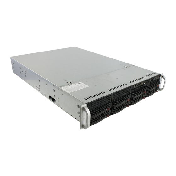
SUPERSERVER 6027R-TRF USER'S MANUAL Figure 6-1. Front and Rear Chassis Views 3.5" Drive Bays (2) USB Ports (2) COM Port Slim DVD-ROM Drive Control Panel SATA Drives (8) System Reset Main Power IPMI LAN Keyboard/Mouse Port 4 Standard Size PCI Slots... -
Page 65: System Fans
Chapter 6: Advanced Chassis Setup System Fans Three 8-cm hot-swap fans provide the cooling for the system. It is very important that the chassis top cover is properly installed and making a good seal in order for the cooling air to circulate properly through the chassis and cool the components. See Figure 6-2. -
Page 66: Replacing System Fans
SUPERSERVER 6027R-TRF USER'S MANUAL Replacing System Fans Removing a Fan 1. Remove the chassis cover. 2. Press the tabs on the sides of the fan to unlock and remove the fan and its housing. The fan's power connections will automatically detach. -
Page 67: Sata Drive Installation
Chapter 6: Advanced Chassis Setup SATA Drive Installation These drives are mounted in carriers to simplify their installation and removal from the chassis. The carriers also help promote proper airfl ow for the drives. For this reason, even empty carriers without hard drives installed must remain in the chassis. Mounting a SATA Drive in a Drive Carrier 1. -
Page 68: Hard Drive Backplane
SUPERSERVER 6027R-TRF USER'S MANUAL Figure 6-4. Removing a SAS/SATA Drive Carrier Handle Release Button Important: All of the drive carriers must remain in the drive bays to maintain proper cooling airfl ow. Hard Drive Backplane The hard drives plug into a backplane that provides power, drive ID and bus termination. -
Page 69: Dvd-Rom Installation
Chapter 6: Advanced Chassis Setup DVD-ROM Installation The top cover of the chassis must be opened to gain full access to the DVD-ROM drive bay. The 2022G-URF accomodates only slim type DVD-ROM drives. Side mounting brackets are typically needed to mount a slim DVD-ROM drive in the server. -
Page 70: Power Supply
SUPERSERVER 6027R-TRF USER'S MANUAL Power Supply The SUPERSERVER 6027R-TRF has a 740 Watt redundant power supply consisting of two power modules. Each power supply module has an auto-switching capability, which enables it to automatically sense and operate at a 100V - 240V input voltage. -
Page 71: Chapter 7 Bios
Chapter 7: BIOS Chapter 7 BIOS Introduction This chapter describes the AMI BIOS Setup Utility for the SUPERSERVER 6027R-TRF. The AMI ROM BIOS is stored in a Flash EEPROM and can be easily updated. This chapter describes the basic navigation of the AMI BIOS Setup Utility setup screens. -
Page 72: System Time/System Date
SUPERSERVER 6027R-TRF USER'S MANUAL System Time/System Date You can edit this fi eld to change the system time and date. Highlight System Time or System Date using the <Arrow> keys. Enter new values through the keyboard. Press the <Tab> key or the <Arrow> keys to move between fi elds. The date must be entered in DAY/MM/DD/YYYY format. - Page 73 Chapter 7: BIOS Power Confi guration Power Button Function If this feature is set to Instant Off, the system will power off immediately as soon as the user presses the power button. Select 4 Second Override for the system to power off when the user presses the power button for 4 seconds or longer. The options are Instant Off and 4 Seconds Override.
- Page 74 SUPERSERVER 6027R-TRF USER'S MANUAL • L1 Data Cache • L1 Code Cache • L2 Cache • L3 Cache Socket 1 CPU Information This item displays if a CPU is installed in Socket 1. CPU Speed This item displays the speed of the CPU installed in Socket 1.
- Page 75 Chapter 7: BIOS Hardware Prefetcher (Available when supported by the CPU) If set to Enabled, the hardware prefetcher will prefetch streams of data and instructions from the main memory to the L2 cache to improve CPU performance. The options are Disabled and Enabled. Adjacent Cache Line Prefetch (Available when supported by the CPU) If this feature is set to Disabled, The CPU prefetches the cache line for 64 bytes.
- Page 76 SUPERSERVER 6027R-TRF USER'S MANUAL Power Technology Select Energy Effi ciency to support power-saving mode. Select Custom to customize system power settings. Select Disabled to disable power -saving settings. The options are Disable, Energy Effi cient and Custom. If Custom is...
-
Page 77: North Bridge
Chapter 7: BIOS Factory Long Duration Maintained This item displays the period of time set by the manufacturer during which long duration power is maintained. Long Duration Maintained This item displays the period of time during which long duration power is maintained. - Page 78 SUPERSERVER 6027R-TRF USER'S MANUAL IOH 0 PCIe Port Bifurcation Control This submenu allows the user to confi gure the following 8 PCIe Port Bifurcation Control settings for the IOH 0 PCI-Exp port. This feature determines how to distribute the available PCI-Express lanes to the PCI-E Root Ports.
- Page 79 Chapter 7: BIOS IOH 1 PCIe Port Bifuracation Control This submenu allows the user to confi gure the following 6 PCIe Port Bifurcation Control settings for the IOH 1 PCI-Exp port. This feature determines how to distribute the available PCI-Express lanes to the PCI-E Root Ports. IOU1-PCIe Port This feature allows the user to set the PCI-Exp bus speed between IOU1 and PCI-e port.
- Page 80 SUPERSERVER 6027R-TRF USER'S MANUAL QPI (Quick Path Interconnect) Link Speed Mode Use this feature to select data transfer speed for QPI Link connections. The options are Fast and Slow. QPI Link Frequency Select Use this feature to select the desired QPI frequency. The options are Auto, 6.4 GT/s, 7.2 GT/s, and 8.0 GT/s.
- Page 81 Chapter 7: BIOS Perfmon and DFX Devices A PerfMon device monitors the activities of a remote system such as disk usage, memory consumption, and CPU load which will allow an IT administrator to maximize the performance of each computer within the network. A DFX device, usually in the form of a USB adaptor, can be used to enhance audio performance.
-
Page 82: South Bridge
SUPERSERVER 6027R-TRF USER'S MANUAL Demand Scrub Demand Scrubbing is a process that allows the CPU to correct correctable memory errors found on a memory module. When the CPU or I/O issues a demand-read command, and the read data from memory turns out to be a correctable error, the error is corrected and sent to the requestor (the original source). - Page 83 Chapter 7: BIOS All USB Devices Select Enabled to enable all onboard USB devices. The options are Enabled and Disabled. EHCI Controller 1/ EHCI Controller 2 Select Enabled to enable Enhanced Host Interface (EHCI) Controller 1 or Controller 2 to improve overall platform performance. The options are Enabled and Disabled.
- Page 84 SUPERSERVER 6027R-TRF USER'S MANUAL Serial-ATA (SATA) Controller 0~1 Use this feature to activate or dactivate the SATA controller, and set the com- patibility mode. The options for Controller 0 are Enhanced and Compatible. The default setting for SATA Controller 1 is Enhanced.
- Page 85 Chapter 7: BIOS SAS Confi guration If a SAS port is detected in the system, the following items will be displayed. SCU Devices Select Enabled to enable support for PCH SCU (System Confi guration Utility) devices. The options are Disabled and Enabled. OnChip SAS Oprom Select Enabled to support the onboard SAS Option ROM to boot up the system via a storage device if a SAS device is installed.The options are Disabled and Enabled.
- Page 86 SUPERSERVER 6027R-TRF USER'S MANUAL SERR# Generation Select Enabled to allow a PCI device to generate a SERR number for a PCI Bus Signal Error Event. The options are Enabled and Disabled. Maximum Payload This feature selects the setting for the PCIE maximum payload size. The options are Auto, 128 Bytes, 256 Bytes, 512 Bytes, 1024 Bytes, 2048 Bytes, and 4096 Bytes.
-
Page 87: Serial Port Console Redirection
Chapter 7: BIOS Super IO Confi guration (WPCM450) Super IO Chip Displays the Super IO chip type. Serial Port 0 Confi guration/Serial Port 1 Confi guration The submenus allow the user to confi gure the following settings for Serial Port 0 or Serial Port 1: Serial Port Select Enabled to enable a serial port specifi... -
Page 88: Console Redirection Settings
SUPERSERVER 6027R-TRF USER'S MANUAL Console Redirection Settings This feature allows the user to specify how the host computer will exchange data with the client computer, which is the remote computer used by the user. Terminal Type This feature allows the user to select the target terminal emulation type for Console Redirection. -
Page 89: Acpi Settings
Chapter 7: BIOS VT-UTF8 Combo Key Support Select Enabled to enable VT-UTF8 Combination Key support for ANSI/VT100 terminals. The options are Enabled and Disabled. Recorder Mode Select Enabled to capture the data displayed on a terminal and send it as text messages to a remote server. - Page 90 SUPERSERVER 6027R-TRF USER'S MANUAL Numa This feature enables the Non-Uniform Memory Access ACPI support. The options are Enabled and Disabled. High Precision Timer Select Enabled to activate the High Precision Event Timer (HPET) that produces periodic interrupts at a much higher frequency than a Real-time Clock (RTC) does...
-
Page 91: Event Logs
Chapter 7: BIOS ME (Management Engine) Subsystem Intel ME Subsystem Confi guration This feature displays the following ME Subsystem Confi guration settings. ME Subsystem Select Enabled to support Intel Management Engine (ME) Subsystem, a small power computer subsystem that performs various tasks in the background. The options are Enabled and Disabled. -
Page 92: Ipmi
SUPERSERVER 6027R-TRF USER'S MANUAL Smbios Event Log Standard Settings Log System Boot Event This option toggles the System Boot Event logging to enabled or disabled. The options are Disabled and Enabled. MECI The Multiple Event Count Increment (MECI) counter counts the number of occurences a duplicate event must happen before the MECI counter is incremented. - Page 93 Chapter 7: BIOS When SEL is Full This feature allows the user to decide what the BIOS should do when the system event log is full. Select Erase Immediately to erase all events in the log when the system event log is full. The options are Do Nothing and Erase Immediately. Cstom EFI Logging Options Log EFI Status Codes Select Enabled to log EFI (Extensible Firmware Interface) Status...
-
Page 94: Boot
SUPERSERVER 6027R-TRF USER'S MANUAL Router IP Address This item displays the Router IP address for this computer. This should be in decimal and in dotted quad form (i.e., 192.168.10.253). Router MAC Address This item displays the Router Mac address for this computer. Mac addresses are 6 two-digit hexadecimal numbers. -
Page 95: Save & Exit
Chapter 7: BIOS Save & Exit This menu allows the user to confi gure the Save and Exit settings for the system. Discard Changes and Exit Select this option to quit the BIOS Setup without making any permanent changes to the system confi guration, and reboot the computer. Select Discard Changes and Exit, and press <Enter>. - Page 96 SUPERSERVER 6027R-TRF USER'S MANUAL Restore User Defaults Select this feature and press <Enter> to load the user's defaults previously saved in the system. When the dialog box appears, asking you if you want to restore user's defaults, click Yes to restore the user's defaults previously saved in the system, or click No to abandon the user's defaults that were previously saved.
-
Page 97: Appendix A Bios Error Beep Codes
Appendix A: BIOS Error Beep Codes Appendix A BIOS Error Beep Codes During the POST (Power-On Self-Test) routines, which are performed each time the system is powered on, errors may occur. Non-fatal errors are those which, in most cases, allow the system to continue the boot-up process. - Page 98 SUPERSERVER 6027R-TRF USER'S MANUAL Notes...
-
Page 99: Appendix B System Specifi Cations
Appendix B: System Specifi cations Appendix B System Specifi cations Processors Dual Intel E5-2600 Series series (Socket R LGA2011 type) processors Note: You must install at least two processors for full functions to be supported. Note: Please refer to our web site for a complete listing of supported processors. Chipset One Intel PCH C602 chipset and one Intel PCH C606 Southbridge chipset BIOS... - Page 100 SUPERSERVER 6027R-TRF USER'S MANUAL Serverboard X9DRi-F (ATX form factor) Dimensions: 12.00" (L) x 13.00" (W) (304.80 mm x 330.20 mm) Chassis SC825TS-R740LPBP (2U rackmount) Dimensions: (WxHxD) 16.8 x 3.5 x 25.5 in. (427 x 89 x 648 mm) Weight Gross (Bare Bone): 57 lbs. (25.9 kg.)
- Page 101 Appendix B: System Specifi cations Regulatory Compliance Electromagnetic Emissions: FCC Class A, EN 55022 Class A, EN 61000-3-2/- 3-3, CISPR 22 Class A Electromagnetic Immunity: EN 55024/CISPR 24, (EN 61000-4-2, EN 61000-4-3, EN 61000-4-4, EN 61000-4-5, EN 61000-4-6, EN 61000-4-8, EN 61000-4-11) Safety: CSA/EN/IEC/UL 60950-1 Compliant, UL or CSA Listed (USA and Canada), CE Marking (Europe) California Best Management Practices Regulations for Perchlorate Materials:...
- Page 102 SUPERSERVER 6027R-TRF USER'S MANUAL (continued from front) The products sold by Supermicro are not intended for and will not be used in life support systems, medical equipment, nuclear facilities or systems, aircraft, aircraft devices, aircraft/emergency communication devices or other critical systems whose failure to perform be reasonably expected to result in signifi...
Need help?
Do you have a question about the SUPERSERVER 6027R-TRF and is the answer not in the manual?
Questions and answers