Table of Contents
Advertisement
Quick Links
Advertisement
Table of Contents

Related Manuals for Supero SUPERSERVER 6025W-NTR+


Summary of Contents for Supero SUPERSERVER 6025W-NTR+
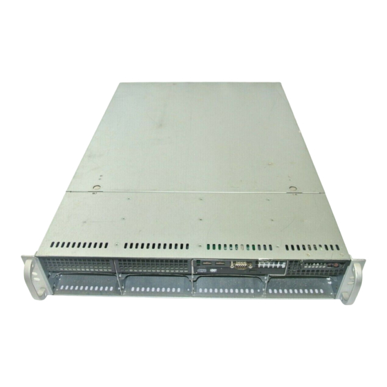
- Page 1 UPER ® 6025W-NTR+ UPER ERVER USER’S MANUAL 1.0a...
- Page 2 Please Note: For the most up-to-date version of this manual, please see our web site at www.supermicro.com. Super Micro Computer, Inc. ("Supermicro") reserves the right to make changes to the product described in this manual at any time and without notice. This product, including software, if any, and documentation may not, in whole or in part, be copied, photocopied, reproduced, translated or reduced to any medium or machine without prior written consent.
-
Page 3: About This Manual
Preface Preface About This Manual This manual is written for professional system integrators and PC technicians. It provides information for the installation and use of the SuperServer 6025W-NTR+. Installation and maintainance should be performed by experienced technicians only. The SuperServer 6025W-NTR+ is a high-end server based on the SC825TQ- R700LP 2U rackmount chassis and the X7DWN+, a dual processor serverboard that ®... - Page 4 UPER ERVER 6025W-NTR+ User's Manual Chapter 5: Advanced Serverboard Setup Chapter 5 provides detailed information on the X7DWN+ serverboard, including the locations and functions of connections, headers and jumpers. Refer to this chapter when adding or removing processors or main memory and when reconfi guring the serverboard.
-
Page 5: Table Of Contents
Serial ATA Subsystem ..................1-3 Front Control Panel ..................1-4 I/O Backplane ....................1-4 Cooling System ....................1-4 Contacting Supermicro ..................1-6 Chapter 2 Server Installation 2-1 Overview ......................2-1 Unpacking the System ..................2-1 Preparing for Setup ..................2-1 Choosing a Setup Location ................ - Page 6 UPER ERVER 6025W-NTR+ User's Manual Installing the Server into a Telco Rack ............2-6 Checking the Serverboard Setup ..............2-8 Checking the Drive Bay Setup ..............2-10 Chapter 3 System Interface Overview ......................3-1 Control Panel Buttons ..................3-1 Reset ....................... 3-1 Power ......................
- Page 7 Table of Contents 5-11 Onboard Indicators ..................5-23 5-12 Floppy, IDE, and SATA Ports ................ 5-24 Chapter 6 Advanced Chassis Setup Static-Sensitive Devices .................. 6-1 Precautions ..................... 6-1 Unpacking ....................... 6-1 Control Panel ....................6-2 System Fans ....................6-3 System Fan Failure ..................6-3 Replacing System Fans ..................
- Page 8 UPER ERVER 6025W-NTR+ User's Manual Notes viii...
-
Page 9: Chapter 1 Introduction
Intel® Xeon® processor serverboard. Please refer to our web site for information on operating systems that have been certifi ed for use with the SuperServer 6025W- NTR+ (www.supermicro.com). In addition to the serverboard and chassis, various hardware components have been included with the SuperServer 6025W-NTR+, as listed below: •... -
Page 10: Serverboard Features
(in a x8 slot), two 64-bit 133/100 MHz PCI-X slots and one UIO slot (see below). The X7DWN+ is a specially-designed serverboard that features Supermicro's UIO (Universal I/O) technology. UIO serverboards have a PCI-Express x8 connector that can support any one of several types of UIO card types (low-profi le only) to... -
Page 11: Onboard Controllers/Ports
Chapter 1: Introduction to tailor the serverboard to their own needs. Note: the 6025W-NTR+ does not come with a UIO card pre-installed. Onboard Controllers/Ports One fl oppy drive connector and two onboard ATA/100 connectors (one reserved for the use of a compact fl ash card) are provided to support IDE hard drives or ATAPI devices. -
Page 12: Front Control Panel
UPER ERVER 6025W-NTR+ User's Manual Front Control Panel The control panel on the SuperServer 6025W-NTR+ provides you with system monitoring and control. LEDs indicate system power, HDD activity, network activity, system overheat and power supply failure. A main power button and a system reset button are also included. - Page 13 Chapter 1: Introduction Figure 1-1. Intel 5400/ESB2 Chipset: System Block Diagram Note: This is a general block diagram. Please see Chapter 5 for details.
-
Page 14: Contacting Supermicro
Super Micro Computer, Inc. 980 Rock Ave. San Jose, CA 95131 U.S.A. Tel: +1 (408) 503-8000 Fax: +1 (408) 503-8008 Email: marketing@supermicro.com (General Information) support@supermicro.com (Technical Support) Web Site: www.supermicro.com Europe Address: Super Micro Computer B.V. Het Sterrenbeeld 28, 5215 ML... -
Page 15: Chapter 2 Server Installation
Chapter 2: Server Installation Chapter 2 Server Installation 2-1 Overview This chapter provides a quick setup checklist to get your SuperServer 6025W-NTR+ up and running. Following these steps in the order given should enable you to have the system operational within a minimum amount of time. This quick setup assumes that your system has come to you with the processors and memory preinstalled. -
Page 16: Rack Precautions
UPER ERVER 6025W-NTR+ User's Manual • This product is for installation only in a Restricted Access Location (dedicated equipment rooms, service closets and the like). • This product is not suitable for use with visual display work place devices acccording to §2 of the the German Ordinance for Work with Visual Display Units. -
Page 17: Rack Mounting Considerations
Chapter 2: Server Installation Rack Mounting Considerations Ambient Operating Temperature If installed in a closed or multi-unit rack assembly, the ambient operating tempera- ture of the rack environment may be greater than the ambient temperature of the room. Therefore, consideration should be given to installing the equipment in an environment compatible with the manufacturer’s maximum rated ambient tempera- ture (Tmra). -
Page 18: Installing The System Into A Rack
UPER ERVER 6025W-NTR+ User's Manual Installing the System into a Rack This section provides information on installing the SuperServer 6025W-NTR+ into a rack unit. If the 6025W-NTR+ has already been mounted into a rack, you can skip ahead to Sections 2-5 and 2-6. There are a variety of rack units on the market, which may mean the assembly procedure will differ slightly. - Page 19 Chapter 2: Server Installation Figure 2-1. Installing Chassis Rails...
-
Page 20: Installing The Rack Rails
UPER ERVER 6025W-NTR+ User's Manual Installing the Rack Rails: Determine where you want to place the SuperServer 6025W-NTR+ in the rack. (See Rack and Server Precautions in Section 2-3.) Position the fi xed rack rail/sliding rail guide assemblies (made up of two inter-locking sections) at the desired location in the rack, keeping the sliding rail guide facing the inside of the rack and the rollers toward the front of the rack. - Page 21 Chapter 2: Server Installation Figure 2-2. Installing the Server into a Rack...
-
Page 22: Checking The Serverboard Setup
UPER ERVER 6025W-NTR+ User's Manual Checking the Serverboard Setup After you install the 6025W-NTR+ in the rack, you will need to open the unit to make sure the serverboard is properly installed and all the connections have been made. Accessing the inside of the System First, grasp the two handles on either side and pull the unit straight out until it locks (you will hear a "click"). - Page 23 Chapter 2: Server Installation Figure 2-3. Accessing the Inside of the System...
-
Page 24: Checking The Drive Bay Setup
UPER ERVER 6025W-NTR+ User's Manual Checking the Drive Bay Setup Next, you should check to make sure the peripheral drives and the Serial ATA drives have been properly installed and all connections have been made. Checking the Drives All drives are accessable from the front of the server. For servicing the DVD- ROM and fl... -
Page 25: Chapter 3 System Interface
Chapter 3: System Interface Chapter 3 System Interface Overview There are several LEDs on the control panel as well as others on the Serial ATA drive carriers to keep you constantly informed of the overall status of the system as well as the activity and health of specifi... -
Page 26: Control Panel Leds
SUPERSERVER 6025W-NTR+ User's Manual Control Panel LEDs The control panel located on the front of the chassis has several LEDs. These LEDs provide you with critical information related to different parts of the system. This section explains what each LED indicates when illuminated and any corrective action you may need to take. -
Page 27: Hdd
Chapter 3: System Interface Indicates IDE channel activity. On the SuperServer 6025W-NTR+, this LED indicates SATA and/or DVD-ROM drive activity when fl ashing. Power Indicates power is being supplied to the system's power supply units. This LED should normally be illuminated when the system is operating. Drive Carrier LEDs SATA Drives Each SATA drive carrier has two LEDs:... - Page 28 SUPERSERVER 6025W-NTR+ User's Manual Notes...
-
Page 29: Chapter 4 System Safety
Chapter 4: System Safety Chapter 4 System Safety Electrical Safety Precautions Basic electrical safety precautions should be followed to protect yourself from harm and the SuperServer 6025W-NTR+ from damage: • Be aware of the locations of the power on/off switch on the chassis as well as the room's emergency power-off switch, disconnection switch or electrical outlet. -
Page 30: General Safety Precautions
UPER ERVER 6025W-NTR+ User's Manual • Serverboard Battery: CAUTION - There is a danger of explosion if the onboard battery is installed upside down, which will reverse its polarites (see Figure 4-1). This battery must be replaced only with the same or an equivalent type recommended by the manufacturer. -
Page 31: Esd Precautions
Chapter 4: System Safety • After accessing the inside of the system, close the system back up and secure it to the rack unit with the retention screws after ensuring that all connections have been made. ESD Precautions Electrostatic discharge (ESD) is generated by two objects with different electrical charges coming into contact with each other. -
Page 32: Operating Precautions
UPER ERVER 6025W-NTR+ User's Manual Operating Precautions Care must be taken to assure that the chassis cover is in place when the 6025W- NTR+ is operating to assure proper cooling. Out of warranty damage to the system can occur if this practice is not strictly followed. Figure 4-1. -
Page 33: Chapter 5 Advanced Serverboard Setup
Chapter 5: Advanced Serverboard Setup Chapter 5 Advanced Serverboard Setup This chapter covers the steps required to install the X7DWN+ serverboard into the chassis, connect the data and power cables and install add-on cards. All serverboard jumpers and connections are also described. A layout and quick refer- ence chart are included in this chapter for your reference. -
Page 34: Unpacking
The X7DWN+ requires a chassis big enough to support a 13.68" x 13.05" serverboard, such as Supermicro's SC825TQ-R700LP. Make sure that the I/O ports on the serverboard align properly with their respective holes in the I/O shield at the back of the chassis. -
Page 35: Connecting Cables
Chapter 5: Advanced Serverboard Setup Connecting Cables Now that the serverboard is installed, the next step is to connect the cables to the board. These include the data cables for the peripherals and control panel and the power cables. Connecting Data Cables The cables used to transfer data from the peripheral devices have been carefully routed to prevent them from blocking the fl... -
Page 36: I/O Ports
UPER ERVER 6025W-NTR+ User's Manual Figure 5-1. Control Panel Header Pins Ground x (Key) x (Key) Power On LED HDD LED NIC1 LED NIC2 LED OH/Fan Fail LED Power Fail LED Ground Reset (Button) Ground Power (Button) I/O Ports The I/O ports are color coded in conformance with the PC 99 specifi cation. See Figure 5-2 below for the colors and locations of the various I/O ports. -
Page 37: Installing The Processors And Heat Sinks
Chapter 5: Advanced Serverboard Setup Installing the Processors and Heat Sinks Avoid placing direct pressure to the top of the processor package. Always remove the power cord fi rst before adding, removing or changing any hardware components. Notes: Always connect the power cord last and remove it before adding, remov- ing or changing any components. - Page 38 UPER ERVER 6025W-NTR+ User's Manual CPU Installation A black PnP cap is attached to the load plate to protect the CPU socket. Press the load lever down and away from the retention clasp Load lever to release the load plate from its PnP cap locked position.
- Page 39 Chapter 5: Advanced Serverboard Setup With the CPU in the socket, in- Gold dot spect the four corners of the CPU Socket key to make sure that it is properly installed. CPU key Use your thumb to gently push the load lever down until it snaps into the retention clasp.
- Page 40 UPER ERVER 6025W-NTR+ User's Manual Installation and Removal of the Heat Sink CPU Heat Sink Installation Do not apply any thermal grease to the heat sink or the CPU die; the required amount has already been applied. Screw #1 Place the heatsink on top of the CPU so that the four mounting holes are aligned with those on the retention mechanism.
-
Page 41: Memory Support
Chapter 5: Advanced Serverboard Setup Installing Memory CAUTION! Exercise extreme care when installing or removing DIMM modules to prevent any possible damage. Memory Support The X7DWN+ supports up to 128 GB fully buffered (FBD) ECC DDR2 800/667/533 in 16 DIMM slots (four channels, two branches)*. Both 1.5V and 1.8V memory are supported. -
Page 42: Adding Pci Add-On Cards
UPER ERVER 6025W-NTR+ User's Manual Figure 5-3. DIMM Installation DDR2 FBD DIMM To Install: Insert module vertically and press down until it snaps into place. Pay attention to the bottom notches. To Remove: Use your thumbs to gently push each release tab outward to free the DIMM from the slot. -
Page 43: Serverboard Details
Chapter 5: Advanced Serverboard Setup Serverboard Details Figure 5-4. X7DWN+ Layout (not drawn to scale) 5-11... -
Page 44: X7Dwn+ Quick Reference
UPER ERVER 6025W-NTR+ User's Manual X7DWN+ Quick Reference Jumper Description Default Setting 3rd Power Fail Detect Open (Disabled) JBT1 CMOS Clear (See Section 5-10) JCF1 Compact Flash Card Master/Slave Closed (Master) C1/JI C to PCI-X/PCI-E Slots Open (Disabled) Reboot Option Open (Reboot) Memory Voltage Select Pins 1-2 (Auto) -
Page 45: Connector Defi Nitions
Chapter 5: Advanced Serverboard Setup Connector Defi nitions ATX Power 24-pin Connector Pin Defi nitions (JPW1) Pin# Defi nition Pin # Defi nition Main ATX Power Supply +3.3V +3.3V Connector -12V +3.3V The primary power supply connector (JPW1) meets the SSI (Superset ATX) PS_ON 24-pin specifi... - Page 46 UPER ERVER 6025W-NTR+ User's Manual Power Fail LED PWR Fail LED The Power Fail LED connection is Pin Defi nitions (JF1) located on pins 5 and 6 of JF1. Re- Pin# Defi nition fer to the table on the right for pin defi...
- Page 47 Chapter 5: Advanced Serverboard Setup Power On LED Power LED Pin Defi nitions (JF1) The Power On LED connector is lo- Pin# Defi nition cated on pins 15 and 16 of JF1 (use 5V Stby JLED for a 3-pin connector). This Control connection is used to provide LED indication of power being supplied to...
- Page 48 Signal: Alarm Reset chassis. See the table on the right for Note: This feature is only available when us- pin defi nitions. ing Supermicro redundant power supplies. LAN1/2 (Ethernet Ports) Two Ethernet ports (designated LAN1 and LAN2) are located beside the VGA port on the I/O backplane.
- Page 49 Chapter 5: Advanced Serverboard Setup Serial Ports Serial Port Pin Defi nitions (COM1/COM2) Two serial ports are included on the Pin # Defi nition Pin # Defi nition serverboard. COM1 is a backpanel port and COM2 is a header located near the JWOL header.
- Page 50 UPER ERVER 6025W-NTR+ User's Manual Alarm Reset If three power supplies are installed, the system can notify you when any of Alarm Reset Header Pin Defi nitions (JAR) the three power modules fail. Connect Pin Setting Defi nition JAR to a micro-switch to enable you Pin 1 Ground to turn off the alarm that is activated...
-
Page 51: 5-10 Jumper Settings
Chapter 5: Advanced Serverboard Setup Keylock Keylock Pin Defi nitions (JK1) The keyboard lock connection is designated Pin# Defi nition JK1. Utilizing this header allows you to inhibit Ground any actions made on the keyboard, effectively Keylock R-N "locking" it. Compact Flash Card PWR Connector Compact Flash Card PWR... - Page 52 UPER ERVER 6025W-NTR+ User's Manual CMOS Clear JBT1 is used to clear CMOS (which will also clear any passwords). Instead of pins, this jumper consists of contact pads to prevent accidentally clearing the contents of CMOS. To clear CMOS, First power down the system and unplug the power cord(s). With the power disconnected, short the CMOS pads with a metal object such as a small screwdriver.
- Page 53 Chapter 5: Advanced Serverboard Setup Watch Dog Enable/Disable Watch Dog JWD controls the Watch Dog function. Jumper Settings (JWD) Watch Dog is a system monitor that Jumper Setting Defi nition can reboot the system when a software Pins 1-2 Reset application hangs.
- Page 54 UPER ERVER 6025W-NTR+ User's Manual Reboot Option Reboot Option Setting jumper JP1 to Open (the default Jumper Settings (JP1) setting) will allow the system to automati- Setting Defi nition cally reboot after power-off. See the table Reboot on the right for jumper settings. No Reboot Memory Voltage Select Memory Voltage Select...
-
Page 55: 5-11 Onboard Indicators
Chapter 5: Advanced Serverboard Setup 5-11 Onboard Indicators GLAN1/2 LED (Connection Speed Indicator) LED Color Defi nition LAN1/2 LEDs 10 MHz The Ethernet ports (located beside Green 100 MHz the VGA port) have two LEDs. On Amber 1 GHz each port, one LED indicates activity while the other LED may be green, amber or off to indicate the speed of the connection. -
Page 56: 5-12 Floppy, Ide, And Sata Ports
UPER ERVER 6025W-NTR+ User's Manual 5-12 Floppy, IDE, and SATA Ports Use the following information to connect the IDE hard disk drive cables. • A red mark on a wire typically designates the location of pin 1. • The 80-wire ATA100/66 IDE hard disk drive cable that came with your system has two connectors to support two drives. - Page 57 Chapter 5: Advanced Serverboard Setup IDE Connectors IDE Drive Connector Pin Defi nitions (IDE#1) There are two IDE connectors (one Pin# Defi nition Pin # Defi nition blue and one white) on the serverboard. Reset IDE Ground IDE#1 (blue) is designated as the Pri- Host Data 7 Host Data 8 mary IDE drive.
- Page 58 UPER ERVER 6025W-NTR+ User's Manual Notes 5-26...
-
Page 59: Chapter 6 Advanced Chassis Setup
Chapter 6: Advanced Chassis Setup Chapter 6 Advanced Chassis Setup This chapter covers the steps required to install components and perform main- tenance on the SC825TQ-R700LP chassis. For component installation, follow the steps in the order given to eliminate the most common problems encountered. If some steps are unnecessary, skip ahead to the step that follows. -
Page 60: Control Panel
UPER ERVER 6025W-NTR+ User's Manual Figure 6-1. Front and Rear Chassis Views 3.5" Drive Bays (2) Slim DVD-ROM Drive USB Ports (2), COM Port Control Panel SATA Drives (8) Floppy Drive (optional) System Reset Main Power Keyboard/Mouse Ports Parallel Port 7 Low-Profi... -
Page 61: System Fans
Installing a new fan Replace the failed fan with an identical 8-cm, 12 volt fan (available from Supermicro, p/n FAN-0070). Position the new fan into the space vacated by the failed fan previously re- moved. A "click" can be heard when the fan is fully installed in place and the power connections are made. -
Page 62: Drive Bay Installation/Removal
UPER ERVER 6025W-NTR+ User's Manual Figure 6-2. Removing System Cooling Fans Drive Bay Installation/Removal Accessing the Drive Bays SATA Drives: You do not need to access the inside of the chassis or remove power to replace or swap SATA drives. Proceed to the next step for instructions. Note: You must use standard 1"... -
Page 63: Sata Drive Installation
Chapter 6: Advanced Chassis Setup SATA Drive Installation The SATA drives are mounted in drive carriers to simplify their installation and removal from the chassis. These carriers also help promote proper airfl ow for the drives. For this reason, even empty carriers without SATA drives installed must remain in the chassis. -
Page 64: Hard Drive Backplane
UPER ERVER 6025W-NTR+ User's Manual Figure 6-4. Removing a Serial ATA Drive Carrier Handle Release Button Important: All of the SATA drive carriers must remain in the drive bays to maintain proper cooling airfl ow. Hard Drive Backplane The SATA drives plug into a backplane that provides power, drive ID and bus termi- nation. -
Page 65: Dvd-Rom And Floppy Drive Installation
Chapter 6: Advanced Chassis Setup DVD-ROM and Floppy Drive Installation The top cover of the chassis must be opened to gain full access to the DVD-ROM and fl oppy drive bays. The 6025W-NTR+ accomodates only slim type DVD-ROM drives. Side mounting brakets are typically needed to mount a slim DVD-ROM drive in the 6025W-NTR+ server. -
Page 66: Power Supply
The PWR Fail LED will illuminate and remain on until the failed unit has been replaced. Replace- ment units can be ordered directly from Supermicro (see contact information in the Preface). The power supply units have a hot-swap capability, meaning you can replace the failed unit without powering down the system. -
Page 67: Chapter 7Bios
Note: Due to periodic changes to the BIOS, some settings may have been added or deleted and might not yet be recorded in this manual. Please refer to the Manual Download area of the Supermicro web site <http://www.supermicro.com> for any changes to the BIOS that may not be refl ected in this manual. -
Page 68: Running Setup
UPER ERVER 6025W-NTR+ User's Manual Running Setup Default settings are in bold text unless otherwise noted. The BIOS setup options described in this section are selected by choosing the appropriate text from the main BIOS Setup screen. All displayed text is described in this section, although the screen display is often all you need to understand how to set the options as shown on the following page. -
Page 69: Main Bios Setup Menu
Chapter 7: BIOS Main BIOS Setup Menu Main Setup Features System Time To set the system date and time, key in the correct information in the appropriate fi elds. Then press the <Enter> key to save the data. System Date Using the arrow keys, highlight the month, day and year fi... - Page 70 UPER ERVER 6025W-NTR+ User's Manual Type This option allows the user to select the type of IDE hard drive. Select Auto to allow the BIOS to automatically confi gure the parameters of the HDD installed at the connection. Enter a number between 1 to 39 to select a predetermined HDD type.
- Page 71 Chapter 7: BIOS SATA Controller Mode Option Select Compatible to allow the SATA and PATA drives to be automatically-detected and be placed in the Legacy Mode by the BIOS. Select Enhanced to allow the SATA and PATA drives to be to be automatically-detected and be placed in the Native IDE Mode.
-
Page 72: Advanced Setup
UPER ERVER 6025W-NTR+ User's Manual Advanced Setup Choose Advanced from the Phoenix BIOS Setup Utility main menu with the arrow keys. You should see the following display. The items with a triangle beside them have sub menus that can be accessed by highlighting the item and pressing <Enter>. Boot Features Access the submenu to make changes to the following settings. - Page 73 Chapter 7: BIOS Power Button Behavior If set to Instant-Off, the system will power off immediately as soon as the user hits the power button. If set to 4-sec., the system will power off when the user presses the power button for 4 seconds or longer. The options are instant-off and 4-sec override.
- Page 74 UPER ERVER 6025W-NTR+ User's Manual Memory Cache Cache System BIOS Area This setting allows you to designate a reserve area in the system memory to be used as a System BIOS buffer to allow the BIOS to write (cache) its data into this reserved memory area.
- Page 75 Chapter 7: BIOS be cached (written) into a buffer, a storage area in the Static DROM (SDROM) or written into L1, L2, L3 cache inside the CPU to speed up CPU operations. Select Uncached to disable this function. Select Write Through to allow data to be cached into the buffer and written into the system memory at the same time.
- Page 76 UPER ERVER 6025W-NTR+ User's Manual PCI Parity Error Forwarding Enable this item to forward the PCI errors occurring behind P2P bridges to the South Bridge, so NMI can be asserted. The options are Enabled and Disabled. PCI Fast Delayed Transaction Enable this function to improve the DMA data transfer rate for a PCI 32-bit multimedia card.
-
Page 77: Advanced Chipset Control
Chapter 7: BIOS DOS or Other (for Unix, Novelle NetWare and other operating systems). Advanced Chipset Control Access the submenu to make changes to the following settings. Warning : Take caution when changing the Advanced settings. An Incor- rect value, a very high DRAM frequency or an incorrect DRAM timing may cause system to become unstable. - Page 78 UPER ERVER 6025W-NTR+ User's Manual Memory Voltage Select Auto to allow the BIOS to automatically detect memory voltage based on the SPD table. Select 1.5V to force the system to use 1.5V for lower power fully- buffered DIMM modules. Select 1.8V to use 1.8V power for onboard memory modules.
- Page 79 Chapter 7: BIOS AMB Thermal Sensor Select Enabled to enable the thermal sensor embedded in the Advanced Memory Buffer on a fully buffered memory module for thermal monitoring. The options are Disabled and Enabled. Thermal Throttle Select Enabled to enable closed-loop thermal throttling on a fully buffered (FBD) memory module.
-
Page 80: Advanced Processor Options
UPER ERVER 6025W-NTR+ User's Manual High Precision Event Time Select Yes to activate the High Precision Event Timer (HPET), which is capable of producing periodic interrupts at a much higher frequency than a Real-time Clock (RTC) can in synchronizing multimedia streams, providing smooth playback and reducing the dependency on other timestamp calculation devices, such as an x86 RDTSC Instruction embedded in a CPU. - Page 81 Chapter 7: BIOS C1/C2 Enhanced Mode (Available when supported by the CPU.) Set to Enabled to enable Enhanced Halt State to lower CPU voltage/frequency to prevent overheat. The options are Enabled and Disabled. (Note: please refer to Intel’s web site for detailed information.) Execute Disable Bit (Available when supported by the CPU and the OS.) Set to Enabled to enable Execute Disable Bit and allow the processor to classify areas in memory where an application code can execute and where it cannot, and...
- Page 82 UPER ERVER 6025W-NTR+ User's Manual multiple "virtual" systems in one physical computer. The options are Enabled and Disabled. (Note: If there is any change to this setting, you will need to power off and restart the system for the change to take effect.) Please refer to Intel’s web site for detailed information.
- Page 83 Chapter 7: BIOS Mode This setting allows you to set the type of device that will be connected to serial port B. The options are Normal and IR (for an infrared device). Base I/O Address This setting allows you to select the base I/O address for serial port B. The options are 3F8, 2F8, 3E8 and 2E8.
-
Page 84: Dmi Event Logging
UPER ERVER 6025W-NTR+ User's Manual DMI Event Logging Access the submenu to make changes to the following settings. Event Log Validity This is a display to inform you of the event log validity. It is not a setting. Event Log Capacity This is a display to inform you of the event log capacity. -
Page 85: Console Redirection
Chapter 7: BIOS Console Redirection Access the submenu to make changes to the following settings. COM Port Address This item allows you to specify which COM port to direct the remote console to: Onboard COM A or Onboard COM B. This setting can also be Disabled. BAUD Rate This item allows you to set the BAUD rate for console redirection. -
Page 86: Hardware Monitor Logic
UPER ERVER 6025W-NTR+ User's Manual Hardware Monitor Logic Highlight this and hit <Enter> to see the status for the following items: CPU1 Temperature/CPU2 Temperature/System Temperature Fan1-Fan8 Speeds: If the feature of Auto Fan Control is enabled, the BIOS will automatically display the status of the fans indicated in this item. - Page 87 Chapter 7: BIOS IPMI (The option is available only when an IPMI card is installed in the system.) IPMI Specifi cation Version: This item displays the current IPMI Version. Firmware Version: This item displays the current Firmware Version. System Event Logging Select Enabled to enable IPMI Event Logging.
- Page 88 UPER ERVER 6025W-NTR+ User's Manual BIOS POST Watch Dog Set to Enabled to enable POST Watch Dog. The options are Enabled and Dis- abled. OS Boot Watch Dog Set to Enabled to enable OS Boot Watch Dog. The options are Enabled and Dis- abled.
-
Page 89: Realtime Sensor Data
Chapter 7: BIOS Realtime Sensor Data This feature display information from motherboard sensors, such as temperatures, fan speeds and voltages of various components. The following items will also appear: IP Address, IP Subnet Mask, Default Gateway, MAC Address Byte0, MAC Address Byte1, MAC Address Byte2, MAC Address Byte3, MAC Address Byte4,... - Page 90 UPER ERVER 6025W-NTR+ User's Manual IPMI LAN Confi guration The following features allow the user to confi gure and monitor IPMI LAN settings. VLAN Tagging Select Enabled to enable Virtual LAN(s) for IPMI connections and allow the user to confi gure VLAN settings. The options are Enabled and Disabled. VLAN ID If VLAN Tagging above is set to Enabled, this item allows the user to change the VLAN ID.
-
Page 91: Security
Chapter 7: BIOS Security Choose Security from the Phoenix BIOS Setup Utility main menu with the arrow keys. You should see the following display. Security setting options are displayed by highlighting the setting using the arrow keys and pressing <Enter>. All Security BIOS settings are described in this section. -
Page 92: Boot
UPER ERVER 6025W-NTR+ User's Manual Boot Choose Boot from the Phoenix BIOS Setup Utility main menu with the arrow keys. You should see the following display. See details on how to change the order and specs of boot devices in the Item Specifi c Help window. All Boot BIOS settings are described in this section. -
Page 93: Exit
Chapter 7: BIOS Exit Choose Exit from the Phoenix BIOS Setup Utility main menu with the arrow keys. You should see the following display. All Exit BIOS settings are described in this section. Exit Saving Changes Highlight this item and hit <Enter> to save any changes you made and to exit the BIOS Setup utility. - Page 94 UPER ERVER 6025W-NTR+ User's Manual Notes 7-28...
-
Page 95: Appendix A Bios Post Messages
Appendix A: BIOS POST Messages Appendix A BIOS POST Messages During the Power-On Self-Test (POST), the BIOS will check for problems. If a problem is found, the BIOS will activate an alarm or display a message. The fol- lowing is a list of such BIOS messages. Failure Fixed Disk Fixed disk is not working or not confi... - Page 96 UPER ERVER 6025W-NTR+ User's Manual System CMOS checksum bad - Default confi guration used System CMOS has been corrupted or modifi ed incorrectly, perhaps by an applica- tion program that changes data stored in CMOS. The BIOS installed Default Setup Values.
- Page 97 Appendix A: BIOS POST Messages System cache error - Cache disabled RAM cache failed and BIOS disabled the cache. On older boards, check the cache jumpers. You may have to replace the cache. See your dealer. A disabled cache slows system performance considerably. CPU ID: CPU socket number for Multi-Processor error.
- Page 98 UPER ERVER 6025W-NTR+ User's Manual Invalid System Confi guration Data Problem with NVRAM (CMOS) data. I/O device IRQ confl ict I/O device IRQ confl ict error. PS/2 Mouse Boot Summary Screen: PS/2 Mouse installed. nnnn kB Extended RAM Passed Where nnnn is the amount of RAM in kilobytes successfully tested. nnnn Cache SRAM Passed Where nnnn is the amount of system cache in kilobytes successfully tested.
- Page 99 Appendix A: BIOS POST Messages Press <F1> to resume, <F2> to Setup, <F3> for previous Displayed after any recoverable error message. Press <F1> to start the boot process or <F2> to enter Setup and change the settings. Press <F3> to display the previous screen (usually an initialization error of an Option ROM, i.e., an add-on card).
- Page 100 UPER ERVER 6025W-NTR+ User's Manual Notes...
-
Page 101: Appendix B Bios Post Codes
Appendix B: BIOS POST Codes Appendix B BIOS POST Codes This section lists the POST (Power On Self Test) codes for the Phoenix BIOS. POST codes are divided into two categories: recoverable and terminal. Recoverable POST Errors When a recoverable type of error occurs during POST, the BIOS will display an POST code that describes the problem. - Page 102 UPER ERVER 6025W-NTR+ User's Manual POST Code Description 8254 timer initialization 8237 DMA controller initialization Reset Programmable Interrupt Controller 1-3-1-1 Test DRAM refresh 1-3-1-3 Test 8742 Keyboard Controller Set ES segment register to 4 GB Auto size DRAM Initialize POST Memory Manager Clear 512 kB base RAM 1-3-4-1 RAM failure on address line xxxx* 1-3-4-3 RAM failure on data bits xxxx* of low byte of memory...
- Page 103 Appendix B: BIOS POST Codes POST Code Description Test RAM between 512 and 640 kB Test extended memory Test extended memory address lines Jump to UserPatch1 Confi gure advanced cache registers Initialize Multi Processor APIC Enable external and CPU caches Setup System Management Mode (SMM) area Display external L2 cache size Load custom defaults (optional)
- Page 104 UPER ERVER 6025W-NTR+ User's Manual POST Code Description Check for SMART Drive (optional) Set up Power Management Initialize security engine (optional) Enable hardware interrupts Determine number of ATA and SCSI drives Set time of day Check key lock Initialize typematic rate Erase <ESC>...
- Page 105 Appendix B: BIOS POST Codes POST Code Description Unknown interrupt Check Intel Branding string Alert Standard Format initialization Late init for IPMI Log error if micro-code not updated properly The following are for boot block in Flash ROM POST Code Description Initialize the chipset Initialize the bridge Initialize the CPU...
- Page 106 UPER ERVER 6025W-NTR+ User's Manual Notes...
-
Page 107: Appendix C Intel Hostraid Setup Guidelines
RAID Utility program to confi gure the RAID Level that you desire before installing the Windows XP/2000/2003 operating system and other software drivers. (The necessary drivers are all included in the Supermicro CD that came with your motherboard.) The current version of the ESB2 SATA RAID Utility can only support the Windows XP/2000/2003 Operating Systems. - Page 108 UPER ERVER 6025W-NTR+ User's Manual The Intel HostRAID Confi gurations The following types of Intel's HostRAID confi gurations are supported: RAID 0 (Data Striping): this writes data in parallel, interleaved ("striped") sections of two hard drives. Data transfer rate is doubled over using a single disk. RAID 1 (Data Mirroring): an identical data image from one drive is copied to anoth- er drive.
- Page 109 Appendix C: Intel HostRAID Using the Intel ESB2 SATA RAID Utility Program 1. Creating, Deleting and Resetting RAID Volumes: a. After the system exits from the BIOS Setup Utility, the system will automatically reboot. The following screen appears after Power-On Self Test. b.
- Page 110 UPER ERVER 6025W-NTR+ User's Manual Creating a RAID 0 Volume: a. Select "Create RAID Volume" from the main menu and press the <Enter> key. The following screen will appear: b. Specify a name for the RAID 0 set and press the <Tab> key or the <Enter> key to go to the next fi...
- Page 111 Appendix C: Intel HostRAID Creating a RAID 1 Volume: a. Select "Create RAID Volume" from the main menu and press the <Enter> key. The following screen will appear: b. Specify a name for the RAID 1 set and press the <Tab> key or the <Enter> key to go to the next fi...
- Page 112 UPER ERVER 6025W-NTR+ User's Manual Creating a RAID 10 (RAID 1+ RAID 0): a. Select "Create RAID Volume" from the main menu and press the <Enter> key. The following screen will appear: b. Specify a name for the RAID 10 set and press <Enter>. c.
- Page 113 Appendix C: Intel HostRAID Creating a RAID 5 Set (Parity): a. Select "Create RAID Volume" from the main menu and press the <Enter> key. The following screen will appear: b. Specify a name for the RAID 5 set and press <Enter>. c.
- Page 114 UPER ERVER 6025W-NTR+ User's Manual Deleting RAID Volume: Warning: Be sure to back up your data before deleting a RAID set. You will lose all data on the disk drives when deleting a RAID set. a. From the main menu, select item2-Delete RAID Volume, and press <Enter>. b.
- Page 115 Appendix C: Intel HostRAID Resetting to Non-RAID and Resetting a RAID HDD Warning: Be cautious when you reset a RAID volume HDD to non- RAID or Resetting a RAID HDD. Resetting a RAID volume HDD or Resetting a RAID HDD will reformat the HDD and delete the internal RAID structure on the drive.
- Page 116 UPER ERVER 6025W-NTR+ User's Manual C-2 Installing Windows XP/2000/2003 for RAID Systems Installing a New Operating System-the Windows XP/2000/2003 OS Insert the Microsoft Windows XP/2000/2003 Setup CD in the CD Driver, and the system will start booting up from CD. Press the <F6>...
- Page 117 Appendix C: Intel HostRAID C-3 Installing Drivers other than the Adaptec Embedded Serial ATA RAID Controller Driver After you've installed the Windows Operating System, a screen as shown below will appear. You are ready to install software programs and drivers that have not yet been installed.
- Page 118 UPER ERVER 6025W-NTR+ User's Manual C-4 Confi guring Supero Doctor III The Supero Doctor III program is a Web-base management tool that supports remote management capability. It includes Remote and Local Management tools. The local management is called the SD III Client. The Supero Doctor III program included on the CDROM that came with your motherboard allows you to monitor the environment and operations of your system.
- Page 119 Supero Doctor III Interface Display Screen-II (Remote Control) Note: SD III Software Revision 1.0 can be downloaded from our Web site at: ftp://ftp.supermicro.com/utility/Supero_Doctor_III/. You can also download SDIII User's Guide at: http://www.supermicro.com/PRODUCT/Manuals/SDIII/User- Guide.pdf. For Linux, we will still recommend that you use Supero Doctor II.
- Page 120 UPER ERVER 6025W-NTR+ User's Manual Notes C-14...
-
Page 121: Appendix D Adaptec Hostraid Setup Guidelines
After all the hardware has been installed, you must fi rst confi gure the Adaptec Embedded Serial ATA RAID before you install the Windows operating system. The necessary drivers are all included on the Supermicro bootable CDs that came packaged with your motherboard. Note: The following section provides information on the Adaptec SATA RAID Driver based on the Intel Enterprise South Bridge 2 (ESB2) Controller. - Page 122 UPER ERVER 6025W-NTR+ User's Manual Confi guring Adaptec SATA RAID for supported Operating Systems 1. Press the <Del> key during system bootup to enter the BIOS Setup Utility. Note: If it is the fi rst time powering on the system, we recommend you load the Optimized Default Settings.
- Page 123 Mirrors (RAID 10) provides multiple RAID 1 mirrors and a RAID 0 stripe, maximiz- ing data security and system effi ciency. By incorporating the Adaptec Embedded Serial ATA into the motherboard design, Supermicro's X7DWN+ offers the user the benefi ts of SATARAID without the high costs associated with hardware RAID applications.
- Page 124 UPER ERVER 6025W-NTR+ User's Manual Managing Arrays Select this option to view array properties, and configure array settings. To select this option, using the arrow keys and the <enter> key, select "Managing Arrays" from the main menu as shown above.
- Page 125 Appendix D: Adaptec HostRAID Configuring Disk Drives You may need to configure a disk drive before you can use it. Caution: Configuring a disk may overwrite the partition table on the disk and may make any data on the disk inaccessible. If the drive is used in an array, you may not be able to use the array again.
- Page 126 UPER ERVER 6025W-NTR+ User's Manual 2. From the "Select Drives for Configuring" List (shown below,) select the drives you want to configure and press <Insert>. 3. The drive you've selected will appear in the "Selected Drives Dialog Box" on the right (as shown below.) Repeat the same steps until all drives that you want to configure appear in the selected drives box.
- Page 127 Appendix D: Adaptec HostRAID 5. Read the warning message as shown in the screen below. 6. Make sure that you have selected the correct disk drives to configure. If cor- rect, type Y to continue.
- Page 128 UPER ERVER 6025W-NTR+ User's Manual Creating Arrays Before you create arrays, make sure that the disks for the array are connected and installed in your system. Note that disks with no usable space, or disks that are un-initialized or not formatted are shown in gray and cannot be used. (Note: It is recommended that you configure devices before you create arrays.) To create an array: 1.
- Page 129 Appendix D: Adaptec HostRAID Assigning Array Properties Once a new array is completed, you can assign properties to the array. Caution: Once the array is created and its properties are assigned, and you can- not change the array properties using this utility. To assign properties to the new array: 1.
- Page 130 UPER ERVER 6025W-NTR+ User's Manual 5. When you are finished, press <Done> (as the screen shown below). Notes: 1. Before adding a new drive to an array, be sure to back up any data stored on the new drive; otherwise, all data will be lost. 2.
- Page 131 Appendix D: Adaptec HostRAID Adding a Bootable Array To make an array bootable: 1. From the Main menu, select Manage Arrays. 2. From the List of Arrays, select the array you want to make bootable, and press <Ctrl> and <B>. 3.
- Page 132 UPER ERVER 6025W-NTR+ User's Manual Adding/Deleting Hotspares To add a Hotspare: Note: In order to rebuild a RAID (RAID 0 or RAID 1), you would need to add a new HDD as a hotspare. 1. From the main menu (shown on Page D-4), select Add/Delete Hotspares. 2.
- Page 133 Appendix D: Adaptec HostRAID Viewing Array Properties To view the properties of an existing array: 1. From the main menu, select Manage Arrays and hit <Enter> (as shown on the previous page.) 2. From the List of Arrays dialog box (shown below), select the array you want to view and press Enter.
- Page 134 UPER ERVER 6025W-NTR+ User's Manual Rebuilding Arrays Note 1: Rebuilding applies to Fault Tolerant array (RAID 1) only. If an array Build process is interrupted or when one critical member is missing, you must perform a Rebuild to restore its functionality. For a critical array rebuild operation, the optimal drive is the source drive.
- Page 135 Appendix D: Adaptec HostRAID Deleting Arrays Warning : Back up the data on an array before you delete it to prevent data loss Deleted arrays cannot be restored. To delete an existing array: 1. From the main menu (shown on Page D-4), select Manage Arrays. 2.
-
Page 136: Using The Disk Utilities
UPER ERVER 6025W-NTR+ User's Manual Using the Disk Utilities The Disk Utilities enable you to format or verify the media of your Serial ATA hard disks. To access the disk utilities: 1. From the Adaptec RAID Configuration Utility Menu, select Disk Utilities (as shown above) and press <Enter>. - Page 137 Appendix D: Adaptec HostRAID To format a disk: Note: The operation of Formatting Disk allows you to perform a low-level formatting of a hard drive by writing zeros to the entire disk. Serial ATA drives are low-level formatted at the factory and do not need to be low-level formatted again. 3.
- Page 138 UPER ERVER 6025W-NTR+ User's Manual To verify disk media: 3. When the screen shown above displays, select Verify Disk Media and press <Enter>. 4. A message will display, indicating that the selected drive will be scanned for media defects. Select Yes and hit <Enter> to proceed with disk verifying; other- wise, select No and hit <Enter>.
- Page 139 Appendix D: Adaptec HostRAID To Exit Adaptec RAID Configuration Utility 1. Once you have completed RAID array configurations, press ESC to exit. The following screen will appear. 2. Press Yes to exit the Utility. D-19...
- Page 140 ERVER 6025W-NTR+ User's Manual D-2 Installing Intel's ESB2 Driver by Adaptec and the OS Insert Supermicro's bootable CD that came with the package into the CD Drive during the system reboot, and the screen: "Super Micro Driver Diskette Maker" will appear.
-
Page 141: Appendix E System Specifi Cations
Appendix E: System Specifi cations Appendix E System Specifi cations Processors Single or dual Intel® Xeon® LGA771 5400/5300LV or 5200/5100LV Sequence type processors at a front side (system) bus speed of 1600/1333/1066 MHz (both CPUs must be of the same type) Note: Please refer to our web site for a complete listing of supported processors. - Page 142 UPER ERVER 6025W-NTR+ User's Manual Chassis SC825TQ-R700LP, 2U rackmount Dimensions: (WxHxD) 16.8 x 3.5 x 25.5 in. (427 x 89 x 648 mm) Weight Gross (Bare Bone): 57 lbs. (25.9 kg.) System Cooling Three (3) 8-cm system cooling fans System Input Requirements AC Input Voltage: 100-240V AC auto-range Rated Input Current: 9.5A - 4.5A Rated Input Frequency: 50 to 60 Hz...
- Page 143 Appendix E: System Specifi cations California Best Management Practices Regulations for Perchlorate Materials: This Perchlorate warning applies only to products containing CR (Manganese Dioxide) Lithium coin cells. “Perchlorate Material-special handling may apply. See www.dtsc.ca.gov/hazardouswaste/perchlorate”...
- Page 144 ERVER 6025W-NTR+ User's Manual (continued from front) The products sold by Supermicro are not intended for and will not be used in life support systems, medical equipment, nuclear facilities or systems, aircraft, aircraft devices, aircraft/emergency com- munication devices or other critical systems whose failure to perform be reasonably expected to result in signifi...
Need help?
Do you have a question about the SUPERSERVER 6025W-NTR+ and is the answer not in the manual?
Questions and answers