Table of Contents
Advertisement
Quick Links
Advertisement
Table of Contents

Related Manuals for Supero SUPERSERVER 6025B-TR+


Summary of Contents for Supero SUPERSERVER 6025B-TR+
- Page 1 UPER ® 6025B-TR+ UPER ERVER 6025B-8R+ UPER ERVER USER’S MANUAL 1.0b...
- Page 2 The information in this User’s Manual has been carefully reviewed and is believed to be accurate. The vendor assumes no responsibility for any inaccuracies that may be contained in this document, makes no commitment to update or to keep current the information in this manual, or to notify any person or organization of the updates.
-
Page 3: Preface
Preface Preface About This Manual This manual is written for professional system integrators and PC technicians. It provides information for the installation and use of the SuperServer 6025B-TR+/ 6025B-8R+. Installation and maintainance should be performed by experienced technicians only. The SuperServer 6025B-TR+/6025B-8R+ is a high-end server based on the SC825TQ-R700LP/SC825S2-R700LP 2U rackmount chassis and the X7DBE+/ ®... - Page 4 UPER ERVER 6025B-TR+/6025B-8R+ User's Manual Chapter 4: System Safety You should thoroughly familiarize yourself with this chapter for a general overview of safety precautions that should be followed when installing and servicing the SuperServer 6025B-TR+/6025B-8R+. Chapter 5: Advanced Serverboard Setup Chapter 5 provides detailed information on the X7DBE+/X7DB8+ serverboard, including the locations and functions of connections, headers and jumpers.
- Page 5 Preface Notes...
-
Page 6: Table Of Contents
UPER ERVER 6025B-TR+/6025B-8R+ User's Manual Table of Contents Preface About This Manual ...................... iii Manual Organization ....................iii Chapter 1: Introduction Overview ......................1-1 Serverboard Features ..................1-2 Server Chassis Features ................1-4 Contacting Supermicro ................... 1-6 Chapter 2: Server Installation Overview ...................... - Page 7 Table of Contents Chapter 5: Advanced Serverboard Setup Handling the Serverboard ................5-1 Processor and Heatsink Installation ............... 5-2 Connecting Cables ..................5-5 Connecting Data Cables ................5-5 Connecting Power Cables ............... 5-5 Connecting the Control Panel ..............5-6 I/O Ports ......................5-7 Installing Memory ...................
- Page 8 UPER ERVER 6025B-TR+/6025B-8R+ User's Manual SGPIO ....................5-18 Jumper Settings .................... 5-18 Explanation of Jumpers ................. 5-18 CMOS Clear ................... 5-18 JLAN Enable/Disable ................5-19 Watch Dog Enable/Disable ..............5-19 3rd Power Supply Fail Detect Enable/Disable ........5-19 Alarm Reset ................... 5-20 VGA Enable/Disable ................
- Page 9 Table of Contents Chapter 7: BIOS Introduction ..................... 7-1 Running Setup ....................7-2 Main BIOS Setup .................... 7-2 Advanced Setup ..................... 7-7 Security ......................7-19 Boot ......................7-20 Exit ........................ 7-21 Appendices: Appendix A: BIOS POST Messages Appendix B: BIOS POST Codes Appendix C: Software Installation Appendix D: System Specifi...
- Page 10 UPER ERVER 6025B-TR+/6025B-8R+ User's Manual Notes...
-
Page 11: Chapter 1: Introduction
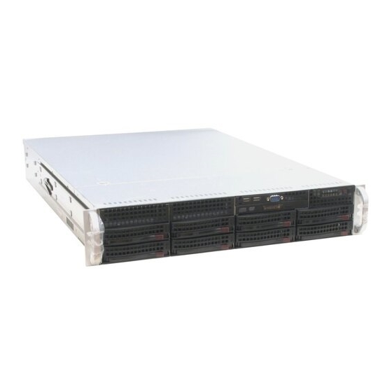
Chapter 1: Introduction Chapter 1 Introduction Overview The SuperServer 6025B-TR+/6025B-8R+ is a high-end server that is comprised of two main subsystems: the SC825TQ-R700LP/SC825S2-R700LP 2U server chassis and the X7DBE+/X7DB8+ dual Intel Xeon processor serverboard. Please refer to our web site for information on operating systems that have been certifi ed for use with the SuperServer 6025B-TR+/6025B-8R+ (www.supermicro.com). -
Page 12: Serverboard Features
UPER ERVER 6025B-TR+/6025B-8R+ User's Manual SATA Accessories (6025B-TR+ only) One (1) SATA backplane (BPN-SAS-825TQ) Six (6) SATA cables (CBL-0061L) Two (2) SATA LED cables (CBL-0157L) Eight (8) SATA hot-swap drive carriers [MCP-220-00001-03(01)]* (The chassis has eight carriers but only six SATA drives are supported.) *The 6025B-TR+/6025B-8R+ is available in silver and black;... - Page 13 Chapter 1: Introduction Serial ATA A SATA controller is integrated into the South Bridge of the 5000P chipset to provide a six-port Serial ATA subsystem, which is RAID 0, 1, 10 and 5 supported. The Serial ATA drives are hot-swappable units. Note: The operating system you use must have RAID support to enable the hot- swap capability and RAID function of the Serial ATA drives.
-
Page 14: Server Chassis Features
UPER ERVER 6025B-TR+/6025B-8R+ User's Manual Server Chassis Features The following is a general outline of the main features of the SC825TQ-R700LP/ SC825S2-R700LP server chassis. System Power The SC825TQ-R700LP/SC825S2-R700LP features a redundant 700W power sup- ply composed of two separate power modules. This power redundancy feature allows you to replace a failed power supply without shutting down the system. - Page 15 Chapter 1: Introduction Cooling System The SC825TQ-R700LP/SC825S2-R700LP chassis has an innovative cooling de- sign that includes three 8-cm hot-plug system cooling fans located in the middle section of the chassis. An air shroud channels the airfl ow from the system fans to effi...
-
Page 16: Contacting Supermicro
UPER ERVER 6025B-TR+/6025B-8R+ User's Manual Contacting Super Micro Headquarters Address: Super Micro Computer, Inc. 980 Rock Ave. San Jose, CA 95131 U.S.A. Tel: +1 (408) 503-8000 Fax: +1 (408) 503-8008 Email: marketing@supermicro.com (General Information) support@supermicro.com (Technical Support) Web Site: www.supermicro.com Europe Address: Super Micro Computer B.V. -
Page 17: Chapter 2: Server Installation
Chapter 2: Server Installation Chapter 2 Server Installation 2-1 Overview This chapter provides a quick setup checklist to get your SuperServer 6025B-TR+/ 6025B-8R+ up and running. Following these steps in the order given should enable you to have the system operational within a minimum amount of time. This quick setup assumes that your system has come to you with the processors and memory preinstalled. -
Page 18: Choosing A Setup Location
UPER ERVER 6025B-TR+/6025B-8R+ User's Manual Choosing a Setup Location - Leave enough clearance in front of the rack to enable you to open the front door completely (~25 inches). - Leave approximately 30 inches of clearance in the back of the rack to allow for suffi... -
Page 19: Rack Mounting Considerations
Chapter 2: Server Installation Rack Mounting Considerations Ambient Operating Temperature If installed in a closed or multi-unit rack assembly, the ambient operating tempera- ture of the rack environment may be greater than the ambient temperature of the room. Therefore, consideration should be given to installing the equipment in an environment compatible with the manufacturer’s maximum rated ambient tempera- ture (Tmra). -
Page 20: Installing The System Into A Rack
UPER ERVER 6025B-TR+/6025B-8R+ User's Manual Installing the System into a Rack This section provides information on installing the SuperServer 6025B-TR+/6025B- 8R+ into a rack unit. If the 6025B-TR+/6025B-8R+ has already been mounted into a rack, you can skip ahead to Sections 2-5 and 2-6. There are a variety of rack units on the market, which may mean the assembly procedure will differ slightly. - Page 21 Chapter 2: Server Installation Figure 2-1. Installing Chassis Rails...
-
Page 22: Installing The Rack Rails
UPER ERVER 6025B-TR+/6025B-8R+ User's Manual Installing the Rack Rails: Determine where you want to place the SuperServer 6025B-TR+/6025B-8R+ in the rack. (See Rack and Server Precautions in Section 2-3.) Position the fi xed rack rail/sliding rail guide assemblies (made up of two inter-locking sections) at the desired location in the rack, keeping the sliding rail guide facing the inside of the rack and the rollers toward the front of the rack. - Page 23 Chapter 2: Server Installation Figure 2-2. Installing the Server into a Rack...
-
Page 24: Checking The Serverboard Setup
UPER ERVER 6025B-TR+/6025B-8R+ User's Manual Checking the Serverboard Setup After you install the 6025B-TR+/6025B-8R+ in the rack, you will need to open the unit to make sure the serverboard is properly installed and all the connections have been made. 1. Accessing the inside of the System (see Figure 2-3) First, grasp the two handles on either side and pull the unit straight out until it locks (you will hear a "click"). - Page 25 Chapter 2: Server Installation Figure 2-3. Accessing the Inside of the System...
-
Page 26: Checking The Drive Bay Setup
UPER ERVER 6025B-TR+/6025B-8R+ User's Manual Checking the Drive Bay Setup Next, you should check to make sure the peripheral drives and the Serial ATA drives have been properly installed and all connections have been made. 1. Accessing the drive bays All drives are accessable from the front of the server. -
Page 27: Chapter 3: System Interface
Chapter 3: System Interface Chapter 3 System Interface Overview There are several LEDs on the control panel as well as others on the Serial ATA drive carriers to keep you constantly informed of the overall status of the system as well as the activity and health of specifi... -
Page 28: Control Panel Leds
SUPERSERVER 6025B-TR+/6025B-8R+ User's Manual Control Panel LEDs The control panel located on the front of the chassis has several LEDs. These LEDs provide you with critical information related to different parts of the system. This section explains what each LED indicates when illuminated and any corrective action you may need to take. -
Page 29: Hdd
Chapter 3: System Interface HDD: Indicates IDE channel activity. On the SuperServer 6025B-TR+/6025B- 8R+, this LED indicates SATA/SCSI and/or DVD-ROM drive activity when fl ash- ing. Power: Indicates power is being supplied to the system's power supply units. This LED should normally be illuminated when the system is operating. Drive Carrier LEDs SATA Drives (6025B-TR+) Green: Each Serial ATA drive carrier has a green LED. - Page 30 SUPERSERVER 6025B-TR+/6025B-8R+ User's Manual Notes...
-
Page 31: Chapter 4: System Safety
Chapter 4: System Safety Chapter 4 System Safety Electrical Safety Precautions Basic electrical safety precautions should be followed to protect yourself from harm and the SuperServer 6025B-TR+/6025B-8R+ from damage: Be aware of the locations of the power on/off switch on the chassis as well as the room's emergency power-off switch, disconnection switch or electrical outlet. -
Page 32: General Safety Precautions
UPER ERVER 6025B-TR+/6025B-8R+ User's Manual The power supply power cord must include a grounding plug and must be plugged into grounded electrical outlets. Serverboard Battery: CAUTION - There is a danger of explosion if the onboard battery is installed upside down, which will reverse its polarities (see Figure 4-1). -
Page 33: Esd Precautions
Chapter 4: System Safety or be pulled into a cooling fan. Remove any jewelry or metal objects from your body, which are excellent metal conductors that can create short circuits and harm you if they come into contact with printed circuit boards or areas where power is present. After accessing the inside of the system, close the system back up and secure it to the rack unit with the retention screws after ensuring that all connections have been made. -
Page 34: Operating Precautions
UPER ERVER 6025B-TR+/6025B-8R+ User's Manual For grounding purposes, make sure your computer chassis provides excellent conductivity between the power supply, the case, the mounting fasteners and the serverboard. Operating Precautions Care must be taken to assure that the chassis cover is in place when the 6025B-TR+/6025B-8R+ is operating to assure proper cooling. -
Page 35: Chapter 5: Advanced Serverboard Setup
Chapter 5: Advanced Serverboard Setup Chapter 5 Advanced Serverboard Setup This chapter covers the steps required to install processors and heatsinks to the X7DBE+/X7DB8+ serverboard, connect the data and power cables and install add- on cards. All serverboard jumpers and connections are described and a layout and quick reference chart are included in this chapter. -
Page 36: Processor And Heatsink Installation
UPERSERVER 6025B-TR+/6025B-8R+ User’s Manual Processor and Heatsink Installation When handling the processor, avoid placing direct pressure on the label area of the fan. Also, do not place the serverboard on a conductive surface, which can damage the BIOS battery and prevent the system from booting up. - Page 37 Chapter 5: Advanced Serverboard Setup 3. Use your thumb and your index fi nger to hold the CPU at opposite sides. 4. Align pin1 of the CPU (the cor- ner marked with a triangle) with the notched corner of the CPU socket. 5.
- Page 38 UPERSERVER 6025B-TR+/6025B-8R+ User’s Manual Installing the Heatsink CEK Passive Heatsink 1. Do not apply any thermal grease to the heatsink or the CPU die; the required amount has already been applied. 2. Place the heatsink on top of the CPU so that the four mounting holes are aligned with those on the (preinstalled) Screw#1...
-
Page 39: Connecting Cables
Chapter 5: Advanced Serverboard Setup Connecting Cables Now that the processors are installed, the next step is to connect the cables to the serverboard. These include the data (ribbon) cables for the peripherals and control panel and the power cables. Connecting Data Cables The ribbon cables used to transfer data from the peripheral devices have been carefully routed in preconfi... -
Page 40: Connecting The Control Panel
UPERSERVER 6025B-TR+/6025B-8R+ User’s Manual Connecting the Control Panel JF1 contains header pins for various front control panel connectors. See Figure 5-3 for the pin locations of the various front control panel buttons and LED indi- cators. Please note that even and odd numbered pins are on opposite sides of each header. -
Page 41: I/O Ports
Chapter 5: Advanced Serverboard Setup I/O Ports The I/O ports are color coded in conformance with the PC 99 specifi cation. See Figure 5-4 below for the colors and locations of the various I/O ports. Figure 5-4. Rear Panel I/O Ports Installing Memory Note: Check the Supermicro web site for recommended memory modules. - Page 42 UPERSERVER 6025B-TR+/6025B-8R+ User’s Manual Memory Support The X7DBE+/X7DB8+ supports up to 64 GB of FBD (Fully Buffered DIMM) ECC DDR2-667/533. Populating with pairs of memory modules that are of the same size and same type will result in interleaved memory. Note: Due to OS limitations, some operating systems may not show more than 4 GB of memory.
-
Page 43: Adding Pci Cards
Chapter 5: Advanced Serverboard Setup Adding PCI Cards 1. PCI slots The X7DBE+/X7DB8+ has six PCI expansion slots, which includes two x8 PCI- Express slots, one x4 PCI-Express slot, two 64-bit 133 MHz PCI-X slots and one 64-bit 100 MHz PCI-X slot. On the X7DB8+, the 100 MHz PCI-X slot supports Zero Channel RAID (ZCR). -
Page 44: Serverboard Details
UPERSERVER 6025B-TR+/6025B-8R+ User’s Manual Serverboard Details Figure 5-6. SUPER X7DB8+ Layout* (not drawn to scale) JPW1 JPW2 JPW3 DIMM 4D FAN7/ FAN5 DIMM 4C CPU FAN1 FAN6 DIMM 4B DIMM 4A SMBUS_PS Speaker DIMM 3D Mouse FAN1 DIMM 3C USB0/1 DIMM 3B DIMM 3A COM1... -
Page 45: X7Db8+X7Dbe+ Quick Reference
Chapter 5: Advanced Serverboard Setup X7DB8+X7DBE+ Quick Reference Jumper Description Default Setting J27/J28 SMBUS to PCI Enable/Disable Closed (Enabled) 3rd Power Fail Detect Open (Disabled) Alarm Reset Open (Disabled) JBT1 CMOS Clear (See Section 5-9) JCF1 Compact Flash Master/Slave Select Closed (Master) JPA1* SCSI Controller Enable/Disable... -
Page 46: Connector Defi Nitions
UPERSERVER 6025B-TR+/6025B-8R+ User’s Manual Connector Defi nitions ATX Power 24-pin Connector Pin Defi nitions (JPW1) Pin# Defi nition Pin # Defi nition ATX Power Connector +3.3V +3.3V The power supply connector meets -12V +3.3V the SSI (Superset ATX) 24-pin specifi - cation. -
Page 47: Hdd Led
Chapter 5: Advanced Serverboard Setup HDD LED HDD LED Pin Defi nitions (JF1) The HDD (IDE Hard Disk Drive) LED Pin# Defi nition connection is located on pins 13 and 14 of JF1. Attach the IDE hard drive HD Active LED cable to display disk activity. -
Page 48: Reset Button
UPERSERVER 6025B-TR+/6025B-8R+ User’s Manual Reset Button Reset Button Pin Defi nitions (JF1) The Reset Button connection is lo- Pin# Defi nition cated on pins 3 and 4 of JF1. Attach Reset it to the hardware reset switch on the Ground computer case. -
Page 49: Serial Ports
Chapter 5: Advanced Serverboard Setup Serial Ports Serial Port Pin Defi nitions (COM1/COM2) The COM1 serial port is located beside Pin # Defi nition Pin # Defi nition the mouse port. COM2 is a header on the serverboard (see serverboard layout for location). -
Page 50: Extra Universal Serial Bus Headers
UPERSERVER 6025B-TR+/6025B-8R+ User’s Manual Extra Universal Serial Bus Front Panel Universal Serial Bus Pin Defi nitions (JUSB2/3) Headers USB2 USB3 Pin # Defi nition Pin # Defi nition Three additional USB headers are located near the WOL header on the serverboard. -
Page 51: Wake-On-Lan
Chapter 5: Advanced Serverboard Setup Wake-On-LAN Wake-On-LAN Pin Defi nitions (WOL) Pin# Defi nition The Wake-On-LAN header is desig- +5V Standby nated WOL. See the table on the right for pin defi nitions. You must enable Ground the LAN Wake-Up setting in BIOS to Wake-up use this feature. -
Page 52: Sgpio
UPERSERVER 6025B-TR+/6025B-8R+ User’s Manual SGPIO The two headers labeled SGPIO1 and SGPIO2 are for SGPIO (Serial General Purpose Input/Output). SGPIO provides a bus between the SATA controller and the SATA drive backplane to provide SATA enclosure management functions. Connect the appropriate cables from the backplane to the SGPIO1 and SGPIO2 headers to utilize SATA management functions on your system. -
Page 53: Jlan Enable/Disable
Chapter 5: Advanced Serverboard Setup JLAN Enable/Disable JLAN Enable/Disable Jumper Settings (JPL1/JPL2) Change the setting of jumper JPL1 Jumper Setting Defi nition and JPL2 to enable or disable the on- Pins 1-2 Enabled board LAN ports JLAN1 and JLAN2, Pins 2-3 Disabled respectively. -
Page 54: Alarm Reset
UPERSERVER 6025B-TR+/6025B-8R+ User’s Manual Alarm Reset (JAR) The system will notify you in the event Alarm Reset of a power supply failure. This feature Jumper Settings (JAR) assumes that Supermicro redundant Pin# Defi nition power supply units are installed in the chassis. -
Page 55: Compact Flash Master/Slave Select
Chapter 5: Advanced Serverboard Setup Compact Flash Master/Slave Select Compact Flash Card Master/ Slave Select (JCF1) A Compact Flash Master (Primary)/Slave Jumper Defi nition (Secondary) Select jumper is located at Open Slave (Secondary) JCF1. Close this jumper to enable the Closed Master (Primary) use of a compact fl... -
Page 56: 5-10 Onboard Indicators
UPERSERVER 6025B-TR+/6025B-8R+ User’s Manual 5-10 Onboard Indicators JLAN Left LED (Connection Speed Indicator) JLAN1/JLAN2 LEDs LED Color Defi nition 10 MHz Each Ethernet port has two LEDs. Green 100 MHz The yellow (right) LED indicates activ- Amber 1 GHz ity while the left LED may be green, amber or off to indicate the speed of the connection. -
Page 57: 5-11 Parallel Port, Floppy And Hard Drive Connections
Chapter 5: Advanced Serverboard Setup 5-11 Parallel Port, Floppy and Hard Drive Connections Note the following when connecting the fl oppy and hard disk drive cables: • The fl oppy disk drive cable has seven twisted wires. • A red mark on a wire typically designates the location of pin 1. •... -
Page 58: Floppy Connector
UPERSERVER 6025B-TR+/6025B-8R+ User’s Manual Floppy Connector The fl oppy connector is located near the IDE connectors. See the table below for pin defi nitions. Floppy Drive Connector Pin Defi nitions (Floppy) Pin# Defi nition Pin # Defi nition Ground FDHDIN Ground Reserved FDEDIN... -
Page 59: Ide Connectors
Chapter 5: Advanced Serverboard Setup IDE Connectors There are two IDE connectors: IDE#1 (blue) and IDE#2 (white). IDE#1 is designated as the primary IDE drive. IDE#2 is designated as the secondary IDE drive and is reserved for Compact Flash card use only. See the table below for pin defi... -
Page 60: Ultra320 Scsi Connectors
UPERSERVER 6025B-TR+/6025B-8R+ User’s Manual Ultra320 SCSI Connectors (6025B-8R+ only) There are two SCSI connectors on the serverboard. SCSI Channel A is Ultra320 SCSI Drive Connector located at JA1 and SCSI Channel B Pin Defi nitions (JA1/JA2) is located at JA2. Refer to the table Pin# Defi... -
Page 61: Chapter 6: Advanced Chassis Setup
Chapter 6: Advanced Chassis Setup Chapter 6 Advanced Chassis Setup This chapter covers the steps required to install components and perform mainte- nance on the SC825TQ-R700LP/SC825S2-R700LP chassis. For component instal- lation, follow the steps in the order given to eliminate the most common problems encountered. -
Page 62: Control Panel
UPER ERVER 6025B-TR+/6025B-8R+ User's Manual Figure 6-1. Front and Rear Chassis Views 3.5" Drive Bays (2) Slim DVD-ROM Drive USB Ports (2), COM Port Control Panel Hard Drives (8) Floppy Drive (optional) System Reset Main Power Keyboard/Mouse Ports Parallel Port 7 Low-Profi... -
Page 63: System Fans
Chapter 6: Advanced Chassis Setup System Fans Three 8-cm hot-swap fans provide the cooling for the SuperServer 6025B-TR+/ 6025B-8R+. It is very important that the chassis top cover is properly installed and making a good seal in order for the cooling air to circulate properly through the chassis and cool the components. -
Page 64: Drive Bay Installation
UPER ERVER 6025B-TR+/6025B-8R+ User's Manual Figure 6-2. Removing System Cooling Fans Drive Bay Installation/Removal Accessing the Drive Bays SATA/SCSI Drives: You do not need to access the inside of the chassis or remove power to replace or swap SATA/SCSI drives. Proceed to the next step for instruc- tions. -
Page 65: Sata/Scsi Drive Installation
Chapter 6: Advanced Chassis Setup SATA/SCSI Drive Installation 1. Mounting a SATA/SCSI drive in a drive carrier The SATA/SCSI drives are mounted in drive carriers to simplify their installation and removal from the chassis. These carriers also help promote proper airfl ow for the drives. - Page 66 UPER ERVER 6025B-TR+/6025B-8R+ User's Manual 2. Installing/removing hot-swap SATA/SCSI drives The SATA/SCSI drive carriers are all easily accessible at the front of the chassis. These hard drives are hot-pluggable, meaning they can be removed and installed without powering down the system. To remove a carrier, push the release button located beside the drive LEDs.
-
Page 67: Dvd-Rom And Floppy Drive Installation
Chapter 6: Advanced Chassis Setup Hard Drive Backplane The SATA/SCSI drives plug into a backplane that provides power, drive ID and bus termination. A RAID controller can be used with the backplane to provide data security. The operating system you use must have RAID support to enable the hot- swap capability of the Serial ATA drives. -
Page 68: Power Supply
UPER ERVER 6025B-TR+/6025B-8R+ User's Manual Power Supply The SuperServer 6025B-TR+/6025B-8R+ has a 700 watt redundant power supply consisting of two power modules. Each power supply module has an auto-switching capability, which enables it to automatically sense and operate at a 100V - 240V input voltage. -
Page 69: Chapter 7: Bios
Chapter 7: BIOS Chapter 7 BIOS Introduction This chapter describes the Phoenix BIOS™ Setup utility for the X7DBE+/X8DB8+. The Phoenix ROM BIOS is stored in a fl ash chip and can be easily upgraded using a fl oppy disk-based program. Note: Due to periodic changes to the BIOS, some settings may have been added or deleted and might not yet be recorded in this manual. -
Page 70: Running Setup
UPERSERVER 6025B-TR+/6025B-8R+ User’s Manual Running Setup Default settings are in bold text unless otherwise noted. The BIOS setup options described in this section are selected by choosing the ap- propriate text from the main BIOS Setup screen. All displayed text is described in this section, although the screen display is often all you need to understand how to set the options (see next page). -
Page 71: Main Setup Features
Chapter 7: BIOS Main BIOS Setup Menu Main Setup Features System Time To set the system date and time, key in the correct information in the appropriate fi elds. Then press the <Enter> key to save the data. System Date Using the arrow keys, highlight the month, day and year fi... - Page 72 UPERSERVER 6025B-TR+/6025B-8R+ User’s Manual IDE Channel 0 Master/Slave, SATA Port0, SATA Port1, SATA Port2 and SATA Port3 These settings allow the user to set the parameters of IDE Channel 0 Master/ Slave, IDE Channel 1 Master/Slave, IDE Channel 2 Master, IDE Channel 3 Master slots.
- Page 73 Chapter 7: BIOS CHS Format The following items will be displayed by the BIOS: Type: This item displays the type of CPU. Cylinders: This item indicates the status of cylinders. Headers: This item indicates the number of headers. Sectors: This item displays the number of sectors. Maximum Capacity: This item displays the maximum storage capacity of the system.
- Page 74 UPERSERVER 6025B-TR+/6025B-8R+ User’s Manual Parallel ATA This setting allows the user to enable or disable the function of Parallel ATA. The options are Disabled, Channel 0, Channel 1, and Both. Serial ATA This setting allows the user to enable or disable the function of Serial ATA. The options are Disabled and Enabled.
-
Page 75: Advanced Setup
Chapter 7: BIOS System Memory This display informs you how much system memory is recognized as being present in the system. Extended Memory This display informs you how much extended memory is recognized as being present in the system. Advanced Setup Choose Advanced from the Phoenix BIOS Setup Utility main menu with the arrow keys. - Page 76 UPERSERVER 6025B-TR+/6025B-8R+ User’s Manual Boot Features Access the submenu to make changes to the following settings. Quick Boot Mode If enabled, this feature will speed up the POST (Power On Self Test) routine by skipping certain tests after the computer is turned on. The settings are Enabled and Disabled.
- Page 77 Chapter 7: BIOS Memory Cache Cache System BIOS Area This setting allows you to designate a reserve area in the system memory to be used as a System BIOS buffer to allow the BIOS write (cache) its data into this reserved memory area.
- Page 78 UPERSERVER 6025B-TR+/6025B-8R+ User’s Manual Select "Uncached" to disable this function. Select "Write Through" to allow data to be cached into the buffer and written into the system memory at the same time. Select "Write Protect" to prevent data from being written into the base memory area of Block 0-512K.
- Page 79 Chapter 7: BIOS Slot#1 PCI 100 MHz ZCR, Slot#2 PCI-X 133MHz, Slot#3 PCI-X 133MHz, Slot#4 PCI-Exp x8, Slot#5 PCI-Exp x8, and Slot#6 PCI-Exp Access the submenu for each of the settings above to make changes to the following: Option ROM Scan When enabled, this setting will initialize the device expansion ROM.
- Page 80 UPERSERVER 6025B-TR+/6025B-8R+ User’s Manual Memory Branch Mode This option allows the BIOS to enumerate Host Mode for Device 16, Function 1, Reg. 40h bit 16 and Reg. 58h [14]. The options are Interleave, Sequential, Mirroring, and Single Channel 0. Branch 0 Rank Sparing Select enable to enable the sparing feature for Branch 0 Rank.
- Page 81 Chapter 7: BIOS Advanced Processor Options Access the submenu to make changes to the following settings. CPU Speed This is a display that indicates the speed of the installed processor. Hyper-threading (Available when supported by the CPU.) Set to Enabled to use the Hyper-Threading Technology, which will result in increased CPU performance.
- Page 82 UPERSERVER 6025B-TR+/6025B-8R+ User’s Manual Set Maximum Extended CPUID=3 Select Enabled to set the Maximum Extended CPUID value to 3. The options are Enabled and Disabled. Intel <R> Virtualization Technology Select Enabled to use the feature of Virtualization Technology. The options are Enabled and Disabled.
- Page 83 Chapter 7: BIOS Parallel Port This setting allows you to assign control of the parallel port. The options are Enabled (user defi ned), Disabled and Auto (BIOS-or OS- controlled). Base I/O Address Select the base I/O address for the parallel port. The options are 378, 278 and 3BC.
- Page 84 UPERSERVER 6025B-TR+/6025B-8R+ User’s Manual DMI Event Logging Access the submenu to make changes to the following settings. Event Log Validity This is a display to inform you of the event log validity. It is not a setting. Event Log Capacity This is a display to inform you of the event log capacity.
- Page 85 Chapter 7: BIOS Console Redirection Access the submenu to make changes to the following settings. COM Port Address This item allows you to specify to redirect the console to Onboard COM A or Onboard COM B. This setting can also be Disabled. BAUD Rate This item allows you to select the BAUD rate for console redirection.
- Page 86 UPERSERVER 6025B-TR+/6025B-8R+ User’s Manual Hardware Monitor Logic CPU Temperature Threshold This option allows the user to set a CPU temperature threshold that will activate the alarm system when the CPU temperature reaches this pre-set temperature threshold. The options are 70 C, 75 C, 80 C and 85...
-
Page 87: Security
Chapter 7: BIOS Security Choose Security from the Phoenix BIOS Setup Utility main menu with the arrow keys. You should see the following display. Security setting options are displayed by highlighting the setting using the arrow keys and pressing <Enter>. All Security BIOS settings are described in this section. -
Page 88: Boot
UPERSERVER 6025B-TR+/6025B-8R+ User’s Manual Set User Password When the item "Set User Password" is highlighted, hit the <Enter> key. When prompted, type the user's password in the dialogue box to set or to change the user's password, which allows access to the system at boot-up. Password on Boot This setting allows you to require a password to be entered when the system boots up. -
Page 89: Exit
Chapter 7: BIOS Boot Priority Order/Excluded from Boot Order. Use the Up and Down Arrow Keys to select a device. Use a <+> key or a <-> key to move the device up or down. Use the <f> key or the <r> key to specify the devices. You can also use the keys indicated above to specify the priority of boot order of a device or to move items from the category of "Excluded from Boot Order"... - Page 90 UPERSERVER 6025B-TR+/6025B-8R+ User’s Manual Exit Saving Changes Highlight this item and hit <Enter> to save any changes you made and to exit the BIOS Setup utility. Exit Discarding Changes Highlight this item and hit <Enter> to exit the BIOS Setup utility without saving any changes you may have made.
-
Page 91: Appendix A: Bios Post Messages
Appendix A: BIOS POST Messages Appendix A BIOS POST Messages During the Power-On Self-Test (POST), the BIOS will check for problems. If a prob- lem is found, the BIOS will activate an alarm or display a message. The following is a list of such BIOS messages. - Page 92 UPERSERVER 6025B-TR+/6025B-8R+ User’s Manual System CMOS checksum bad - Default confi guration used System CMOS has been corrupted or modifi ed incorrectly, perhaps by an application program that changes data stored in CMOS. The BIOS installed Default Setup Values. If you do not want these values, enter Setup and enter your own values. If the error persists, check the system battery or contact your dealer.
- Page 93 Appendix A: BIOS POST Messages System cache error - Cache disabled RAM cache failed and BIOS disabled the cache. On older boards, check the cache jumpers. You may have to replace the cache. See your dealer. A disabled cache slows system performance considerably.
- Page 94 UPERSERVER 6025B-TR+/6025B-8R+ User’s Manual Fixed Disk n Fixed disk n (0-3) identifi ed. Invalid System Confi guration Data Problem with NVRAM (CMOS) data. I/O device IRQ confl ict I/O device IRQ confl ict error. PS/2 Mouse Boot Summary Screen: PS/2 Mouse installed. nnnn kB Extended RAM Passed Where nnnn is the amount of RAM in kilobytes successfully tested.
- Page 95 Appendix A: BIOS POST Messages Parity Check 2 nnnn Parity error found in the I/O bus. BIOS attempts to locate the address and display it on the screen. If it cannot locate the address, it displays ????. Press <F1> to resume, <F2> to Setup, <F3> for previous Displayed after any recoverable error message.
- Page 96 UPERSERVER 6025B-TR+/6025B-8R+ User’s Manual Notes...
-
Page 97: Appendix B: Bios Post Codes
Appendix B: BIOS POST Codes Appendix B BIOS POST Codes This section lists the POST (Power On Self Test) codes for the PhoenixBIOS. POST codes are divided into two categories: recoverable and terminal. Recoverable POST Errors When a recoverable type of error occurs during POST, the BIOS will display an POST code that describes the problem. - Page 98 UPERSERVER 6025B-TR+/6025B-8R+ User’s Manual POST Code Description 1-2-2-3 BIOS ROM checksum Initialize cache before memory Auto size 8254 timer initialization 8237 DMA controller initialization Reset Programmable Interrupt Controller 1-3-1-1 Test DRAM refresh 1-3-1-3 Test 8742 Keyboard Controller Set ES segment register to 4 GB Auto size DRAM Initialize POST Memory Manager Clear 512 kB base RAM...
- Page 99 Appendix B: BIOS POST Codes POST Code Description Disable CPU cache Test RAM between 512 and 640 kB Test extended memory Test extended memory address lines Jump to UserPatch1 Confi gure advanced cache registers Initialize Multi Processor APIC Enable external and CPU caches Setup System Management Mode (SMM) area Display external L2 cache size Load custom defaults (optional)
- Page 100 UPERSERVER 6025B-TR+/6025B-8R+ User’s Manual POST Code Description Check for SMART Drive (optional) Shadow option ROMs Set up Power Management Initialize security engine (optional) Enable hardware interrupts Determine number of ATA and SCSI drives Set time of day Check key lock Initialize typematic rate Erase F2 prompt Scan for F2 key stroke...
- Page 101 Appendix B: BIOS POST Codes POST Code Description Re-map I/O and memory for PCMCIA Initialize digitizer and display message Unknown interrupt The following are for boot block in Flash ROM POST Code Description Initialize the chipset Initialize the bridge Initialize the CPU Initialize system timer Initialize system I/O Check force recovery boot...
- Page 102 UPERSERVER 6025B-TR+/6025B-8R+ User’s Manual Notes...
-
Page 103: Appendix C: Software Installation
Appendix C: Software Installation Appendix C Software Installation After all the hardware has been installed, you must fi rst confi gure Intel's ESB2 SATA RAID* before you install the Windows Operating System and other software drivers. Important Notes: If you do not wish to confi gure onboard SATA RAID functions, please go directly to Section C-3. - Page 104 UPERSERVER 6025B-TR+/6025B-8R+ User’s Manual RAID Confi gurations The following types of RAID confi gurations are supported: RAID 0 (Data Striping): this writes data in parallel, interleaved ("striped") sections of two hard drives. Data transfer rate is doubled over using a single disk. RAID1 (Data Mirroring): an identical data image from one drive is copied to another drive.
- Page 105 Appendix C: Software Installation Using the Intel ESB2 SATA RAID Utility Program 1. Creating, Deleting and Resetting RAID Volumes a. After the system exits from the BIOS Setup Utility, it will automatically reboot. The following screen appears after the Power-On Self Test. b.
- Page 106 UPERSERVER 6025B-TR+/6025B-8R+ User’s Manual Creating a RAID 0 Volume a. Select "Create RAID Volume" from the main menu and press the <Enter> key. The following screen will appear: b. Specify a name for the RAID 0 set and press the <Tab> key or the <Enter> key to go to the next fi...
- Page 107 Appendix C: Software Installation Creating a RAID 1 Volume a. Select "Create RAID Volume" from the main menu and press the <Enter> key. The following screen will appear: b. Specify a name for the RAID 1 set and press the <Tab> key or the <Enter> key to go to the next fi...
- Page 108 UPERSERVER 6025B-TR+/6025B-8R+ User’s Manual Creating a RAID 10 (RAID 1+ RAID 0) a. Select "Create RAID Volume" from the main menu and press the <Enter> key. The following screen will appear: b. Specify a name for the RAID 10 set and press <Enter>. c.
- Page 109 Appendix C: Software Installation Creating a RAID 5 Set (Parity) a. Select "Create RAID Volume" from the main menu and press the <Enter> key. The following screen will appear: b. Specify a name for the RAID 5 set and press <Enter>. c.
- Page 110 UPERSERVER 6025B-TR+/6025B-8R+ User’s Manual Deleting a RAID Volume Warning! Be sure to back up your data before deleting a RAID set. You will lose all data on the disk drives when deleting a RAID set. a. From the main menu, select item2-Delete RAID Volume, and press <Enter>. b.
- Page 111 Appendix C: Software Installation Resetting to Non-RAID and Resetting a RAID HDD Warning! Use cautious when resetting a RAID volume HDD to non- RAID or resetting a RAID HDD. Resetting a RAID volume HDD or resetting a RAID HDD will reformat the HDD and delete the internal RAID structure on the drive.
- Page 112 UPERSERVER 6025B-TR+/6025B-8R+ User’s Manual C-2 Installing Windows XP/2000/2003 for RAID Systems New Operating System-Windows XP/2000/2003 Installation a. Insert the Microsoft Windows XP/2000/2003 Setup CD in the CD drive and the system will start booting up from CD. b. Press the <F6> key when the message "Press F6 if you need to install a third party SCSI or RAID driver"...
-
Page 113: Software Programs
Appendix C: Software Installation C-3 Installing the Operating System and other Software Programs After all the hardware has been installed, you must fi rst install the operating system, and then, other software drivers. The necessary drivers are all included on the Supermicro CDs that came packaged with your motherboard. - Page 114 Supero Doctor III displays crucial system information such as CPU temperature, system voltages and fan status. See the Figure below for a display of the Supero Doctor III interface. Note: The default User Name and Password for SuperDoctor III is ADMIN / AD- MIN.
- Page 115 Appendix C: Software Installation Figure C-3. Supero Doctor III Display: Remote Control Note: SD III Software Revision 1.0 can be downloaded from our Web Site at: ftp:// ftp.supermicro.com/utility/Supero_Doctor_III/. You can also download SDIII User's Guide at: http://www.supermicro.com/PRODUCT/Manuals/SDIII/UserGuide.pdf. For Linux, we will still recommend Supero Doctor II.
- Page 116 UPERSERVER 6025B-TR+/6025B-8R+ User’s Manual Notes C-14...
-
Page 117: Appendix D: System Specifi Cations
Appendix D: System Specifi cations Appendix D System Specifi cations Processors Single or dual Intel® Xeon™ LGA 771 type processors at a front side (system) bus speed of 1333 MHz. Note: Please refer to our web site for a complete listing of supported processors. Chipset Intel 5000P/ESB2 chipset BIOS... - Page 118 UPER ERVER 6025B-TR+/6025B-8R+ User's Manual Serverboard 6025B-TR+: X7DBE+ (Extended ATX form factor) 6025B-8R+: X7DB8+ (Extended ATX form factor) Dimensions: 13.5 x 13.05 in (343 x 332 mm) Chassis 6025B-TR+: SC825TQ-R700LP, 2U rackmount 6025B-8R+: SC825S2-R700LP, 2U rackmount Dimensions (both): (WxHxD) 16.8 x 3.5 x 25.5 in. (427 x 89 x 648 mm) Weight Gross (Bare Bone): 57 lbs.
- Page 119 Appendix D: System Specifi cations Regulatory Compliance Electromagnetic Emissions: FCC Class A, EN 55022 Class A, EN 61000-3-2/-3-3, CISPR 22 Class A Electromagnetic Immunity: EN 55024/CISPR 24, (EN 61000-4-2, EN 61000-4-3, EN 61000-4-4, EN 61000-4-5, EN 61000-4-6, EN 61000-4-8, EN 61000-4-11) Safety: EN 60950/IEC 60950-Compliant, UL Listed (USA), CUL Listed (Canada), TUV Certifi...
- Page 120 UPER ERVER 6025B-TR+/6025B-8R+ User's Manual Notes...
Need help?
Do you have a question about the SUPERSERVER 6025B-TR+ and is the answer not in the manual?
Questions and answers