
Related Manuals for Supero SUPERO SUPERSERVER 6026TT-BTF


Summary of Contents for Supero SUPERO SUPERSERVER 6026TT-BTF
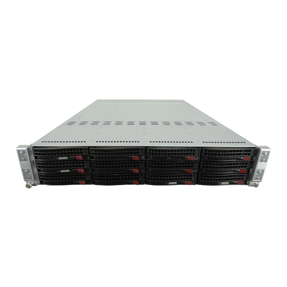
- Page 1 ® UPER 6026TT-BT(R)F UPER ERVER 6026TT-BIBX(R)F UPER ERVER 6026TT-BIBQ(R)F UPER ERVER USER’S MANUAL Revision 1.0a...
- Page 2 Please Note: For the most up-to-date version of this manual, please see our web site at www.supermicro.com. Super Micro Computer, Inc. ("Supermicro") reserves the right to make changes to the product described in this manual at any time and without notice. This product, including software, if any, and documentation may not, in whole or in part, be copied, photocopied, reproduced, translated or reduced to any medium or machine without prior written consent.
-
Page 3: About This Manual
Preface Preface About This Manual This manual is written for professional system integrators and PC technicians. It provides information for the installation and use of the SuperServer 6026TT-BT(R) F/BIBX(R)F/BIBQ(R)F. Installation and maintenance should be performed by expe- rienced technicians only. The SuperServer SuperServer 6026TT-BT(R)F/BIBX(R)F/BIBQ(R)F is a 2U Twin (four serverboards/nodes in a 2U chassis) rackmount server based on the SC827B- (R)1400B server chassis and four Super X8DTT-F/X8DTT-IBXF/X8DTT-IBQF... - Page 4 UPER ERVER 6026TT-BT(R)F/BIBX(R)F/BIBQ(R)F User's Manual Chapter 4: System Safety You should thoroughly familiarize yourself with this chapter for a general overview of safety precautions that should be followed when installing and servicing the SuperServer 6026TT-BT(R)F/BIBX(R)F/BIBQ(R)F. Chapter 5: Advanced Serverboard Setup Chapter 5 provides detailed information on the X8DTT-F/X8DTT-IBXF/X8DTT-IBQF serverboard, including the locations and functions of connectors, headers and jump- ers.
- Page 5 Preface Notes...
-
Page 6: Table Of Contents
2U Twin : System Notes ................. 1-6 Nodes ......................1-6 System Power ....................1-6 SATA Backplane/Drives ................... 1-6 Contacting Supermicro ..................1-7 Chapter 2 Server Installation Overview ......................2-1 Unpacking the System ..................2-1 Preparing for Setup ..................2-1 Choosing a Setup Location ................2-2 Rack Precautions .................... - Page 7 Table of Contents Removing the Protective Film ................. 2-4 Rack Mounting Instructions ................2-5 Separating the Sections of the Rack Rails ............. 2-5 Installing the Inner Rail Extensions ..............2-6 Outer Rack Rails ..................... 2-7 Checking the Serverboard Setup ..............2-9 Preparing to Power On .................
- Page 8 UPER ERVER 6026TT-BT(R)F/BIBX(R)F/BIBQ(R)F User's Manual 5-11 Confi guring Supero Doctor III ............... 5-20 Chapter 6 Advanced Chassis Setup Static-Sensitive Devices .................. 6-1 Precautions ..................... 6-1 Unpacking ....................... 6-1 Control Panel ....................6-2 System Fans ....................6-2 Fan Confi guration .................... 6-3 System Fan Failure ..................
-
Page 9: Chapter 1 Introduction
SC827B-(R)1400B 2U chassis and four X8DTT-F/X8DTT-IBXF/ X8DTT-IBQF serverboards. Please refer to our web site for information on operating systems that have been certifi ed for use with the 6026TT (www.supermicro.com). In addition to the serverboard and chassis, various hardware components may have been included with the system, as listed below. -
Page 10: Serverboard Features
Processors Each X8DTT-F/X8DTT-IBXF/X8DTT-IBQF supports two Intel® 5500 Series proces- sors in LGA1366 sockets. Please refer to our web site for a complete listing of supported processors (www.supermicro.com). Memory Each X8DTT-F/X8DTT-IBXF/X8DTT-IBQF has twelve 240-pin DIMM sockets that can support up to 96 GB of registered ECC DDR3-1333/1066/800 SDRAM (384 GB for the system). -
Page 11: Onboard Controllers/Ports
Chapter 1: Introduction Onboard Controllers/Ports Onboard I/O backpanel ports on each serverboard include one COM port, a VGA port, two USB ports, a dedicated IPMI LAN port and two Gigabit LAN (NIC) ports. An Infi niBand port is also included on the X8DTT-IBXF/X8DTT-IBQF serverboards (the 6026TT-BIBX(R)F and 6026TT-BIBQ(R)F only). - Page 12 UPER ERVER 6026TT-BT(R)F/BIBX(R)F/BIBQ(R)F User's Manual CPU#1 CPU#2 Port1 Port0 Ports 2,1 Kawela MT25408 QSFP Ports Connect-X IB PCI-E Gen2/DDR or QDR Intel Ports RJ45 RJ45 5520 Ports PCI-E x16 7,8,9,10 SST25 VF016 CLINK CLINK ICH10R PE 4-1 SATA SATA #1 SATA #2 SATA #3 SATA #4...
-
Page 13: Server Chassis Features
Chapter 1: Introduction Server Chassis Features The following is a general outline of the main features of the SC827B-(R)1400B 2U chassis. Details on the chassis can be found in Chapter 6. System Power When confi gured as a SuperServer 6026TT-BT(R)F/BIBX(R)F/BIBQ(R)F, the SC827B-(R)1400B includes a single 1400W power supply, which provides power to all four serverboards (nodes). -
Page 14: Twin 2 : System Notes
UPER ERVER 6026TT-BT(R)F/BIBX(R)F/BIBQ(R)F User's Manual 2U Twin : System Notes As a 2U Twin confi guration, the 6026TT-BT(R)F/BIBX(R)F/BIBQ(R)F is a unique server system. With four system boards incorporated into a single chassis acting as four separate nodes, there are several points you should keep in mind. Nodes Each of the four serverboards act as a separate node in the system. -
Page 15: Contacting Supermicro
Super Micro Computer, Inc. 980 Rock Ave. San Jose, CA 95131 U.S.A. Tel: +1 (408) 503-8000 Fax: +1 (408) 503-8008 Email: marketing@supermicro.com (General Information) support@supermicro.com (Technical Support) Web Site: www.supermicro.com Europe Address: Super Micro Computer B.V. Het Sterrenbeeld 28, 5215 ML... - Page 16 UPER ERVER 6026TT-BT(R)F/BIBX(R)F/BIBQ(R)F User's Manual Notes...
-
Page 17: Chapter 2 Server Installation
Chapter 2: Server Installation Chapter 2 Server Installation Overview This chapter provides a quick setup checklist to get the 6026TT-BT(R)F/BIBX(R)F/ BIBQ(R)F up and running. Following these steps in the order given should enable you to have the system operational within a minimum amount of time. This quick setup assumes that your system has come to you with the processors and memory preinstalled. -
Page 18: Choosing A Setup Location
UPER ERVER 6026TT-BT(R)F/BIBX(R)F/BIBQ(R)F User's Manual Choosing a Setup Location • Leave enough clearance in front of the rack to enable you to open the front door completely (~25 inches). • Leave approximately 30 inches of clearance in the back of the rack to allow for suffi... -
Page 19: Rack Mounting Considerations
Chapter 2: Server Installation • Allow the hot plug SATA drives and power supply modules to cool before touch- ing them. • Always keep the rack's front door and all panels and components on the servers closed when not servicing to maintain proper cooling. •... -
Page 20: Removing The Protective Film
UPER ERVER 6026TT-BT(R)F/BIBX(R)F/BIBQ(R)F User's Manual Removing the Protective Film Before operating the SC827 chassis for the fi rst time, it is important to remove the protective fi lm covering the top of the chassis, in order to allow for proper ventila- tion and cooling. -
Page 21: Rack Mounting Instructions
Chapter 2: Server Installation Rack Mounting Instructions This section provides information on installing the SC827 chassis into a rack unit with the quick-release rails provided. There are a variety of rack units on the market, which may mean the assembly procedure will differ slightly. You should also refer to the installation instructions that came with the rack unit you are using. -
Page 22: Installing The Inner Rail Extensions
UPER ERVER 6026TT-BT(R)F/BIBX(R)F/BIBQ(R)F User's Manual Installing the Inner Rail Extensions The SC827 chassis includes a set of inner rails in two sections: inner rails and inner rail extensions. The inner rails are pre-attached to the chassis, and do not interfere with normal use of the chassis if you decide not to use a server rack. -
Page 23: Outer Rack Rails
Chapter 2: Server Installation Figure 2-4: Assembling the Outer Rails Outer Rack Rails Outer rails attach to the rack and hold the chassis in place. The outer rails for the SC827 chassis extend between 30 inches and 33 inches. Installing the Outer Rails to the Rack Secure the back end of the outer rail to the rack, using the screws provided. - Page 24 UPER ERVER 6026TT-BT(R)F/BIBX(R)F/BIBQ(R)F User's Manual Figure 2-5: Installing Into the Rack Installing the Chassis into a Rack Extend the outer rails as illustrated above. Align the inner rails of the chassis with the outer rails on the rack. Slide the inner rails into the outer rails, keeping the pressure even on both sides.
-
Page 25: Checking The Serverboard Setup
Chapter 2: Server Installation Checking the Serverboard Setup After you install the system in the rack, you will need to access the inside of the nodes to make sure the serverboard is properly installed and all the connections have been made. Accessing the Inside of a Node (Figure 2-6) To remove a node, fi... -
Page 26: Preparing To Power On
UPER ERVER 6026TT-BT(R)F/BIBX(R)F/BIBQ(R)F User's Manual Preparing to Power On Next, you should check to make sure the SATA drives and SATA backplane have been properly installed and all connections have been made. Checking the SATA drives The SATA disk drives are accessable from the front of the server and can be installed and removed from the front of the chassis without removing the top chassis cover. - Page 27 Chapter 2: Server Installation Figure 2-6. Removing a Node from the System 2-11...
- Page 28 UPER ERVER 6026TT-BT(R)F/BIBX(R)F/BIBQ(R)F User's Manual Notes 2-12...
-
Page 29: Chapter 3 System Interface
Chapter 3: System Interface Chapter 3 System Interface Overview There are LEDs on the control panels and on the SATA drive carriers to keep you constantly informed of the overall status of the system as well as the activity and health of specifi... -
Page 30: Control Panel Leds
UPER ERVER 6026TT-BT(R)F/BIBX(R)F/BIBQ(R)F User's Manual Control Panel LEDs In addition to the LEDs built into the power and UID buttons, each of the four control panels located on the front of the SC827B-(R)1400B chassis has two LEDs that provide you with critical information related their own node. This section explains what each LED indicates when illuminated and any corrective action you may need to take. -
Page 31: Chapter 4 System Safety
Chapter 4: System Safety Chapter 4 System Safety Electrical Safety Precautions Basic electrical safety precautions should be followed to protect yourself from harm and the SuperServer 6026TT-BT(R)F/BIBX(R)F/BIBQ(R)F from damage: • Be aware of the locations of the power on/off switch on the chassis as well as the room's emergency power-off switch, disconnection switch or electrical outlet. -
Page 32: General Safety Precautions
UPER ERVER 6026TT-BT(R)F/BIBX(R)F/BIBQ(R)F User's Manual • Serverboard Battery: CAUTION - There is a danger of explosion if the onboard battery is installed upside down, which will reverse its polarites (see Figure 4-1). This battery must be replaced only with the same or an equivalent type recommended by the manufacturer. -
Page 33: Esd Precautions
Chapter 4: System Safety • After accessing the inside of the system, close the system back up after ensuring that all connections have been made. ESD Precautions Electrostatic Discharge (ESD) is generated by two objects with different electrical charges coming into contact with each other. An electrical discharge is created to neutralize this difference, which can damage electronic com ponents and printed circuit boards. -
Page 34: Operating Precautions
UPER ERVER 6026TT-BT(R)F/BIBX(R)F/BIBQ(R)F User's Manual Operating Precautions Care must be taken to assure that the chassis cover is in place when the 6026TT- BT(R)F/BIBX(R)F/BIBQ(R)F is operating to assure proper cooling. Out of warranty damage to the system can occur if this practice is not strictly followed. Figure 4-1. -
Page 35: Chapter 5 Advanced Serverboard Setup
Chapter 5: Advanced Serverboard Setup Chapter 5 Advanced Serverboard Setup This chapter covers the steps required to install the X8DTT-F/X8DTT-IBXF/X8DTT- IBQF serverboard into the SC827B-(R)1400B chassis, connect the data and power cables and install add-on cards. All serverboard jumpers and connections are also described. -
Page 36: I/O Ports
UPER ERVER 6026TT-BT(R)F/BIBX(R)F/BIBQ(R)F User's Manual Unpacking The serverboard is shipped in antistatic packaging to avoid electrostatic discharge. When unpacking the board, make sure the person handling it is static protected. I/O Ports The I/O ports are color coded in conformance with the PC 99 specifi cation. See Figure 5-1 below for the colors and locations of the various I/O ports. -
Page 37: Processor And Heatsink Installation
CPU socket cap is in place and none of the socket pins are bent; otherwise, contact your retailer immediately. • Refer to the Supermicro web site for updates on CPU support. Installing LGA1366 Processors Starting with CPU1, press the... - Page 38 UPER ERVER 6026TT-BT(R)F/BIBX(R)F/BIBQ(R)F User's Manual After removing the plastic cap, use your thumb and the index fi nger to hold the CPU at the north and south center edges. Align the CPU key (the semi-circle cutout) with the socket key (the notch below the gold color dot on the side of the socket).
-
Page 39: Installing A Cpu Heatsink
Chapter 5: Advanced Serverboard Setup Installing a CPU Heatsink Remove power from the system and unplug the AC power cord from the power supply. Do not apply any thermal grease Screw #1 Screw #2 to the heatsink or the CPU die; the required amount has already been applied. -
Page 40: Removing The Heatsink
UPER ERVER 6026TT-BT(R)F/BIBX(R)F/BIBQ(R)F User's Manual Removing the Heatsink Warning! We do not recommend that the CPU or the heatsink be removed. However, if you do need to uninstall the heatsink, please follow the instructions below to prevent damage to the CPU or the CPU socket. -
Page 41: Installing Memory
GB for the system). Alternatively, up to 24 GB of unbuffered DIMMs per node (serverboard) may be used. Note: Check the Supermicro web site for recommended DIMMs. Installing Memory Modules Insert each memory module vertically into a slot following the charts below. - Page 42 UPER ERVER 6026TT-BT(R)F/BIBX(R)F/BIBQ(R)F User's Manual DIMM Population Table DIMM DIMMs DIMM Type (Reg.= Speeds (in MHz) Ranks per DIMM Slots per Populated Registered) (any combination; Channel per Channel SR=Single Rank, DR=Dual Rank, QR=Quad Rank) Reg. DDR3 ECC 800,1066,1333 SR, DR Reg.
-
Page 43: Adding Pci Cards
Chapter 5: Advanced Serverboard Setup Due to the memory allocation to system devices, the amount of memory that remains available for operational use will be reduced when 4 GB of RAM is used. The reduction in memory availability is disproportional. Refer to the table below. Possible System Memory Allocation &... -
Page 44: Serverboard Details
UPER ERVER 6026TT-BT(R)F/BIBX(R)F/BIBQ(R)F User's Manual Serverboard Details Figure 5-3. X8DTT Series Serverboard Layout COM1 USB0/1 InfiniBand LAN2 LAN1 JNMI1 Connector JWD1 IPMI_LAN IPMB JPG1 JSPK1 Winbond InfiniBand WPCM450 Controller Controller JPL1 USB2/3 JWOL1 JLPC80 JBT1 Intel ICH10R Intel BIOS IOH-36D Battery T-SGPIO0 X8DTT Series... -
Page 45: X8Dtt-F/X8Dtt-Ibxf/X8Dtt-Ibqf Quick Reference
Chapter 5: Advanced Serverboard Setup X8DTT-F/X8DTT-IBXF/X8DTT-IBQF Quick Reference Jumper Description Default Setting JBT1 CMOS Clear (See Section 5-8) JPG1 VGA Enable/Disable Pins 1-2 (Enabled) JPL1 LAN1/2 Enable/Disable Pins 1-2 (Enabled) JWD1 Watch Dog Enable/Disable/Reset Pins 1-2 (Reset) Connector Description COM1 COM1 Serial Port FAN 1-4 System/CPU Fan Headers... -
Page 46: Connector Defi Nitions
UPER ERVER 6026TT-BT(R)F/BIBX(R)F/BIBQ(R)F User's Manual Connector Defi nitions ATX Power 20-pin Connector Pin Defi nitions (ATX Power 1/2) Pin# Defi nition Pin # Defi nition ATX Power Connector PS On Ground The main ATX power supply connec- 5VSB Ground tors on the X8DTT-F/X8DTT-IBXF/ Ground Ground X8DTT-IBQF are proprietary 20-pin... - Page 47 Chapter 5: Advanced Serverboard Setup Overheat/Fan Fail/PWR Fail/UID OH/Fan Fail/ PWR Fail/Blue_UID LEDPin Defi nitions (JF1) Pin# Defi nition Pins 7 and 8 of JF1 are for the Over- Blue UID LED/5.5V.SB heat/Fan Fail/Power Fail and UID OH/Fan Fail/PWR Fail/Red UID LED connections.
- Page 48 UPER ERVER 6026TT-BT(R)F/BIBX(R)F/BIBQ(R)F User's Manual Power On LED The Power On LED connector is lo- Power LED Pin Defi nitions (JF1) cated on pins 15 and 16 of JF1. This Pin# Defi nition connection is used to provide LED 5V Stby indication of power being supplied to Control the system.
- Page 49 Chapter 5: Advanced Serverboard Setup Serial Ports Serial Port Pin Defi nitions (COM) One serial port is included on the Pin # Defi nition Pin # Defi nition serverboard. The COM port is located beside the VGA port. See the table on the right for pin defi...
-
Page 50: Jumper Settings
UPER ERVER 6026TT-BT(R)F/BIBX(R)F/BIBQ(R)F User's Manual Jumper Settings To modify the operation of the serverboard, jumpers can be used to choose between optional settings. Jumpers create shorts between two Connector pins to change the function of the Pins connector. Pin 1 is identifi ed with a square solder pad on the printed circuit board. - Page 51 Chapter 5: Advanced Serverboard Setup LAN1/LAN2 Enable/Disable LAN1/2 Enable/Disable Jumper Settings (JPL1) Change the setting of jumper JPL1 to Jumper Setting Defi nition enable or disable the LAN1 and LAN2 Pins 1-2 Enabled ports. See the table on the right for Pins 2-3 Disabled jumper settings.
-
Page 52: Onboard Indicators
UPER ERVER 6026TT-BT(R)F/BIBX(R)F/BIBQ(R)F User's Manual Onboard Indicators LAN1/LAN2 LEDs LAN1/LAN2 LEDs The Ethernet ports (located beside (Connection Speed Indicator) the COM port) have two LEDs. On LED Color Defi nition each Gb LAN port, one LED indicates No connection or 10 Mb/s activity when blinking while the other Green 100 Mb/s... -
Page 53: 5-10 Installing Additional Drivers
Chapter 5: Advanced Serverboard Setup 5-10 Installing Additional Drivers After you've installed the Windows Operating System, a screen as shown below will appear. You are ready to install software programs and drivers that have not yet been installed. To install these software programs and drivers, click the icons to the right of these items. -
Page 54: Confi Guring Supero Doctor Iii
UPER ERVER 6026TT-BT(R)F/BIBX(R)F/BIBQ(R)F User's Manual 5-11 Confi guring Supero Doctor III The Supero Doctor III program is a Web-base management tool that supports remote management capability. It includes Remote and Local Management tools. The local management is called the SD III Client. The Supero Doctor III program included on the CDROM that came with your serverboard allows you to monitor the environment and operations of your system. - Page 55 Chapter 5: Advanced Serverboard Setup Note: SD III Software Revision 1.0 can be downloaded from our Web site at: ftp:// ftp.supermicro.com/utility/Supero_Doctor_III/. You can also download SDIII User's Guide at: http://www.supermicro.com/PRODUCT/Manuals/SDIII/UserGuide.pdf. For Linux, we will still recommend that you use Supero Doctor II.
- Page 56 UPER ERVER 6026TT-BT(R)F/BIBX(R)F/BIBQ(R)F User's Manual Notes 5-22...
-
Page 57: Chapter 6 Advanced Chassis Setup
Chapter 6: Advanced Chassis Setup Chapter 6 Advanced Chassis Setup This chapter covers the steps required to install components and perform main- tenance on the SC827B-(R)1400B chassis. For component installation, follow the steps in the order given to eliminate the most common problems encountered. If some steps are unnecessary, skip ahead to the step that follows. -
Page 58: Control Panel
UPER ERVER 6026TT-BT(R)F/BIBX(R)F/BIBQ(R)F User's Manual Figure 6-1. Chassis Front View Node B Control Panel Node D Control Panel SATA Drives Node A Control Panel Node C Control Panel Figure 6-2. Chassis Rear View Dedicated IPMI LAN Port Dedicated IPMI LAN Port PCI-Express x16 Slot Power Supply** LAN Ports... -
Page 59: Fan Confi Guration
Chapter 6: Advanced Chassis Setup Fan Confi guration In the 2U Twin , each node (serverboard) controls the two fans that reside on its side of the chassis. This means that two nodes will share control for two fans. If the fan speed settings in BIOS are different for these two nodes, the BIOS setting with the higher fan speed will apply. -
Page 60: Hard Drive Installation/Removal
UPER ERVER 6026TT-BT(R)F/BIBX(R)F/BIBQ(R)F User's Manual Hard Drive Installation/Removal Overview The hard drives are mounted in drive carriers to simplify their installation and removal from the chassis. These carriers also help promote proper airfl ow for the system. For this reason, even empty carriers without drives installed must remain in the chassis. - Page 61 Chapter 6: Advanced Chassis Setup Figure 6-3. Removing a Dummy Drive Tray Figure 6-4. Mounting a Hard Drive in a Carrier Hard Drive Drive Tray Installing/Removing Hot-swap Drives To remove a carrier, push the release button located beside the drive LEDs. Swing the handle fully out and use it to pull the unit straight out (see Figure 6-5).
- Page 62 UPER ERVER 6026TT-BT(R)F/BIBX(R)F/BIBQ(R)F User's Manual Figure 6-5. Removing a Hard Drive Figure 6-6. Drives and Nodes: Logical Confi guration Note: see Figure 6-1 for the locations of the control panels that are associated with each node.
-
Page 63: Node Installation/Removal
Chapter 6: Advanced Chassis Setup Node Installation/Removal As with any server system, power must be removed from the serverboard when upgrading or installing memory or processors. In the 2U Twin server, the server- boards (nodes) are capable of being hot-swapped from the chassis, allowing one to be powered down for servicing while the others continue operating. -
Page 64: Installing The Air Shrouds
UPER ERVER 6026TT-BT(R)F/BIBX(R)F/BIBQ(R)F User's Manual Figure 6-7. Removing a System Node Installing the Air Shrouds Air Shrouds Air shrouds concentrate airfl ow to maximize fan effi ciency. The SC827 chassis air shroud does not require screws to set up. Four identical air shrouds are required, one in each serverboard drawer. -
Page 65: Power Supply
Power Supply Failure: Single Power Supply Module If the power supply module fails, the system will shut down and you will need to replace the module. Replacements can be ordered directly from Supermicro (see contact information in the Preface). As there is only one power supply module in the system, power must be com- pletely removed from the server before removing and replacing the power supply for whatever reason. -
Page 66: Power Supply Failure: Redundant Power (Two Modules)
fl ash slowly (about 4 seconds on and 4 off) and remain fl ashing until the failed unit has been replaced. Replacement units can be ordered directly from Supermicro (see contact information in the Preface). The power supply units have a hot-swap capability, meaning you can replace the failed unit without powering down the system. - Page 67 Chapter 6: Advanced Chassis Setup Figure 6-8. Removing the Power Supply Release Tab 6-11...
- Page 68 UPER ERVER 6026TT-BT(R)F/BIBX(R)F/BIBQ(R)F User's Manual Notes 6-12...
-
Page 69: Chapter 7 Bios
When an option is selected in the left frame, it is highlighted in white. Often a text message will accompany it. (Note: the AMI BIOS has default text messages built in. Supermicro retains the option to include, omit, or change any of these text messages.) The AMI BIOS Setup Utility uses a key-based navigation system called "hot keys". -
Page 70: Starting The Setup Utility
Warning! Do not upgrade the BIOS unless your system has a BIOS-related issue. Flashing the wrong BIOS can cause irreparable damage to the system. In no event shall Supermicro be liable for direct, indirect, special, incidental, or consequential damages arising from a BIOS update. If you have to update the BIOS, do not shut down or reset the system while the BIOS is updating. - Page 71 Chapter 7: BIOS Supermicro X8DTT/-F/-IBX/-IBXF/-IBQ/-IBQF • BIOS Build Version : This item displays the BIOS revision used in your sys- tem. • BIOS Build Date : This item displays the date when this BIOS was completed. • AMI BIOS Core Version : This item displays the revision number of the AMI BIOS Core upon which your BIOS was built.
-
Page 72: Advanced Setup Confi Gurations
UPER ERVER 6026TT-BTF/BIXF/BIQF User's Manual Advanced Setup Confi gurations Use the arrow keys to select Boot Setup and hit <Enter> to access the submenu items: BOOT Features Quick Boot If Enabled, this option will skip certain tests during POST to reduce the time needed for system boot. -
Page 73: Processor And Clock Options
Chapter 7: BIOS Hit 'Del' Message Display This feature displays "Press DEL to run Setup" during POST. The options are Enabled and Disabled. Interrupt 19 Capture Interrupt 19 is the software interrupt that handles the boot disk function. When this item is set to Enabled, the ROM BIOS of the host adaptors will "capture"... - Page 74 UPER ERVER 6026TT-BTF/BIXF/BIQF User's Manual C1E Support Select Enabled to use the feature of Enhanced Halt State. C1E signifi cantly reduces the CPU's power consumption by reducing the CPU's clock cycle and voltage during a "Halt State." The options are Disabled and Enabled. Hardware Prefetcher (Available when supported by the CPU) If set to Enabled, the hardware pre fetcher will pre fetch streams of data and instruc- tions from the main memory to the L2 cache in the forward or backward manner to...
-
Page 75: Advanced Chipset Control
Chapter 7: BIOS tion and heat dissipation. Please refer to Intel’s web site for detailed information. The options are Disable (Disable GV3) and Enable (Enable GV3). Intel® TurboMode Technology Select Enabled to use the Turbo Mode to boost system performance. The options are Enabled and Disabled. - Page 76 UPER ERVER 6026TT-BTF/BIXF/BIQF User's Manual QPI L0s and L1 This enables the QPI power state to low power. L0s and L1 are automatically selected by the motherboard. The options are Disabled and Enabled. Memory Frequency This feature forces a DDR3 frequency slower than what the system has de- tected.
- Page 77 Chapter 7: BIOS Guardband Temperature (For the Closed Loop only) This is the temperature which applies to the DIMM temperature threshold. Each step is in 0.5 C increment. The default is [006]. Press "+" or "-" on your keyboard to change this value. Inlet Temperature This is the temperature detected at the chassis inlet.
- Page 78 UPER ERVER 6026TT-BTF/BIXF/BIQF User's Manual Intel VT-d Select Enabled to enable Intel's Virtualization Technology support for Direct I/O VT-d by reporting the I/O device assignments to VMM through the DMAR ACPI Tables. This feature offers fully-protected I/O resource-sharing across the Intel platforms, providing the user with greater reliability, security and availability in networking and data-sharing.
- Page 79 Chapter 7: BIOS Hand-Off support. When enabled, the EHCI Interface will be changed from the BIOS- controlled to the OS-controlled. The options are Disabled and Enabled. IDE/SATA Confi guration When this submenu is selected, the AMI BIOS automatically detects the presence of the IDE devices and displays the following items: SATA#1 Confi...
- Page 80 UPER ERVER 6026TT-BTF/BIXF/BIQF User's Manual is not used. Block Mode allows transfers of up to 64 KB per interrupt. Select Disabled to allow data to be transferred from and to the device one sector at a time. Select Auto to allow data transfer from and to the device occur multiple sectors at a time if the device supports it.
- Page 81 Chapter 7: BIOS Select UDMA0 to allow the BIOS to use Ultra DMA mode 0. It has a data transfer rate of 16.6 MBs. It has the same transfer rate as PIO mode 4 and Multi Word DMA mode 2. Select UDMA1 to allow the BIOS to use Ultra DMA mode 1.
- Page 82 UPER ERVER 6026TT-BTF/BIXF/BIQF User's Manual PCI IDE BusMaster When enabled, the BIOS uses PCI bus mastering for reading/writing to IDE drives. The options are Disabled and Enabled. Load Onboard LAN1 Option ROM/Load Onboard LAN2 Option ROM Select Enabled to enable the onboard LAN1 or LAN2 Option ROM. This is to boot computer using a network interface.
-
Page 83: Hardware Health Monitor
Chapter 7: BIOS Redirection After BIOS POST Select Disabled to turn off Console Redirection after Power-On Self-Test (POST). Select Always to keep Console Redirection active all the time after POST. (Note: This setting may not be supported by some operating systems.) Select Boot Loader to keep Console Redirection active during POST and Boot Loader. - Page 84 ‘Temperature Tolerance’ is, and not the other way around. This results in better CPU thermal management. Supermicro has leveraged this feature by assigning a temperature status to certain thermal conditions in the processor (Low, Medium and High). This makes it easier for the user to understand the CPU’s temperature status, rather than by just simply...
- Page 85 Chapter 7: BIOS Notes: The system may shut down if it continues for a long period to prevent damage to the CPU. The information provided above is for your reference only. For more information on thermal management, please refer to Intel’s Web site at www.Intel.com.
-
Page 86: View Bmc System Event Log
UPER ERVER 6026TT-BTF/BIXF/BIQF User's Manual Select to Enabled to allow USB devices to wakeup from S3/S4 state. The options are Enabled and Disabled. High Performance Event Timer Select Enabled to activate the High Performance Event Timer (HPET) that produces periodic interrupts at a much higher frequency than a Real-time Clock (RTC) does in synchronizing multimedia streams, providing smooth playback and reducing the de- pendency on other timestamp calculation devices, such as an x86 RDTSC Instruc- tion embedded in the CPU. - Page 87 Chapter 7: BIOS • SEL Entry Number • SEL Record ID • SEL Record Type • Timestamp, Generator ID • Event Message Format User • Event Sensor Type • Event Sensor Number, • Event Dir Type • Event Data. Clear BMC System Event Log This feature is used to clear the BMC System Event Log.
- Page 88 UPER ERVER 6026TT-BTF/BIXF/BIQF User's Manual Channel Number - Enter the channel number for the SET LAN Confi g com- mand. This is initially set to [1]. Press "+" or "-" on your keyboard to change the Channel Number. Channel Number Status - This feature returns the channel status for the Channel Number selected above: "Channel Number is OK"...
- Page 89 Chapter 7: BIOS Use this feature to select the parameter of your IP Address confi guration. IP Address The BIOS will automatically enter the IP address of this machine; however it may be over-ridden. IP addresses are 6 two-digit hexadecimal numbers (Base 16, 0 ~ 9, A, B, C, D, E, F) separated by dots.
- Page 90 UPER ERVER 6026TT-BTF/BIXF/BIQF User's Manual Subnet Mask Confi guration Subnet masks tell the network which subnet this machine belongs to. The value of each three-digit number separated by dots should not exceed 255. Parameter Selector Use this feature to select the parameter of your Subnet Masks confi guration. Subnet Masks This item displays the current subnet masks setting for your IPMI connection.
-
Page 91: Dmi Event Log
Chapter 7: BIOS Specifi cation for more information at www.intel.com. The options are No Delay, 30 sec, 60 sec, 1.5 min, 2.0 min. Startup Delay - This feature enables or disables startup delay. The options are Enabled and Disabled. PEF Startup Delay - This sets the pre-determined time to delay PEF after system power-ups and resets. -
Page 92: Security Settings
UPER ERVER 6026TT-BTF/BIXF/BIQF User's Manual Security Settings The AMI BIOS provides a Supervisor and a User password. If you use both pass- words, the Supervisor password must be set fi rst. Supervisor Password This item indicates if a supervisor password has been entered for the system. Clear means such a password has not been used and Set means a supervisor password has been entered for the system. -
Page 93: Boot Confi Guration
Chapter 7: BIOS Clear User Password (Available only if User Password has been set) This item allows you to clear a user password after it has been entered. Password Check This item allows you to check a password after it has been entered. The options are Setup and Always. -
Page 94: Exit Options
UPER ERVER 6026TT-BTF/BIXF/BIQF User's Manual Hard Disk Drives This feature allows the user to specify the boot sequence from all available hard disk drives. The settings are Disabled and a list of all hard disk drives that have been detected (i.e., 1st Drive, 2nd Drive, 3rd Drive, etc). •... - Page 95 Chapter 7: BIOS Save Changes and Exit When you have completed the system confi guration changes, select this option to leave the BIOS Setup Utility and reboot the computer, so the new system con- fi guration parameters can take effect. Select Save Changes and Exit from the Exit menu and press <Enter>.
- Page 96 UPER ERVER 6026TT-BTF/BIXF/BIQF User's Manual Notes 7-28...
-
Page 97: Appendix A Bios Error Beep Codes
Appendix A: BIOS Error Beep Codes Appendix A BIOS Error Beep Codes During the POST (Power-On Self-Test) routines, which are performed each time the system is powered on, errors may occur. Non-fatal errors are those which, in most cases, allow the system to continue the boot-up process. - Page 98 UPER ERVER 6026TT-BT(R)F/BIBX(R)F/BIBQ(R)F User's Manual Notes...
-
Page 99: Appendix B Installing Windows
South Bridge RAID Settings before you install the Windows OS and other software drivers. To confi gure RAID settings, please refer to RAID Confi guration User Guides posted on our web site at www.supermicro.com/support/manuals. B-1 Installing Windows for a RAID System Insert Microsoft's Windows XP/2003 Setup CD in the CD drive and the sys- tem will start booting up from CD. - Page 100 Windows XP/2003 installation. After the Windows XP/2003 OS Installation is completed, the system will auto- matically reboot. Insert the Supermicro Setup CD that came with your motherboard into the CD Drive during system boot, and the main screen will display.
-
Page 101: Appendix C System Specifi Cations
Appendix C: System Specifi cations Appendix C System Specifi cations Note: unless noted specifi cations apply to a complete system (four server- boards). Processors Eight Intel® 5500 Series processors in LGA1366 sockets Note: please refer to our website for details on supported processors. Chipset Intel 5520/ICH10R BIOS... - Page 102 UPER ERVER 6026TT-BT(R)F/BIBX(R)F/BIBQ(R)F User's Manual Weight Gross Weight: 85 lbs. (38.6 kg.) System Cooling Four 8-cm PWM (Pulse Width Modulated) fans System Input Requirements AC Input Voltage: 100 - 240V AC auto-range Rated Input Current: 11.5 - 5.5A max Rated Input Frequency: 50 to 60 Hz Power Supply Rated Output Power: 1400W (Part# PWS-1K41P-1R) 80 Plus Gold Certifi...
- Page 103 Appendix C: System Specifi cations Notes...
- Page 104 ERVER 6026TT-BT(R)F/BIBX(R)F/BIBQ(R)F User's Manual (continued from front) The products sold by Supermicro are not intended for and will not be used in life support systems, medical equipment, nuclear facilities or systems, aircraft, aircraft devices, aircraft/emergency com- munication devices or other critical systems whose failure to perform be reasonably expected to result in signifi...
Need help?
Do you have a question about the SUPERO SUPERSERVER 6026TT-BTF and is the answer not in the manual?
Questions and answers