Table of Contents
Advertisement
Quick Links
Advertisement
Table of Contents

Related Manuals for Supero SuperServer 6027R-3RF4+


Summary of Contents for Supero SuperServer 6027R-3RF4+
- Page 1 UPER ® UPER ERVER 6027R-3RF4+ USER’S MANUAL 1.0b...
- Page 2 This product, including software and docu- mentation, is the property of Supermicro and/or its licensors, and is supplied only under a license. Any use or reproduction of this product is not allowed, except as expressly permitted by the terms of said license.
-
Page 3: About This Manual
Preface Preface About This Manual This manual is written for professional system integrators and PC technicians. It provides information for the installation and use of the SuperServer 6027R-3RF4+. Installation and maintainance should be performed by experienced technicians only. The SuperServer 6027R-3RF4+ is a high-end server based on the SC825TQ- R740LPB 2U rackmountable chassis and the X9DR3-LN4F+ dual processor serverboard. - Page 4 UPER ERVER 6027R-3RF4+ User's Manual Chapter 5: Advanced Serverboard Setup Chapter 5 provides detailed information on the X9DR3-LN4F+ serverboard, includ- ing the locations and functions of connections, headers and jumpers. Refer to this chapter when adding or removing processors or main memory and when reconfi g- uring the serverboard.
- Page 5 Preface Notes...
-
Page 6: Table Of Contents
Server Chassis Features ................1-3 System Power ....................1-3 Hard Drive Subsystem ..................1-3 Front Control Panel ..................1-3 Cooling System ....................1-3 Contacting Supermicro ..................1-5 Chapter 2 Server Installation Overview ......................2-1 Unpacking the System ..................2-1 Preparing for Setup ..................2-1 Choosing a Setup Location ................ - Page 7 Table of Contents Control Panel LEDs ..................3-2 Drive Carrier LEDs ..................3-3 Chapter 4 Standardized Warning Statements for AC Systems About Standardized Warning Statements ............4-1 Warning Defi nition ................... 4-1 Installation Instructions ..................4-4 Circuit Breaker ....................4-5 Power Disconnection Warning ................
- Page 8 UPER ERVER 6027R-3RF4+ User's Manual 5-10 Jumper Settings .................... 5-24 5-11 Onboard Indicators ..................5-28 5-12 SATA and SAS Ports ..................5-29 5-12 Installing Software ..................5-30 SuperDoctor III ....................5-31 5-13 Onboard Battery .................... 5-32 Chapter 6 Advanced Chassis Setup Static-Sensitive Devices ..................
-
Page 9: Chapter 1 Introduction
SC825TQ-R740LPB 2U chassis and the X9DR3-LN4F+ dual processor serverboard. Please refer to our web site for information on operating systems that have been certifi ed for use with the system (www.supermicro.com). In addition to the serverboard and chassis, various hardware components have been included with the 6027R-3RF4+, as listed below: •... -
Page 10: Serverboard Features
The X9DR3-LN4F+ supports single or dual Intel® Xeon E5-2600 Series processors. Please refer to the serverboard description pages on our web site for a complete listing of supported processors (www.supermicro.com). Memory The X9DR3-LN4F+ has 24 DIMM slots that can support up to 768 GB Registered (RDIMM), Load Reduced (LRDIMM), ECC or Unbuffered ECC/Non-ECC DDR3 800/1066/1333/1600 MHz memory. -
Page 11: Rear I/O Ports
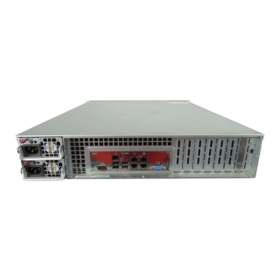
Chapter 1: Introduction Rear I/O Ports The color-coded I/O ports include one COM port, a VGA port, four USB 2.0 ports (additional USB headers are included on the serverboard) and four gigabit Ethernet ports. A dedicated IPMI LAN port is also included. Server Chassis Features The SC825TQ-R740LPB is an ATX form factor chassis designed to be used in a 2U rackmount confi... - Page 12 UPER ERVER 6027R-3RF4+ User's Manual Figure 1-1. Intel C600 Chipset: System Block Diagram Note: This is a general block diagram. Please see Chapter 5 for details.
-
Page 13: Contacting Supermicro
Super Micro Computer, Inc. 980 Rock Ave. San Jose, CA 95131 U.S.A. Tel: +1 (408) 503-8000 Fax: +1 (408) 503-8008 Email: marketing@supermicro.com (General Information) support@supermicro.com (Technical Support) Web Site: www.supermicro.com Europe Address: Super Micro Computer B.V. Het Sterrenbeeld 28, 5215 ML... - Page 14 UPER ERVER 6027R-3RF4+ User's Manual Notes...
-
Page 15: Chapter 2 Server Installation
Chapter 2: Server Installation Chapter 2 Server Installation Overview This chapter provides a quick setup checklist to get your SuperServer 6027R-3RF4+ up and running. Following these steps in the order given should enable you to have the system operational within a minimum amount of time. This quick setup assumes that your system has come to you with the processors and memory preinstalled. -
Page 16: Warnings And Precautions
UPER ERVER 6027R-3RF4+ User's Manual • This product is for installation only in a Restricted Access Location (dedicated equipment rooms, service closets and the like). • This product is not suitable for use with visual display work place devices acccording to §2 of the the German Ordinance for Work with Visual Display Units. Warnings and Precautions! Rack Precautions •... -
Page 17: Rack Mounting Considerations
Chapter 2: Server Installation Rack Mounting Considerations Ambient Operating Temperature If installed in a closed or multi-unit rack assembly, the ambient operating tempera- ture of the rack environment may be greater than the ambient temperature of the room. Therefore, consideration should be given to installing the equipment in an environment compatible with the manufacturer’s maximum rated ambient tempera- ture (Tmra). -
Page 18: Installing The System Into A Rack
UPER ERVER 6027R-3RF4+ User's Manual Installing the System into a Rack This section provides information on installing the SC825 chassis into a rack unit with the quick-release rails provided. There are a variety of rack units on the market, which may mean the assembly procedure will differ slightly. You should also refer to the installation instructions that came with the rack unit you are using. - Page 19 Chapter 2: Server Installation Figure 2-1: Separating the Rack Rails Separating the Inner and Outer Rails Rail Assembly 1. Locate the rail assembly in the chassis packaging. Extending the Rails 2. Extend the rail assembly by pulling it outward. 3. Press the quick-release tab. Quick- 4.
-
Page 20: Outer Rack Rails
UPER ERVER 6027R-3RF4+ User's Manual Figure 2-2. Assembling the Outer Rails Outer Rack Rails Outer rails attach to the rack and hold the chassis in place. The outer rails for the SC825 chassis extend between 30 inches and 33 inches. Installing the Outer Rails to the Rack 1. - Page 21 Chapter 2: Server Installation Figure 2-3. Installing the Rack Rails Installing the Chassis into a Rack 1. Extend the outer rails as illustrated above. 2. Align the inner rails of the chassis with the outer rails on the rack. 3. Slide the inner rails into the outer rails, keeping the pressure even on both sides.
- Page 22 UPER ERVER 6027R-3RF4+ User's Manual Notes...
-
Page 23: Chapter 3 System Interface
Chapter 3: System Interface Chapter 3 System Interface Overview There are several LEDs on the control panel as well as others on the drive carriers to keep you constantly informed of the overall status of the system and the activ- ity and health of specifi... -
Page 24: Control Panel Leds
SUPERSERVER 6027R-3RF4+ User's Manual Control Panel LEDs The control panel located on the front of the chassis has several LEDs. These LEDs provide you with critical information related to different parts of the system. This section explains what each LED indicates when illuminated and any corrective action you may need to take. -
Page 25: Drive Carrier Leds
Chapter 3: System Interface On the SuperServer 6027R-3RF4+, this LED indicates hard drive and/or DVD-ROM drive activity when fl ashing. Power Indicates power is being supplied to the system's power supply units. This LED should normally be illuminated when the system is operating. Drive Carrier LEDs Each drive carrier has two LEDs: SATA Drives... - Page 26 SUPERSERVER 6027R-3RF4+ User's Manual Notes...
-
Page 27: Chapter 4 Standardized Warning Statements For Ac Systems
The following statements are industry standard warnings, provided to warn the user of situations which have the potential for bodily injury. Should you have questions or experience difficulty, contact Supermicro's Technical Support department for assistance. Only certifi ed technicians should attempt to install or confi gure components. - Page 28 UPER ERVER 6027R-3RF4+ User's Manual Warnung WICHTIGE SICHERHEITSHINWEISE Dieses Warnsymbol bedeutet Gefahr. Sie befi nden sich in einer Situation, die zu Verletzungen führen kann. Machen Sie sich vor der Arbeit mit Geräten mit den Gefahren elektrischer Schaltungen und den üblichen Verfahren zur Vorbeugung vor Unfällen vertraut.
- Page 29 Warning Statements for AC Systems ﺟﺴﺪﻳﺔ ﺍﺻﺎﺑﺔ ﺗﺘﺴﺒﺐ ﻓﻲ ﺣﺎﻟﺔ ﻳﻤﻜﻦ ﺃﻥ ﺍﻧﻚ ﻓﻲ ﺧﻄﺮ ﻳﻌﻨﻲ ﻫﺬﺍ ﺍﻟﺮﻣﺰ !ﺗﺤﺬﻳﺮ ﺍﻟﺪﻭﺍﺋﺮ ﺑﺎﻟﻤﺨﺎﻁﺮ ﺍﻟﻨﺎﺟﻤﺔ ﻋﻦ ﻦ ﻋﻠﻰ ﻋﻠﻢ ، ﻛ ﻣﻌﺪﺍﺕ ﺗﻌﻤﻞ ﻋﻠﻰ ﺃﻱ ﻗﺒﻞ ﺃﻥ ﺍﻟﻜﻬﺮﺑﺎﺋﻴﺔ ﺣﻮﺍﺩﺙ ﺃﻱ ﻭﻗﻮﻉ ﻤﻨﻊ ﻟ ﺍﻟﻮﻗﺎﺋﻴﺔ...
-
Page 30: Installation Instructions
UPER ERVER 6027R-3RF4+ User's Manual Installation Instructions Warning! Read the installation instructions before connecting the system to the power source. 警告 将此系统连接电源前,请先阅读安装说明。 警告 將系統與電源連接前,請先閱讀安裝說明。 Warnung Vor dem Anschließen des Systems an die Stromquelle die Installationsanweisungen lesen. ¡Advertencia! Lea las instrucciones de instalación antes de conectar el sistema a la red de alimentación. -
Page 31: Circuit Breaker
Chapter 4: Warning Statements for AC Systems Circuit Breaker Warning! This product relies on the building's installation for short-circuit (overcurrent) protection. Ensure that the protective device is rated not greater than: 250 V, 20 A. 警告 此产品的短路(过载电流)保护由建筑物的供电系统提供,确保短路保护设备的额定电 流不大于250V,20A。 警告 此產品的短路(過載電流)保護由建築物的供電系統提供,確保短路保護設備的額定電 流不大於250V,20A。... -
Page 32: Power Disconnection Warning
UPER ERVER 6027R-3RF4+ User's Manual Waarschuwing Dit product is afhankelijk van de kortsluitbeveiliging (overspanning) van uw electrische installatie. Controleer of het beveiligde aparaat niet groter gedimensioneerd is dan 220V, 20A. Power Disconnection Warning Warning! The system must be disconnected from all sources of power and the power cord removed from the power supply module(s) before accessing the chassis interior to install or remove system components. - Page 33 Chapter 4: Warning Statements for AC Systems ¡Advertencia! El sistema debe ser disconnected de todas las fuentes de energía y del cable eléctrico quitado de los módulos de fuente de alimentación antes de tener acceso el interior del chasis para instalar o para quitar componentes de sistema. Attention Le système doit être débranché...
-
Page 34: Equipment Installation
UPER ERVER 6027R-3RF4+ User's Manual Equipment Installation Warning! Only trained and qualifi ed personnel should be allowed to install, replace, or service this equipment. 警告 只有经过培训且具有资格的人员才能进行此设备的安装、更换和维修。 警告 只有經過受訓且具資格人員才可安裝、更換與維修此設備。 Warnung Das Installieren, Ersetzen oder Bedienen dieser Ausrüstung sollte nur geschultem, qualifi ziertem Personal gestattet werden. ¡Advertencia! Solamente el personal califi... -
Page 35: Restricted Area
Chapter 4: Warning Statements for AC Systems Waarschuwing Deze apparatuur mag alleen worden geïnstalleerd, vervangen of hersteld door geschoold en gekwalifi ceerd personeel. Restricted Area Warning! This unit is intended for installation in restricted access areas. A restricted access area can be accessed only through the use of a special tool, lock and key, or other means of security. -
Page 36: Battery Handling
UPER ERVER 6027R-3RF4+ User's Manual אזור עם גישה מוגבלת !אזהרה יש להתקין את היחידה באזורים שיש בהם הגבלת גישה. הגישה ניתנת בעזרת .('כלי אבטחה בלבד )מפתח, מנעול וכד ﻣﺤﻈﻮﺭﺓ ﻣﻨﺎﻁﻖ ﻟﺘﺮﻛﻴﺒﻬﺎ ﻓﻲ ﻫﺬﻩ ﺍﻟﻮﺣﺪﺓ ﺗﺨﺼﻴﺺ ﺗﻢ ،ﺃﺩﺍﺓ ﺧﺎﺻﺔ ﻣﻦ ﺧﻼﻝ ﺍﺳﺘﺨﺪﺍﻡ ﻓﻘﻂ... - Page 37 Chapter 4: Warning Statements for AC Systems Warnung Bei Einsetzen einer falschen Batterie besteht Explosionsgefahr. Ersetzen Sie die Batterie nur durch den gleichen oder vom Hersteller empfohlenen Batterietyp. Entsorgen Sie die benutzten Batterien nach den Anweisungen des Herstellers. Attention Danger d'explosion si la pile n'est pas remplacée correctement. Ne la remplacer que par une pile de type semblable ou équivalent, recommandée par le fabricant.
-
Page 38: Redundant Power Supplies
UPER ERVER 6027R-3RF4+ User's Manual Redundant Power Supplies Warning! This unit might have more than one power supply connection. All connections must be removed to de-energize the unit. 警告 此部件连接的电源可能不止一个,必须将所有电源断开才能停止给该部件供电。 警告 此裝置連接的電源可能不只一個,必須切斷所有電源才能停止對該裝置的供電。 Warnung Dieses Gerät kann mehr als eine Stromzufuhr haben. Um sicherzustellen, dass der Einheit kein trom zugeführt wird, müssen alle Verbindungen entfernt werden. -
Page 39: Backplane Voltage
Chapter 4: Warning Statements for AC Systems ﺍﻣﺪﺍﺩ ﺍﻟﻄﺎﻗﺔ ﺑﻮﺣﺪﺍﺕ ﻋﺪﺓ ﺍﺗﺼﺎﻻﺕ ﺠﻬﺎﺯ ﺍﻟ ﻳﻜﻮﻥ ﻟﻬﺬﺍ ﻗﺪ ﺍﻟﻜﻬﺮﺑﺎء ﻋﻦ ﻮﺣﺪﺓ ﺍﻟ ﻟﻌﺰﻝ ﻛﺎﻓﺔ ﺍﻻﺗﺼﺎﻻﺕ ﻳﺠﺐ ﺇﺯﺍﻟﺔ Waarschuwing Deze eenheid kan meer dan één stroomtoevoeraansluiting bevatten. Alle aansluitingen dienen verwijderd te worden om het apparaat stroomloos te maken. Backplane Voltage Warning! Hazardous voltage or energy is present on the backplane when the system is... -
Page 40: Comply With Local And National Electrical Codes
UPER ERVER 6027R-3RF4+ User's Manual מתח בפנל האחורי !הרה אז קיימת סכנת מתח בפנל האחורי בזמן תפעול המערכת. יש להיזהר במהלך .העבודה ﺍﻟﻠﻮﺣﺔ ﺃﻭﺍﻟﻄﺎﻗﺔ ﺍﻟﻤﻮﺟﻮﺩﺓ ﻋﻠﻰ ﺍﻟﺘﻴﺎﺭ ﺍﻟﻜﻬﺮﺑﺎﺋﻲ ﻣﻦ ﺧﻄﺮ ﻫﻨﺎﻙ ﻫﺬﺍ ﺍﻟﺠﻬﺎﺯ ﺧﺪﻣﺔ ﻛﻦ ﺣﺬﺭﺍ ﻋﻨﺪ ﻳﻌﻤﻞ ﺍﻟﻨﻈﺎﻡ ﻋﻨﺪﻣﺎ ﻳﻜﻮﻥ Waarschuwing Een gevaarlijke spanning of energie is aanwezig op de backplane wanneer het systeem in gebruik is. -
Page 41: Product Disposal
Chapter 4: Warning Statements for AC Systems Attention L'équipement doit être installé conformément aux normes électriques nationales et locales. תיאום חוקי החשמל הארצי !אזהרה הציוד חייבת להיות תואמת לחוקי החשמל המקומיים והארציים התקנת ﺍﻟﻤﺘﻌﻠﻘﺔ ﺍﻟﻤﺤﻠﻴﺔ ﻭﺍﻟﻮﻁﻨﻴﺔ ﻘﻮﺍﻧﻴﻦ ﻳﺠﺐ ﺃﻥ ﻳﻤﺘﺜﻞ ﻟﻠ ﺍﻟﻜﻬﺮﺑﺎﺋﻴﺔ... -
Page 42: Hot Swap Fan Warning
UPER ERVER 6027R-3RF4+ User's Manual ¡Advertencia! Al deshacerse por completo de este producto debe seguir todas las leyes y reglamentos nacionales. Attention La mise au rebut ou le recyclage de ce produit sont généralement soumis à des lois et/ou directives de respect de l'environnement. Renseignez-vous auprès de l'organisme compétent. - Page 43 Chapter 4: Warning Statements for AC Systems 警告 當您從機架移除風扇裝置,風扇可能仍在轉動。小心不要將手指、螺絲起子和其他 物品太靠近風扇。 Warnung Die Lüfter drehen sich u. U. noch, wenn die Lüfterbaugruppe aus dem Chassis genommen wird. Halten Sie Finger, Schraubendreher und andere Gegenstände von den Öffnungen des Lüftergehäuses entfernt. ¡Advertencia! Los ventiladores podran dar vuelta cuando usted quite ell montaje del ventilador del chasis.
-
Page 44: Power Cable And Ac Adapter
fi re. Electrical Appliance and Material Safety Law prohibits the use of UL or CSA -certifi ed cables (that have UL/CSA shown on the code) for any other electrical devices than products designated by Supermicro only. 警告... - Page 45 Appareils électroménagers et de loi sur la sécurité Matériel interdit l'utilisation de UL ou CSA câbles certifi és qui ont UL ou CSA indiqué sur le code pour tous les autres appareils électriques que les produits désignés par Supermicro seulement.
- Page 46 UPER ERVER 6027R-3RF4+ User's Manual Notes 4-20...
-
Page 47: Chapter 5 Advanced Serverboard Setup
Chapter 5: Advanced Serverboard Setup Chapter 5 Advanced Serverboard Setup This chapter covers the steps required to install the X9DR3-LN4F+ serverboard into the chassis, connect the data and power cables and install add-on cards. All serverboard jumpers and connections are also described. A layout and quick refer- ence chart are included in this chapter for your reference. -
Page 48: Unpacking
UPER ERVER 6027R-3RF4+ User's Manual Unpacking The serverboard is shipped in antistatic packaging to avoid electrical static dis- charge. When unpacking the board, make sure the person handling it is static protected. Serverboard Installation This section explains the fi rst step of physically mounting the X9DR3-LN4F+ into the SC745TQ-R920B chassis. -
Page 49: Connecting Cables
Chapter 5: Advanced Serverboard Setup Connecting Cables Now that the serverboard is installed, the next step is to connect the cables to the board. These include the data cables for the peripherals and control panel and the power cables. Connecting Data Cables The cables used to transfer data from the peripheral devices have been carefully routed to prevent them from blocking the fl... -
Page 50: Rear I/O Ports
UPER ERVER 6027R-3RF4+ User's Manual Figure 5-1. Control Panel Header Pins Ground x (Key) x (Key) Power On LED 3.3V HDD LED ID/UID/SW/3.3V Stby NIC1 Link LED NIC1 Activity LED NIC2 Link LED NIC2 Activity LED OH/Fan Fail LED Red + (Blue Cathode Power Fail LED 3.3V Ground... -
Page 51: Installing The Processor And Heatsink
CPU socket cap is in place and none of the socket pins are bent; otherwise, contact your retailer immediately. • Refer to the Supermicro web site for updates on CPU support. Installing an LGA2011 Processor Press down on the lever labeled 'Close 1st' 1. - Page 52 UPER ERVER 6027R-3RF4+ User's Manual 3. With the lever labeled 'Close 1st' fully retracted, gently push down on the 'Open 1st' lever to open the load plate. Lift the load plate to open it completely. Gently push 4. Using your thumb and the index down to pop the load plate fi...
- Page 53 Chapter 5: Advanced Serverboard Setup Warning: You can only install the CPU to the socket in one direction. Make sure that the CPU is properly inserted into the socket before closing the load plate. If it doesn't close properly, do not force it as it may damage your CPU. Instead, open the load plate again and double-check that the CPU is aligned properly.
-
Page 54: Installing A Passive Cpu Heatsink
UPER ERVER 6027R-3RF4+ User's Manual Installing a Passive CPU Heatsink 1. Do not apply any thermal grease to the heatsink or the CPU die -- the re- quired amount has already been applied to the heatsink. 2. Place the heatsink on top of the CPU so that the four mounting holes are aligned with those on the Serverboard's and the Heatsink Bracket underneath. -
Page 55: Removing The Heatsink
Chapter 5: Advanced Serverboard Setup Removing the Heatsink Warning: We do not recommend that the CPU or the heatsink be removed. However, if you do need to uninstall the heatsink, please follow the instructions below to uninstall the heatsink to prevent damage done to the CPU or the CPU socket. 1. -
Page 56: Installing Memory
UPER ERVER 6027R-3RF4+ User's Manual Installing Memory Warning: Exercise extreme care when installing or removing DIMM modules to prevent any possible damage. Memory Support The X9DR3-LN4F+ supports up to 768 GB Registered (RDIMM), Load Reduced (LRDIMM), ECC or Unbuffered ECC/Non-ECC DDR3 800/1066/1333/1600 MHz in 24 DIMM slots. - Page 57 Chapter 5: Advanced Serverboard Setup DIMM Module Population Table Follow the table below when installing memory. Processors and their Corresponding Memory Modules CPU# Corresponding DIMMs CPU 1 P1-DIMM CPU2 P2-DIMM Processor and Memory Module Population Number of CPU and Memory Population Confi guration Table CPUs+DIMMs (*For memory to work properly, please follow the instructions below.) 1 CPU &...
- Page 58 1333 1333 Note: For detailed information on memory support and updates, please refer to the SMC Recommended Memory List posted on our website at http://www.supermicro.com/sup- port/resources/mem.cfm. Populating RDIMM (ECC) Memory Modules Intel E5-2600 Series Processor RDIMM Memory Support-Table Ranks Per...
-
Page 59: Adding Pci Add-On Cards
1066 1333 Note: For detailed information on memory support and updates, please refer to the SMC Recom- mended Memory List posted on our website at http://www.supermicro.com/support/resources/ mem.cfm. Other Important Notes and Restrictions • For the memory modules to work properly, please install DIMM modules of the same type, same speed and same operating frequency on the motherboard. -
Page 60: Serverboard Details
UPER ERVER 6027R-3RF4+ User's Manual Serverboard Details Figure 5-4. X9DR3-LN4F+ Layout FAN5 P2 DIMMG1 JPI2C1 JPW3 P2 DIMMG2 JPW1 JPW2 P1 DIMMA1 P2 DIMMG3 P2 DIMMH1 P1 DIMMA2 P1 DIMMA3 P2 DIMMH2 P2 DIMMH3 P1 DIMMB1 Alaways populate DIMMx1 first P1 DIMMB2 FAN6 P1 DIMMB3... -
Page 61: X9Dr3-Ln4F+ Quick Reference
Chapter 5: Advanced Serverboard Setup X9DR3-LN4F+ Quick Reference Jumper Description Default Setting JBT1 Clear CMOS See Section 5-10 C1/JI SMB to PCI-E Slots Pins 2-3 (Normal) XDP (Extended Debug Port) Open (Disabled) JPB1 BMC Enable/Disbable Pins 1-2 (Enabled) JPG1 VGA Enable/Disable Pins 1-2 (Enabled) JPL1 LAN1/LAN2 Enable/Disable... - Page 62 UPER ERVER 6027R-3RF4+ User's Manual JPW2/JPW3 12V 8-Pin Power Connectors JRK1 RAIDKey JSD1 SATA DOM (Device On Module) Power Connector JSTBY1 Standby Header JTPM1 TPM (Trusted Platform Module)/Port 80 LAN1/3, LAN2/4 G-bit Ethernet Ports 1/3, 2/4 (IPMI) LAN IPMI Dedicated LAN SAS 0~3, 4~7 Serial Attached SCSI Ports 0~3, 4~7 Onboard Buzzer (Internal Speaker)
-
Page 63: Connector Defi Nitions
Chapter 5: Advanced Serverboard Setup Connector Defi nitions ATX Power 24-pin Connector Pin Defi nitions Pin# Defi nition Pin # Defi nition Power Connectors +3.3V +3.3V -12V +3.3V A 24-pin main power supply connec- tor (JPW1) and two 8-pin CPU power PS_ON connectors (JPW2/3) must be con- nected to the power supply. - Page 64 UPER ERVER 6027R-3RF4+ User's Manual Power Fail LED PWR Fail LED The Power Fail LED connection is Pin Defi nitions (JF1) located on pins 5 and 6 of JF1. Refer Pin# Defi nition to p. 5-4 and the table on the right for pin defi...
- Page 65 Chapter 5: Advanced Serverboard Setup Power On LED Power LED Pin Defi nitions (JF1) The Power On LED connector is lo- Pin# Defi nition cated on pins 15 and 16 of JF1 (use 5V Stby JLED for a 3-pin connector). This Control connection is used to provide LED indication of power being supplied to...
- Page 66 UPER ERVER 6027R-3RF4+ User's Manual Chassis Intrusion Chassis Intrusion Pin Defi nitions The Chassis Intrusion header is des- Pin# Defi nition ignated JL1. Attach an appropriate Intrusion Input cable from the chassis to inform you Ground of a chassis intrusion when the chas- sis is opened Ethernet Ports Four Ethernet ports are located on the...
- Page 67 Chapter 5: Advanced Serverboard Setup Type A USB Ports Back Panel USB (USB9) (USB 0/1/2/3) Pin# Defi nition Pin# Defi nitions Universal Serial Bus (USB) Data- There are four Universal Serial Bus Data+ ports located on the I/O panel. In addi- Ground Ground tion, there is one Type A port and two...
- Page 68 UPER ERVER 6027R-3RF4+ User's Manual IPMB IPMB Header Pin Defi nitions A System Management Bus header Pin# Defi nition for IPMI 2.0 is located at IPMB. Con- Data nect the appropriate cable here to Ground use the IPMB I C connection on your Clock system.
- Page 69 Note: UID can also be triggered via IPMI. For more information on IPMI, please refer to the IPMI User's Guide posted on our Website @http://www.supermicro.com. Power SMB (I C) Connector PWR SMB Pin Defi...
-
Page 70: 5-10 Jumper Settings
UPER ERVER 6027R-3RF4+ User's Manual 5-10 Jumper Settings Explanation of Jumpers To modify the operation of the serverboard, jumpers can be used Connector to choose between optional settings. Pins Jumpers create shorts between two pins to change the function of the con- nector. - Page 71 Chapter 5: Advanced Serverboard Setup LAN Enable/Disable LAN Enable Jumper Settings JPL1 enables or disables the LAN Jumper Setting Defi nition ports on the serverboard. See the Enabled (default) table on the right for jumper settings. Disabled The default setting is Enabled. C Bus to PCI-Exp.
- Page 72 UPER ERVER 6027R-3RF4+ User's Manual Manufacturer's Mode Jumper JPME2 allows the user to ME Mode Select Jumper Settings flash the system firmware from a Jumper Setting Defi nition host server in order to modify system Pins 1-2 Manufacture's Mode settings. Close this jumper to bypass Pins 2-3 Normal (Default) SPI fl...
- Page 73 Chapter 5: Advanced Serverboard Setup Watch Dog Enable/Disable Jumper JWD controls the Watch Dog function. Watch Dog is a sys- tem monitor that can reboot the system when a software application hangs. Jumping pins 1-2 will cause Watch Dog WD to reset the system if an appli- Jumper Settings cation hangs.
-
Page 74: 5-11 Onboard Indicators
UPER ERVER 6027R-3RF4+ User's Manual 5-11 Onboard Indicators LAN LEDs The Ethernet ports (located beside the JLAN1/2 LED VGA port) have two LEDs. On each (Connection Speed Indicator) port, the yellow LED fl ashes to indi- LED Color Defi nition cate activity while the other LED may NC or 10 Mbps be green, amber or off to indicate the... -
Page 75: 5-12 Sata And Sas Ports
Chapter 5: Advanced Serverboard Setup 5-12 SATA and SAS Ports Serial ATA Ports SATA Port There are six Serial ATA Ports (I- Pin Defi nitions SATA0~I-SATA 5) located on the Pin# Defi nition Defi nition serverboard, including four SATA2 Ground ports and two SATA3 ports. -
Page 76: 5-12 Installing Software
UPER ERVER 6027R-3RF4+ User's Manual 5-12 Installing Software The Supermicro ftp site contains drivers and utilities for your system at ftp://ftp. supermicro.com. Some of these must be installed, such as the chipset driver. After accessing the ftp site, go into the CDR_Images directory and locate the ISO fi... -
Page 77: Superdoctor Iii
Chapter 5: Advanced Serverboard Setup SuperDoctor III The SuperDoctor® III program is a web-based management tool that supports remote management capability. It includes Remote and Local Management tools. The local management is called SD III Client. The SuperDoctor III program allows you to monitor the environment and operations of your system. -
Page 78: 5-13 Onboard Battery
ERVER 6027R-3RF4+ User's Manual Figure 5-7. SuperDoctor III Interface Display Screen (Remote Control) Note: The SuperDoctor III program and User’s Manual can be downloaded from the Supermicro web site at http://www.supermicro.com/products/accessories/soft- ware/SuperDoctorIII.cfm. For Linux, we recommend that you use the SuperDoctor II application instead. -
Page 79: Chapter 6 Advanced Chassis Setup
Chapter 6: Advanced Chassis Setup Chapter 6 Advanced Chassis Setup This chapter covers the steps required to install components and perform mainte- nance on the SC825TQ-R740LPB chassis. For component installation, follow the steps in the order given to eliminate the most common problems encountered. If some steps are unnecessary, skip ahead to the step that follows. -
Page 80: Control Panel
UPER ERVER 6027R-3RF4+ User's Manual Figure 6-1. Front and Rear Chassis Views 3.5" Drive Bays (2) DVD-ROM Drive (optional) USB Ports (2) COM Port Control Panel SAS/SATA Drives (8) System Reset Main Power Power Supplies Low-profi le PCI Slots Rear I/O Ports (see Section 5-4) Control Panel The control panel (located on the front of the chassis) must be connected to the JF1 connector on the serverboard to provide you with system status indications. -
Page 81: System Fans
Installing a New Fan 1. Replace the failed fan with an identical 8-cm, 12 volt fan (available from Supermicro). 2. Position the new fan into the space vacated by the failed fan previously re- moved. A "click" can be heard when the fan is fully installed in place and the power connections are made. -
Page 82: Drive Bay Installation/Removal
Proceed to the "DVD-ROM Installation" section later in this chapter for instructions. Warning! Enterprise level hard disk drives are recommended for use in Supermicro chassis and servers. For information on recommended HDDs, visit the Supermicro Web... -
Page 83: Sas/Sata Drive Installation
Chapter 6: Advanced Chassis Setup SAS/SATA Drive Installation These drives are mounted in carriers to simplify their installation and removal from the chassis. The carriers also help promote proper airfl ow for the drives. For this reason, even empty carriers without hard drives installed must remain in the chassis. Removing a Drive Carrier 1. -
Page 84: Hard Drive Backplane
UPER ERVER 6027R-3RF4+ User's Manual Figure 6-4. Mounting a Drive in a Carrier Warning: Use caution when working around the backplane. Do not touch the back- plane with any metal objects and make sure no ribbon cables touch the backplane or obstruct the holes, which aid in proper airfl... -
Page 85: Power Supply
The PWR Fail LED will illuminate and remain on until the failed unit has been replaced. Replace- ment units can be ordered directly from Supermicro (see contact information in the Preface). The power supply units have a hot-swap capability, meaning you can replace the failed unit without powering down the system. - Page 86 UPER ERVER 6027R-3RF4+ User's Manual Notes...
-
Page 87: Chapter 7 Bios
Chapter 7: BIOS Chapter 7 BIOS Introduction This chapter describes the AMI BIOS Setup utility for the X9DR3-LN4F+/X9DRi- LN4F+. It also provides the instructions on how to navigate the AMI BIOS Setup utility screens. The AMI ROM BIOS is stored in a Flash EEPROM and can be easily updated. -
Page 88: Starting The Setup Utility
UPER ERVER 6027R-3RF4+ User's Manual Note: For AMI UEFI BIOS Recovery, please refer to the UEFI BIOS Re- covery User Guide posted @http://www.supermicro.com/support/manuals/. Starting the Setup Utility Normally, the only visible Power-On Self-Test (POST) routine is the memory test. As the memory is being tested, press the <F2> key to enter the main menu of the AMI BIOS Setup utility. -
Page 89: Advanced Setup Confi Gurations
Chapter 7: BIOS System Time This item displays the system time in HH:MM:SS format (e.g. 15:32:52). Supermicro X9DRi-LN4+/X9DR3-LN4+ Version This item displays the SMC version of the BIOS ROM used in this system. Build Date This item displays the date that the BIOS Setup utility was built. - Page 90 UPER ERVER 6027R-3RF4+ User's Manual AddOn ROM Display Mode Use this item to set the display mode for the Option ROM. Select Keep Current to use the current AddOn ROM Display setting. Select Force BIOS to use the Option ROM display mode set by the system BIOS. The options are Force BIOS and Keep Current.
- Page 91 Chapter 7: BIOS CPU Confi guration This submenu displays the information of the CPU as detected by the BIOS. It also allows the user to confi guration CPU settings. Socket 1 CPU Information/Socket 2 CPU Information This submenu displays the following information regarding the CPUs installed in Socket 1/ Socket 2.
- Page 92 UPER ERVER 6027R-3RF4+ User's Manual Clock Spread Spectrum Select Enable to enable Clock Spectrum support, which will allow the BIOS to moni- tor and attempt to reduce the level of Electromagnetic Interference caused by the components whenever needed. The options are Disabled and Enabled. Hyper-threading Select Enabled to support Intel Hyper-threading Technology to enhance CPU per- formance.
- Page 93 Chapter 7: BIOS DCU IP Prefetcher Select Enabled for DCU (Data Cache Unit) IP Prefetcher support, which will prefetch IP addresses to improve network connectivity and system performance. The options are Enabled and Disabled. Intel® Virtualization Technology (Available when supported by the CPU) Select Enabled to support Intel Virtualization Technology, which will allow one platform to run multiple operating systems and applications in independent parti- tions, creating multiple "virtual"...
- Page 94 UPER ERVER 6027R-3RF4+ User's Manual CPU C3 Report (Available when Power Technology is set to Custom) Select Enabled to allow the BIOS to report the CPU C3 State (ACPI C2) to the operating system. During the CPU C3 State, the CPU clock generator is turned off.
-
Page 95: North Bridge
Chapter 7: BIOS Short Duration Power Limit This item displays the time period during which short duration power is main- tained. Chipset Confi guration North Bridge This feature allows the user to confi gure the settings for the Intel North Bridge. Integrated IO Confi... - Page 96 UPER ERVER 6027R-3RF4+ User's Manual CPU1 Slot3 PCI-E 3.0 x16 Link Speed This feature allows the user to set the PCI-Exp bus speed for the slot specifi ed above. The options are Gen1 (Generation 1), Gen2 and Gen3. CPU1 Slot1 PCI-E 3.0 x16 Link Speed This feature allows the user to set the PCI-Exp bus speed for the slot specifi...
- Page 97 Chapter 7: BIOS QPI Link Frequency Select Use this feature to select the desired QPI frequency. The options are Auto, 6.4 GT/s, 7.2 GT/s, and 8.0 GT/s. DIMM Confi guration This section displays the following DIMM information. Current Memory Mode This item displays the current memory mode.
- Page 98 UPER ERVER 6027R-3RF4+ User's Manual DDR Speed Use this feature to force a DDR3 memory module to run at a frequency other than what is specifi ed in the specifi cation. The options are Auto, Force DDR3- 800, Force DDR3-1066, Force DDR3-1333, Force DDR3-1600 and Force SPD. Channel Interleaving This feature selects from the different channel interleaving methods.
- Page 99 Chapter 7: BIOS South Bridge Confi guration This feature allows the user to confi gure the settings for the Intel PCH chip. PCH Information This feature displays the following PCH information. Name: This item displays the name of the PCH chip. Stepping: This item displays the status of the PCH stepping.
- Page 100 UPER ERVER 6027R-3RF4+ User's Manual SATA Mode Use this feature to confi gure SATA mode for a selected SATA port. The options are Disabled, IDE Mode, AHCI Mode and RAID Mode. The following are displayed depending on your selection: IDE Mode The following items are displayed when IDE Mode is selected: SATA (Serial-ATA) Controller 0~1 Use this feature to activate or deactivate the SATA controller, and set the...
- Page 101 Chapter 7: BIOS SCU (Storage Control Unit) Confi guration Storage Controller Unit Select Enabled to enable PCH SCU storage devices. The options are Disabled and Enabled. OnChip SCU Option ROM Select Enabled to support the onboard SCU Option ROM to boot up the system via a storage device.
- Page 102 UPER ERVER 6027R-3RF4+ User's Manual Maximum Read Request Select Auto to allow the system BIOS to automatically set the maximum Read Request size for a PCI-E device to enhance system performance. The options are Auto, 128 Bytes, 256 Bytes, 512 Bytes, 1024 Bytes, 2048 Bytes, and 4096 Bytes. ASPM Support This feature allows the user to set the Active State Power Management (ASPM) level for a PCI-E device.
- Page 103 Chapter 7: BIOS Super IO Confi guration Super IO Chip: This item displays the Super IO chip used in the motherboard. Serial Port 1 Confi guration Serial Port Select Enabled to enable a serial port specifi ed by the user. The options are En- abled and Disabled.
-
Page 104: Serial Port Console Redirection
UPER ERVER 6027R-3RF4+ User's Manual Serial Port Console Redirection • COM 1/COM 2 These two submenus allow the user to confi gure the following Console Redirection settings for a COM Port specifi ed by the user. Console Redirection Select Enabled to use a COM Port selected by the user for Console Redirection. The options are Enabled and Disabled. - Page 105 Chapter 7: BIOS Stop Bits A stop bit indicates the end of a serial data packet. Select 1 Stop Bit for standard serial data communication. Select 2 Stop Bits if slower devices are used. The options are 1 and 2. Flow Control This feature allows the user to set the fl...
- Page 106 UPER ERVER 6027R-3RF4+ User's Manual ACPI Setting Use this feature to confi gure Advanced Confi guration and Power Interface (ACPI) power management settings for your system. ACPI Sleep State Use this feature to select the ACPI State when the system is in sleep mode. Select S1 (CPU_Stop_Clock) to erase all CPU caches and stop executing instructions.
-
Page 107: Tpm Enable Status
Chapter 7: BIOS Pending Operation: This item displays the status of a pending operation. Current Status Information: This item displays the information regarding the current TPM status. TPM Enable Status This item displays the status of TPM Support to indicate if TPM is currently enabled or disabled. - Page 108 UPER ERVER 6027R-3RF4+ User's Manual Intel ME Subsystem Confi guration This feature displays the following ME Subsystem Confi guration settings. • ME BIOS Interface Version • ME Version iSCSI Confi guration: This item displays iSCSI confi guration information: iSCSI Initiator Name: This item displays the name of the iSCSI Initiator, which is a unique name used in the world.
-
Page 109: Event Logs
Chapter 7: BIOS Event Logs Use this feature to confi gure Event Log settings. Change SMBIOS Event Log Settings This feature allows the user to confi gure SMBIOS Event settings. Enabling/Disabling Options SMBIOS Event Log Select Enabled to enable SMBIOS (System Management BIOS) Event Logging during system boot. - Page 110 UPER ERVER 6027R-3RF4+ User's Manual Erasing Settings Erase Event Log Select Enabled to erase the SMBIOS (System Management BIOS) Event Log, which is completed before a event logging is initialized upon system reboot. The options are No and Yes. When Log is Full Select Erase Immediately to immediately erase SMBIOS error event logs that ex- ceed the limit when the SMBIOS event log is full.
-
Page 111: Ipmi
Chapter 7: BIOS IPMI Use this feature to confi gure Intelligent Platform Management Interface (IPMI) settings. IPMI Firmware Revision This item indicates the IPMI fi rmware revision used in your system. IPMI Status This item indicates the status of the IPMI fi rmware installed in your system. ... - Page 112 UPER ERVER 6027R-3RF4+ User's Manual When SEL is Full This feature allows the user to decide what the BIOS should do when the system event log is full. Select Erase Immediately to erase all events in the log when the system event log is full.
-
Page 113: Boot
Chapter 7: BIOS Gateway IP Address This item displays the Gateway IP address for this computer. This should be in decimal and in dotted quad form (i.e., 192.168.10.253). Boot This submenu allows the user to confi gure the following boot settings for the system. -
Page 114: Security
UPER ERVER 6027R-3RF4+ User's Manual Network Devices Boot Option #1 This item displays the fi rst boot device. Delete Boot Options Delete Boot Option This item allows the user to select a boot device to delete from the boot priority list. -
Page 115: Save & Exit
Chapter 7: BIOS Save & Exit This submenu allows the user to confi gure the Save and Exit settings for the system. Discard Changes and Exit Select this option to quit the BIOS Setup without making any permanent changes to the system confi guration, and reboot the computer. Select Discard Changes and Exit, and press <Enter>. - Page 116 UPER ERVER 6027R-3RF4+ User's Manual Discard Changes Select this feature and press <Enter> to discard all the changes and return to the BIOS setup. When the dialog box appears, asking you if you want to load previ- ous values, click Yes to load the values previous saved, or click No to keep the changes you've made so far.
-
Page 117: Appendix A Bios Error Beep Codes
Appendix A: BIOS Error Beep Codes Appendix A BIOS Error Beep Codes During the POST (Power-On Self-Test) routines, which are performed at each system boot, errors may occur. Non-fatal errors are those which, in most cases, allow the system to continue to boot. - Page 118 UPER ERVER 6027R-3RF4+ User's Manual Notes...
-
Page 119: Appendix B System Specifi Cations
Appendix B: System Specifi cations Appendix B System Specifi cations Processors Single or dual Intel® Xeon E5-2600 Series processors Note: Please refer to our web site for a complete listing of supported processors. Chipset Intel C600 chipset BIOS 32 Mb AMI® SPI Flash ROM Memory Capacity Twenty-four DIMM sockets supporting up to 768 GB Registered (RDIMM), Load Reduced (LRDIMM), ECC or Unbuffered ECC/Non-ECC DDR3 800/1066/1333/1600... - Page 120 UPER ERVER 6027R-3RF4+ User's Manual Weight Gross (Bare Bone): 57 lbs. (25.9 kg.) System Cooling Three 8-cm system cooling fans System Input Requirements AC Input Voltage: 100 - 240V AC auto-range Rated Input Current: 13 - 4A max Rated Input Frequency: 50 to 60 Hz Power Supply Rated Output Power: 740W (Part# PWS-741P-1R) Rated Output Voltages: +12V (61.7A), +5Vsb (4A)
- Page 121 Appendix B: System Specifi cations Notes...
- Page 122 ERVER 6027R-3RF4+ User's Manual (continued from front) The products sold by Supermicro are not intended for and will not be used in life support systems, medical equipment, nuclear facilities or systems, aircraft, aircraft devices, aircraft/emergency com- munication devices or other critical systems whose failure to perform be reasonably expected to result in signifi...
Need help?
Do you have a question about the SuperServer 6027R-3RF4+ and is the answer not in the manual?
Questions and answers