Table of Contents
Advertisement
Quick Links
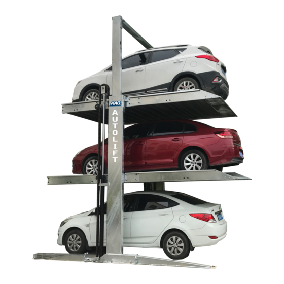
3 Car Stacker
AutoLift - PP609
2 Post 3 Car Stacker
2000Kg Lifting Capacity per platform
Note: While all due care and attention has been taken in the preparation of this document, Advance AutoQuip shall not be liable for any inaccuracies or omissions
Ph: 08 9279 1663 | Fax: 08 9279 1667 | E: sales@aaq.net.au | W: www.aaq.net.au
INSTALLATION MANUAL & OPERATION
INSTRUCTIONS
- READ THE ENTIRE CONTENTS OF THIS MANUAL BEFORE
INSTALLATION AND OPERATION. BY PROCEEDING YOU AGREE THAT
YOU FULLY UNDERSTAND AND COMPREHEND THE FULL CONTENTS
OF THIS MANUAL. FORWARD THIS MANUAL TO ALL OPERATORS.
FAILURE TO OPERATE THIS EQUIPMENT AS DIRECTED MAY CAUSE
Specifications subject to change without notice.
which may occur therein
Advance AutoQuip
2 McDonald Crescent | Bassendean WA 6054
INJURY OR DEATH.
READ FIRST
DO NOT use the
machine until you read
and understand all the
dangers, warnings and
cautions in this manual.
Advertisement
Table of Contents

Related Manuals for AAQ AutoLift PP609


Summary of Contents for AAQ AutoLift PP609
- Page 1 Note: While all due care and attention has been taken in the preparation of this document, Advance AutoQuip shall not be liable for any inaccuracies or omissions which may occur therein Advance AutoQuip 2 McDonald Crescent | Bassendean WA 6054 Ph: 08 9279 1663 | Fax: 08 9279 1667 | E: sales@aaq.net.au | W: www.aaq.net.au...
-
Page 2: Table Of Contents
Catalogue 1.Introduce........................ 3 1.1 Summarize..................... 3 1.2 Statement....................... 3 2. Equipment introduction...................4 2.1 Equipment description................4 2.2 Equipment parameter...................4 3.Equipment transportation..................4 4.Assemble the lift ..................... 5 4.1 Notice......................5 4.2Layout of the equipment ................6 4.3Tools for installing equipment:..............7 4.4Installation procedure:................ -
Page 3: Introduce
1.Introduce 1.1 Summarize The DTPP609 is a two-column hydraulic parking system. This manual should be read carefully before installing and assembling equipment, which helps to assemble and use the equipment in the right way to avoid risks and increase the reliability and service life of the equipment. The operator should follow the instructions in this manual, otherwise the user will be responsible for any loss and personal injury. -
Page 4: Equipment Introduction
2.Equipment introduction 2.1 Equipment description The DTPP609 is a hydraulic parking lift with three parking spaces for two parking plates. This lift has the advantages of simple structure, convenient assembly and space saving, and is well received by users. This lift is mainly composed of two side columns and a wave plate platform. -
Page 5: Assemble The Lift
4.Assemble the lift 4.1 Notice 4.1.1 Read and understand the equipemt's safety alerts before using the equipment. 4.1.2 Pay attention to protect your hands and feet. The hands and feet must be removed from the rotating parts. When the equipment falls, remove the feet to avoid being crushed. ... -
Page 6: Layout Of The Equipment
4.1.16 Always check for damaged parts and check their activity and synchronization. If any parts are not working properly, please do not use the equipment. Warning! 4.1.17 The work area should be non-flammable because there is an electric spark when the switch is working. -
Page 7: Tools For Installing Equipment
4.3 Tools for installing equipment Hammer, level, open end wrench, hex wrench, adjustable wrench, crowbar, chalk or colored pen, flat head screwdriver, tape measure (5 m), needle-nosed pliers, etc. 4.4 Installation procedure : FIG1 .Down position schematic... - Page 8 FIG2 Up position schematic...
- Page 9 4.4.1Column front leg and additional plate install Column Front leg additional plate M16*50outer hexagon bolt 10pcs M16 nut 10pcs Ø16 plain washers 10pcs Ø16 spring washer 10 pcs FIG 3 Column front leg and additional plate installation diagram 4.4.2 Move the Stage 1 and Stage 2 carriage to the distance shown in Figure 4 and support them with wooden or steel tubes of appropriate height to prevent the carriage from falling.
- Page 10 Stage 2 carriage 1000 500m Stage 1 carriage FIG4 Cariage movement diagram 4.4.3Foundation diagram FIG 5 Foundation diagram...
- Page 11 4.4.4Column fixing and stage 1 carriage support tube installation tube stage 1 carriage support Here, Use 16 pieces of M12*35 hex bolts, M12 nut, Ø12 flat washer, Ø12 spring washer. Note: The bolts are worn from the outside to the inside.
- Page 12 beam Up platfrom rear beam Lower platfrom rear Up platform left beam beam Lower platfrom left Up platfrom Lower platfrom left beam pull rod ramp Up platfrom Up platfrom right beam ramp lower platfrom beam Lower platfrom right FIG 7 Platfrom frame Installation diagram M16*45 hex bolt, M16 nut Φ...
- Page 13 M16X110 hex bolt, M16 M16X45 hex bolt, M16 nut Φ16 flat washer, M8*20 bolt, nut Φ16 flat washer, spring washer, bolts self-tightening nut Φ spring washer, bolts worn from 8 flat washer are worn from inside outside to the inside. FIG 10 side beam Installation diagram FIG11 wave plate Installation diagram FIG 12 1 level platfrom Installation completion diagram...
- Page 14 Balance axis FIG 13 2-layer plate balance shaft installation diagram Hexagon socket head screw M8*20 Balance sprocket FIG14 2-layer plate balance shaft installation diagram...
- Page 15 Hexagon socket head screw M8*20 FIG15 2-layer plate balance shaft installation diagram FIG16 Plate diagram...
- Page 16 4.4.6 Cylinder and chain installation Chain clip Cylinder FIG17 Cylinder Installation Diagram Cylinder Cylinder fixing bolt、M8 nut FIG 18 Cylinder fixing diagram...
- Page 17 Lifting sprocket guard Lifting sprocket Cross countersunk head bolt M5*12 FIG19 Lifting sprocket installation Diagram Note: Install the lifting sprocket guard after the chain is installed. After above cylinders and other components are installed, start to install chain. Cylinder Chain Balance sprocket FIG20 Chain Installation...
- Page 18 Chain Clip FIG22 Chain Installation Chain FIG23 Chain wrapping diagram...
- Page 19 Chain plate seat, Hex bolts M10*30, Ø10 flat gasket, Spring washer FIG 24 Chain plate seat installation Diagram : When the same tooth on both sides of the balance sprocket is hung on Chain balance adjustment the same chain, the device is in equilibrium. ...
- Page 20 Anti-dropper joined cover Right Column Limit Switch Anti-Dropper M16*65 Hex bolts, Ø16 flat gasket, spring washer FIG 26 Right column anti-dropper installation diagram Note: The installation procedure of the right column anti-dropper is to first place the limit switch on the anti-dropper joint shield, and then fix the anti-dropper on the column. The limit switch mounting is fixed by 4 cross countersunk head bolts M5*12.
- Page 21 4.4.8 Control arm installation, Please fix the control arm according to the foundation drawing. Control Arm M8*80 Expansion bolt FIG28 Control Arm Installation diagram 4.4.9 Tubing connection,connect the 1 & 2 with T joint, connect the other side of the tube to power unit.
-
Page 22: Control Principle
4.4.10 Installation and commissioning Note : When in the process of lifting, observe all the operating parts, check the correctness of the installation and commissioning, only when you confirm that there are no errors, you can finally start lifting ... -
Page 23: Control Problem
5.3 Control Problem Appearance Possible reasons Exclusion method power cord Check the line circuit and confirm connected that the line is connected correctly. No response when turning the key switch Emergency stop switch is Rotate the emergency stop switch to pressed reset it The plate cannot rise when... -
Page 24: Electrical Schematic
6. Electrical schematic FIG 30 7. Hydraulic schematic FIG31... -
Page 30: Precautions For Use
8.Precautions for use 8.1 Announcements 8.1.1 If the equipment is not used for a long time, the main power supply should be turned off to avoid accidents and energy saving. 8.1.2 If the equipment has not been used for a long time, please lubricate it before re-use to check for any damage and rust. -
Page 31: Take Cars
8.2.1 Drive the vehicle to the appropriate position on the boarding platform, avoid collision with the side beams of the platform, and perform manual braking. 8.2.2 The key switch turns to the UP1 position, the upper platform rises, and after hitting the 1st limit switch, the platform stops rising. - Page 32 9.1 Check if the power supply, line, etc. are working properly. 9.2 Check if the chain, chain pin, split pin, etc. can work normally. 9.3 Check if the expansion bolt is loose. If the expansion bolt is loose, it should be tightened. ...
- Page 33 Joint damage Replacement joint Cylinder oil leakage Cylinder seal damage Replace the seal of the cylinder Replace the motor and confirm that the power Motor burned supply is correct Motor does not work Check and confirm that the voltage is a stable Voltage is too low voltage The fuse is burned...
- Page 34 SAFETY OPERATING PROCEDURES Vehicle Hoist DO NOT use this machine unless the operator has been thoroughly instructed in its safe use and operation. Safety glasses must be worn at all Long and loose hair must be times in work areas. contained.
- Page 35 THIS WARRANTY SUPERSEDES ALL OTHER WARRANTY POLICIES PREVIOUSLY STATED AND IN ALL OTHER ADVANCE AUTOQUIP’s PRODUCT SPECIFIC LITERATURE. Advance AutoQuip 2 McDonald Crescent | Bassendean WA 6054 Ph: 08 9279 1663 | Fax: 08 9279 1667 | E: sales@aaq.net.au | W: www.aaq.net.au...
- Page 36 COMMISSIONING REPORT 1. Details of Customer Customer Name: Installation Address: 2. Hoist Details Model No: 2 McDonald Crescent Hoist Type: Bassendean WA 6054 Installation Date: P: 08 9279 1663 | E: sales@aaq.net.au 3. Commissioning Report Comments Safety Devices Safety devices incorporated into the design of the vehicle to AS/NZS 1418.9 Welds Visual check all welds completed and comply to requirement of AS/NZS 1554 Hydraulic Equipment and Controls Visual check carried out for leaks Pneumatic Equipment and Controls Visual check carried out for leaks Safety Locks Safety locks tested for correct operation Support Pads Checked for good working order Wheel Stops Supplied with the hoist and in good working order Hoist Motion Limits Checked for correct operation Load Test and Speed Check Hoist checked with load for correct operation and speed control tested Wire Ropes Checked wire ropes for correct installation and tension Concrete Floor Concrete floor is a suitable depth for installation...
- Page 37 COMMISSIONING REPORT Location of Vehicle Hoist & Vehicle Clearances Vehicle hoist or any part of the load is positioned no less than 600mm away from any fixed structure Provisions have been made for effective clearances above the vehicle when the hoist is in its fully raised position. Markings ‐ Hoist Checked for Relevant Marking Including: Make & Model Number Serial number Rated Capacity Reference to maintenance Operation instructions Screw and Nut Gaps Hoist compliance plate showing design registration Functional Test Vehicle hoist has been tested and all safety devices, limit switches and control function interlocks have been tested for correct operation. Demonstration The installer has demonstrated the operation of the vehicle hoist to the owner or operator Electrical Equipment and Controls Lock off isolating switch installed Emergency stop button installed 3. Details of Electrical Contractor Trading Name: EC Licence Number: Address: Telephone Number: 4. Signature Name: ___________________________________________________________ Date: I, being the person responsible for completing the commissioning report have exercised reasonable skill and competency when completing the report and herby certify that the vehicle hoist has been commissioned fit for use as per the Australian / New Zealand Standard 1418.9:1996 Vehicle Hoists.
Need help?
Do you have a question about the AutoLift PP609 and is the answer not in the manual?
Questions and answers