Advertisement
Quick Links
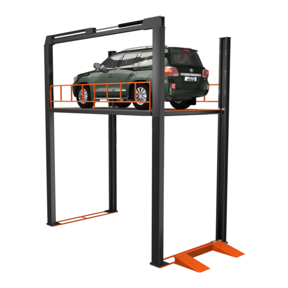
PARKING HOIST
AutoLift FP-VRC
Four Post Vertical Reciprocating Conveyor
Lifting Capacity - Varies (see specific product specifications)
Design Registration Approval Number: N/A
Design Code: AS1418.9-1996
Note: While all due care and attention has been taken in the preparation of this document, Advance AutoQuip shall not be liable for any inaccuracies or omissions
INSTALLATION MANUAL & OPERATION
INSTRUCTIONS
- READ THE ENTIRE CONTENTS OF THIS MANUAL BEFORE
INSTALLATION AND OPERATION. BY PROCEEDING YOU AGREE THAT
YOU FULLY UNDERSTAND AND COMPREHEND THE FULL CONTENTS
OF THIS MANUAL. FORWARD THIS MANUAL TO ALL OPERATORS.
FAILURE TO OPERATE THIS EQUIPMENT AS DIRECTED MAY CAUSE
Specifications subject to change without notice.
2 McDonald Crescent | Bassendean WA 6054
Ph: 08 9279 1663 | Fax: 08 9279 1667 | E: sales@aaq.net.au | W: www.aaq.net.au
INJURY OR DEATH.
which may occur therein
Advance AutoQuip
READ FIRST
DO NOT use the
machine until you read
and understand all the
dangers, warnings and
cautions in this manual.
Advertisement

Subscribe to Our Youtube Channel
Related Manuals for AAQ AutoLift FP-VRC


Summary of Contents for AAQ AutoLift FP-VRC
- Page 1 Note: While all due care and attention has been taken in the preparation of this document, Advance AutoQuip shall not be liable for any inaccuracies or omissions which may occur therein Advance AutoQuip 2 McDonald Crescent | Bassendean WA 6054 Ph: 08 9279 1663 | Fax: 08 9279 1667 | E: sales@aaq.net.au | W: www.aaq.net.au...
-
Page 2: Foundation Preparation
1. Foundation preparation Before starting installation, please check the following conformities: 1) The hoist way / shaft size is strictly as per dimensions showed in the drawing made by Advance AutoQuip upon ordering; 2) Please make job site clear from any obstacles that may interfere or hazard the installation process. - Page 3 3. Assembly Process 3.1. Main Parts of FPVRC 1. Post No.1 2. Post No.2 3. Post No.3 4. Post No. 4 5. Connecting Beam 6. Carriage 7. Base plate 8. Platform 9. Ramp 10. Side Beam 11. Main Beam 12. Cylinder 13.
- Page 5 3.2. Assembly of main structure 3.2.1. Place Base Plate (2 pcs, front & rear) in position on ground 3.2.2. Put Carriage onto the Base Plates and place head side of Carriages on the side of Post No. 2&3. Head Side (with Chain Joint) Tail Side (with Roller) 3.2.3.
- Page 6 3.2.4. Erect 4 posts one by one and bolt with Base Plate. Post No. 2 & 3 have chain joint base like below; which is not available for No. 1 & 4 Front sides of Post No. 3&4 and Rear sides of Post No. 1&2 have anti- falling locks like below: 3.2.5.
- Page 7 3.2.7. Connect Post No. 1 & 4 with Side Beam 3.2.8. Install Main Beam on Post No. 2 & 3 as per reserved holes for bolting. 3.2.9. Install Cylinder onto Main Beam (horizontal installation) or along the Post No.2 (vertical installation). For details, please turn to Fig 1 & 2 Installation of Cylinder. 3.2.10.
- Page 8 (Pneumatic Valve) (Tee Joint) Four pcs of Pneumatic Cylinders are equipped on each stopping level (except ground level), one piece on each post. Like attached photos. Tee Joint is for air hoses to split air flow.
- Page 9 Note: the black hose with Tee joint is air hose for pneumatic cylinder 3.6. Electrical wiring & diagram Please refer to Electrical Diagram in the end of this manual.
- Page 15 I > 380V/24V 220V/24V SB0-1 SQ2-5 GENERAL LAYOUT Drawing: Project: N.M. N.A. Country: Date: 05-08-2021 Model: FP-VRC Lifting Capacity: 3500kg Cover Area: 6000*3400mm Limit SQ to normally open Platform size: 5950*3350mm Total Travel: 4900mm Ramp: H200mm Limit SQ1: 12 Safety valve: 0 Pump motor: 4Kw Lifting Speed: 4mts/min Safety SQ : 16...
- Page 16 SAFETY OPERATING PROCEDURES Vehicle Hoist DO NOT use this machine unless the operator has been thoroughly instructed in its safe use and operation. Safety glasses must be worn at all Long and loose hair must be times in work areas. contained.
-
Page 17: Commissioning Report
COMMISSIONING REPORT 1. Details of Customer Customer Name: Installation Address: 2. Hoist Details Model No: 2 McDonald Crescent Hoist Type: Bassendean WA 6054 Installation Date: P: 08 9279 1663 | E: sales@aaq.net.au 3. Commissioning Report Comments Safety Devices Safety devices incorporated into the design of the vehicle to AS/NZS 1418.9 Welds Visual check all welds completed and comply to requirement of AS/NZS 1554 Hydraulic Equipment and Controls Visual check carried out for leaks Pneumatic Equipment and Controls Visual check carried out for leaks Safety Locks Safety locks tested for correct operation Support Pads Checked for good working order Wheel Stops Supplied with the hoist and in good working order Hoist Motion Limits Checked for correct operation Load Test and Speed Check Hoist checked with load for correct operation and speed control tested Wire Ropes Checked wire ropes for correct installation and tension Concrete Floor Concrete floor is a suitable depth for installation... - Page 18 COMMISSIONING REPORT Location of Vehicle Hoist & Vehicle Clearances Vehicle hoist or any part of the load is positioned no less than 600mm away from any fixed structure Provisions have been made for effective clearances above the vehicle when the hoist is in its fully raised position. Markings ‐ Hoist Checked for Relevant Marking Including: Make & Model Number Serial number Rated Capacity Reference to maintenance Operation instructions Screw and Nut Gaps Hoist compliance plate showing design registration Functional Test Vehicle hoist has been tested and all safety devices, limit switches and control function interlocks have been tested for correct operation. Demonstration The installer has demonstrated the operation of the vehicle hoist to the owner or operator Electrical Equipment and Controls Lock off isolating switch installed Emergency stop button installed 3. Details of Electrical Contractor Trading Name: EC Licence Number: Address: Telephone Number: 4. Signature Name: ___________________________________________________________ Date: I, being the person responsible for completing the commissioning report have exercised reasonable skill and competency when completing the report and herby certify that the vehicle hoist has been commissioned fit for use as per the Australian / New Zealand Standard 1418.9:1996 Vehicle Hoists.
Need help?
Do you have a question about the AutoLift FP-VRC and is the answer not in the manual?
Questions and answers