Table of Contents
Advertisement
Operation manual
ECO GOLD
Heating and cooling thermostats with control head GOLD
Immersion thermostat
ECO GOLD
Heating thermostats
E 4 G, E 10 G, E 20 G, E 25 G, E 40 G, ET 6 G, ET 12 G, ET 15 G, ET 20 G
Cooling thermostats
RE 415 G, RE 415 GW, RE 420 G, RE 630 G, RE 1225 G, RE 2025 G, RE 1050 G
Viscothermostats
Viscotemp 15 G, Viscotemp 18 G, Viscotemp 24 G, Viscotemp 40 G
Calibration thermostat
RE J 1225 G
Version 09/2021 k
Read the instructions before starting work!
Advertisement
Table of Contents

Related Manuals for Lauda Viscotemp 15 G


Summary of Contents for Lauda Viscotemp 15 G
- Page 1 RE 415 G, RE 415 GW, RE 420 G, RE 630 G, RE 1225 G, RE 2025 G, RE 1050 G Viscothermostats Viscotemp 15 G, Viscotemp 18 G, Viscotemp 24 G, Viscotemp 40 G Calibration thermostat RE J 1225 G...
- Page 2 Manufacturer LAUDA DR. R. WOBSER GMBH & CO. KG Laudaplatz 1 97922 Lauda-Königshofen Germany Phone: +49 (0)9343 503-0 Fax: +49 (0)9343 503-222 E-mail info@lauda.de Internet http://www.lauda.de Translation of the original operation manual YACE0088 replaces version 10/2019 j, 05/2019 h, 11/2018 g, 05/2017 f, 04/2017 e, 11/2016 d1, 08/2016 a3, 08/2011 a2,...
-
Page 3: Table Of Contents
Table of contents Safety ....................................... 7 Safety information ................................. 7 General safety ..................................8 Special safety information ..............................9 General remarks ................................... 11 Description of the device ..............................11 Intended application................................11 Use other than that intended ............................. 11 Responsibility of the operating body - safety information ....................11 Materials .................................... - Page 4 Disposal of the refrigerant ............................62 8.5.2 Disposal of the packaging ............................62 Taking the device out of service ............................63 Ordering replacement parts / LAUDA Service ........................ 64 Accessories ....................................65 10 Technical data and graphs ................................67 11 Declaration of Conformity ................................. 77 12 Index ......................................
- Page 5 13.2 Setting the volume of the acoustic signals ........................87 13.3 Setting the chiller ................................87 13.4 Setting the display brightness ............................88 13.5 Defining the starting mode (Autostart) ..........................88 13.6 Limiting the mains current consumption .......................... 89 13.7 Entering the offset of the displayed temperature (calibration) ..................89 13.8 Restoring the factory setting of the internal temperature sensor ..................
- Page 6 19.6.3 Connecting the thermostat to the PC ........................118 19.6.4 Where is the ECO Virtual COM Port? ........................ 120 19.7 Commands and error messages applicable to the RS 232/485 interface module and to the Ethernet interface 122 19.7.1 Interface write commands (data issued to the thermostat) ................122 19.7.2 Interface read commands ............................
-
Page 7: Safety
Safety Safety information Type and source Consequences of non-compliance Action 1 Action ... Danger! "DANGER" indicates an immediate dangerous situation which – if the safety requirements are ignored – may result in fatal or severe, irreversible injuries. Type and source Consequences of non-compliance Action 1 ... -
Page 8: General Safety
General safety Read through the operating instructions carefully. They contain important information for working with this device. If you have any queries, please contact our Service Department ( 8.7). Follow all the directions in these operating instructions. Only in this way is the correct procedure ensured when working with the device. -
Page 9: Special Safety Information
Instructions for Class A digital device, USA: “Note: This equipment has been tested and found to comply with the limits for Class A digital device, pursuant to Part 15 of the FCC (Federal Communication Commission) Rules. These limits are designed to provide reasonable protection against harmful interference when the equipment is operated in a commercial environment. - Page 10 Use the cooling coil with cooling water only at operating temperatures below 100 °C. At higher temperatures there is danger of hot vapors forming. Have repairs carried out only by specialists. Keep to all the service and maintenance intervals ( 8.3.2). ...
-
Page 11: General Remarks
"cooling thermostat", which is used for cooling and heating liquids. Intended application This LAUDA thermostat is manufactured exclusively for cooling/heating liquid baths. In the case of the immersion thermostat the baths used must have methods of secure mounting. The device may only be put into operation in suitable interior rooms. -
Page 12: Materials
Materials All parts that are exposed to heat transfer liquid are manufactured from high-quality materials adapted to withstand the operating temperature. High-quality stainless steel, brass, bronze, high-quality heat-resistant plastics and elas- tomers are used. 12 / 134 ECO Gold 09/2021... -
Page 13: Device Description
Device types Heating thermostats The type designation of the LAUDA heating thermostats is composed of the prefix E for ECO, the approximate bath volume in liters and a G for the GOLD device variant. Example: E 10 G is a heating thermostat with a maximum bath volume of 10 liters in the GOLD device variant. -
Page 14: Interface Modules (Accessories)
The following modules are currently available: 1. Analogue Module (LAUDA catalogue no. LRZ 912) with two inputs and two outputs on a six-pole DIN socket. The inputs and outputs can be set independently of one another as a 0 - 20 mA, 4 – 20 mA or 0 –... -
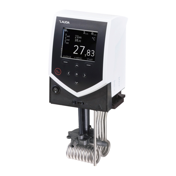
Page 15: Operating And Functional Controls
Operating and functional controls On the following pages the ECO GOLD control head, the control panel and the heating/cooling thermostat device types are presented. Control Head ECO GOLD (can be used as immersion thermostat with screw clamp) Light sensor for automatic control of display brightness Color TFT display Control panel (refer to following page) Mains switch... - Page 16 Control panel and display ECO GOLD Display Control panel Expanded status display Soft keys, left and right Status display Enter key Display of the internal or external tempera- Cursor keys (cursor keys) for Up, Down, Left ture value (T or T and Right.
- Page 17 Rear view of Control Head ECO GOLD USB interface Upper module receptacle approx. 51 mm x 27 mm for analogue, RS 232/485 module, Profibus module and contact modules. Lower module receptacle approx. 51 mm x17 mm for Pt100/LiBus module Connection 75S for control cable of cooling underpart for RE 1050 G Rating label Connection socket 51H for power supply between the control head and cooling underpart Mains connecting lead...
- Page 18 Heating Thermostats ECO GOLD Cooling coil connections Pump connection: outflow and return (as standard only with E 4 G and ET 15 G) Four feet Mains connecting lead Rating label Bath draining tap Bath drain point 18 / 134 ECO Gold 09/2021...
- Page 19 Viscothermostat Viscotemp 24 G Pump connector set with thread connection M16 x 1 (concealed) Recessed grips (right and left) Viscotemp 24 cover plate (LCZ 0734) Bath with glass windows Drain tap and draining nozzle (right side) Type plate (right side) Four feet (concealed) 19 / 13 4 09/2021...
- Page 20 Cooling Thermostats ECO GOLD Pump connection: Outflow and return with M16 x 1 thread (stainless steel) Bath cover Front grip recess Ventilation grill (both sides) Front panel (removable without tools) Four feet 20 / 134 ECO Gold 09/2021...
- Page 21 Rating label Control cable between the control head and cooling underpart (only with RE 1050 G) Rear grip recess Connecting lead between the control head and cooling underpart Bath draining tap Bath drain point Ventilation grill Connections for water cooling 09/2021 ECO Gold 21 / 134...
-
Page 22: Transport And Unpacking
Check the device and the accessories immediately after shipment for completeness and shipping damage. If contrary to expectations the device or accessories are found to be damaged, inform the shipping company immediately so that a report can be produced and the shipping damage examined. Also, immediately inform LAUDA Service ( 8.7). 22 / 134 ECO Gold... - Page 23 Standard accessories: Catalogue number Quantity Description Included with thermostat HDQ 168 Bath Cover E 4 E 4 G HDQ 163 Bath Cover RE 415, RE 420 RE 415 G and RE 420 G HDQ 164 Bath Cover RE 620, RE 630 RE 630 G HDQ 165 Bath Cover RE 1050...
-
Page 24: Before Putting The Device Into Operation
Before putting the device into operation Please note: The device can be operated up to an ambient temperature of 40 °C. A higher ambient temperature can have a negative effect on the cooling output of the thermostats used. When putting the chiller into operation after a lengthy shut-down, up to 30 minutes may pass until the rated refriger- ating power is available depending on room temperature and device type. - Page 25 Control head drops into bath Electric shock hazard Make sure that the control head mounting is securely joined Warning! to the bath. Operation with cooling coil For the optional operation with the cooling coil (LCZ 0720 and LCZ 0721) mount the cooling coil as follows: Cut the thread with the enclosed screw Cut the thread on the holed flange already before assembly.
- Page 26 Assembly as immersion thermostat Place the bath vessel on a flat surface. The control head is already screwed to the bath bridge. In the rear part of the bath there are two slots present on the bath edge. Guide the prongs of the bath bridge into the slots to the right and left from the rear of the bath.
- Page 27 Assembly as cooling thermostat Notice Falling / toppling equipment Property damage Do not tilt the cooling device during transport and never turn it upside down. After transport, site the device in place where possible two hours before putting it into operation so that, if necessary, oil deposits can form again and the compressor can develop its maximum pow- Do not cover the ventilation openings.
- Page 28 Connection tube LZM 045 Screw for adjustment (3x) Side view Top view Starting up of the calibration thermostat Firstly, assemble the connecting tube LZM 045 as per diagram. Attention! Do not bend the tube! Hold up with open-end wrench SW 14 mm. Please move the connecting screws for adjustment of the cylindrical chamber always gradually (about 2 rotations).
- Page 29 Switch the button for the distribution of the pump flow to “EXT”. The position gives the greatest flow in the external circuit (cylindrical chamber). Maintenance of the calibration thermostat For cleaning purposes and check-up of the bath liquid, we recommend lifting the front cover with the chamber as follows: Remove the connecting flange and release the screws M4.
-
Page 30: Connection Of External Consumers
Connection of external consumers For heating thermostats a pump connection set is available as an accessory ( 9) for the connection of an external consumer. This pump connection set is included as standard with cooling thermostats and with the heating thermostats E 4G and ET 15 G. - Page 31 Turn the pump output downwards for external bath circulation. Fit the hose section of the pump connection set onto the outflow elbow and place the pump connections in the position of the removed blind flange. Push the holed flange under the pump connections and fasten it with two cross-head screws to the underside of the control head.
- Page 32 Operation as circulation thermostat To ensure the greatest volume flow, with operation as a circulation ther- mostat ensure the shortest possible hose connections with the largest possible hose internal diameter. Connect a hose with 11 – 12 mm inside diameter ( 6.4) to the pump connections.
-
Page 33: Filling And Emptying
Filling and emptying LAUDA accepts no liability for damage caused by the use of unsuitable heat transfer liquids (approved heat transfer liq- uids ( 6.4)). Contact with heat transfer liquid when filling / draining Harmful when inhaled, damage to eyes and skin ... - Page 34 Draining and changing the heat transfer liquid Switch off the thermostat and withdraw the mains plug. Allow the device and heat transfer liquid to cool down to or warm up to room temperature. Push a hose onto the bath drain point. Drain the heat transfer liquid via the drain tap at the back of the device.
-
Page 35: Heat Transfer Liquids, Cooling Water And Hoses
(Na2CO3, sodium carbonate) per liter of water. Water containing iron (rust formation), chlorine (pitting) and untreated river water ("algae formation") is unsuitable. The bath vessels of the LAUDA ECO thermostats are produced in stainless steel 1.4301 and are accordingly re- sistant to mechanical and chemical stresses. - Page 36 When choosing the heat transfer liquid, it must be noted that at the lower limit of the operating temperature range impairment of the heat transfer properties is to be expected due to the increasing viscosity. Therefore, only use the full operating temperature range where necessary. The working ranges of the heat transfer liquids and hoses are general figures which can be tightened due to the oper- ating temperature range of the devices.
- Page 37 Suitable cooling water quality Specification Value and Unit pH – value 7.5 – 9.0 Hydrocarbonates [HCO 70 – 300 mg/L Chlorides (Cl < 50 mg/L Sulfates [SO < 70 mg/L Hydrocarbonates [HCO -] / sulfates [SO > 1.0 Total hardness 4.0 –...
- Page 38 Temperature range Type of hose diameter Application range Catalogue number °C Ø mm EPDM hose For all LAUDA heat transfer 10 – 90 RKJ 111 uninsulated liquids except mineral oils EPDM hose For all LAUDA heat transfer 10 – 90...
-
Page 39: Cooling Of Heating Thermostats
Cooling of heating thermostats At bath temperatures slightly above the room temperature (approx. 2 – 5 K) operation is possible at a low pump level (1 or 2) without cooling. For temperatures below room temperature cooling must be used. With the immersion thermostat use a cooling coil ( 6.1). With bath and circulation thermostats the cooling coil is already built in as standard. -
Page 40: Installation Of Modules
Menu language When switching the device on for the first time, you can select your desired menu language with the cursor keys and . Confirm your choice with the enter key The menu language can be changed at any time ( 7.4.7). Installation of modules When installing modules always follow this safety information: Live parts during module installation... - Page 41 The plastic cover has a recess on each side to ease removal. Insert a screwdriver first in the right and then in the left re- cess of the plastic cover and carefully lever it up. Pull the bus connecting lead out of the plastic cover. Plug in the bus connecting lead (red plug in the red sock- et).
-
Page 42: Operation
Operation Always follow this safety information: Control head drops into bath Electric shock hazard Make sure that the control head mounting is securely joined to the bath. Warning! Addition of liquids with low boiling points (e.g. water to hot oil), alter- ation of liquid properties (reducing the flash point) Explosion, burns, scalds, fire... - Page 43 Contact with vapors from the heat transfer liquid Harmful by inhalation Use an extractor hood. If possible, use a bath cover. Caution! Bath overflow due to thermal expansion or immersion of objects Burns, scalds, frostbite Take the volume of external consumers into account. ...
-
Page 44: Switching On
Switching on Switch on the device with the mains switch. An acoustic signal sounds. The current bath temperature (T ) is displayed with the status display above it, the expanded status display at the top margin and the soft-key bar at the bottom margin. -
Page 45: Menu Structure
Menu structure With the soft keys you can select the following menu points with the GOLD control head: intern Pt100 extern Pt100 Stage 6 extern analog Stage 5 extern serial Stage 4 extern USB Stage 3 Tv manual/auto Stage 2 intern Pt100 Stage 1 extern Pt100... - Page 46 Continued from previous page Main Menue Online graph Record Start Freeze graph Start Setpoint Value Tset Tint Text Setup Tset Tint Programmer Tset Text Interfaces Section 19.1 Tint Text Graph Tint Clock Text Standby Tset Mode Displayed Value Sample Time 2 s (max.2h10min) Time axis 10 s (max.11h5min)
-
Page 47: Display Representation
Display representation The ECO thermostats offer you intuitive menu guidance. In the following the possible window views and the symbols used are explained. 7.3.1 Basic window The following information is displayed depending on the operating status: Pump runs with the displayed pump level, graphical display with bars. -
Page 48: Entry Window
Examples of display representation: Main menu In the main menu selected menu points are displayed inversely. The soft-key bar is shown in the lower region of the display. The following functions, for example, can be selected with the soft keys: You are returned to the main menu. -
Page 49: Graphics Window
7.3.4 Graphics window The ECO GOLD thermostats offer you the possibility of displaying temperature traces graphically. In the graphics window the following information is displayed depending on the setting: set-point temperature (grey) internal bath temperature (green) Temperature on the external consumer, external temperature sensor (blue). -
Page 50: Setting The Temperature Set-Point Value
7.4.2 Setting the temperature set-point value Access to the main menu level is obtained by pressing the en- ter key Select the menu point "Set-point temperature" using the en- ter key The entry window appears. The cursor below the temperature value flashes and can be changed within the displayed limits. -
Page 51: Activating The "Standby" Operating State
7.4.4 Activating the "Standby" operating state In the "Standby" mode the pump, heater and chiller are switched off. The operating display remains active. Activate Standby by pressing (right soft key). 7.4.5 Defining temperature limits With this function the temperature limits Til and Tih are defined. If, for example, you are using water as the heat transfer liquid, +5 °C is practicable as the minimum temperature and +95 °C as the maximum temperature. -
Page 52: Setting The Date And Time
7.4.6 Setting the date and time Access to the main menu level is obtained by pressing the en- ter key Selection and confirmation of Clock Set time and date. The adjacent menu window appears. The cursor flashes under the hours display. Change the value with Single figures can be selected by pressing The adjacent menu window appears on selecting the menu... -
Page 53: Maintenance
If a malfunction occurs, switch off the unit at the mains switch. If the malfunction recurs after switching on the device, contact LAUDA Service ( 8.7) or your local service organization. All alarms, warnings or error messages triggered on the ECO thermostat are shown in the display as text. The list with alarms and warnings can be found in the appendix. -
Page 54: Low Level: Alarm And Checking
Top up with heat transfer liquid. Unlock the "Low Level Pump" display with Switch the device off immediately and withdraw the mains plug if irregularities occur when checking the safety devices. Contact LAUDA Service ( 8.7) or your local service. 54 / 134 ECO Gold... -
Page 55: Device Status
Device status Here, accumulated error messages as well as device and software data can be recalled. Access to the main menu level is obtained by pressing the en- ter key Selection and confirmation of Setup Device Status. The adjacent menu window appears. Here, you can now Errorstore Read out the error store... -
Page 56: Software Version
8.2.3 Software version SW version confirm with Under the menu point SW version the appropriate software versions are displayed, depending on the device type and connected modules. 8.2.4 Displaying and changing the device type Type confirm with The device type without the suffix "G" (GOLD) is shown in the menu. You can change the device type . -
Page 57: Servicing
Servicing Follow all the safety information for cleaning and servicing the device. Critical temperature of device parts, heat transfer liquid or accessories (hoses) Burns, scalds, frostbite Bring the device parts, accessories and heat transfer liquid to Caution! room temperature before touching them. ... -
Page 58: Servicing Intervals
8.3.2 Servicing intervals Device part Mandatory for initial operation Section Remarks and before any longer unsuper- vised operation, then with rec- ommended frequency Complete device External condition of device Monthly Heat transfer liquid Inspect the heat transfer liquid Every six months (... -
Page 59: Cleaning The Condenser
8.3.4 Cleaning the condenser 8.3.4.1 Air-cooled condenser The cooling circuit is largely maintenance-free. Remove dust and contamination from the condenser at regular intervals (depending on operating period and exposure conditions). To do this, remove the front grille by grasping it at the bottom with both hands and pulling the grille to the front. - Page 60 Continue with the pumping process until the foaming reaction decays. Generally, this is achieved Acting time after about 20 to 30 minutes. LAUDA article number: LZB 126 (5 kg) Decalcifier When handling the chemicals, the safety information and the instructions for use on the package are to be followed.
-
Page 61: Fault Finding
Fault finding Before you contact the LAUDA Service ( 8.7), check whether you can rectify the problem yourself with the fol- lowing instructions. In doing so, follow all this safety information: Live parts when fault finding Electric shock hazard Disconnect the device from the mains before the repair ... -
Page 62: Disposal Information
Disposal information The following applies for EU member states: The disposal of the device is regulated by EC Directive 2012/19/EU (WEEE Waste of Electrical and Electronic Equipment). 8.5.1 Disposal of the refrigerant Type and amount of the refrigerant used are stated on the rating label. Repair and disposal are only to be carried out by specialists. -
Page 63: Taking The Device Out Of Service
Taking the device out of service The device must be taken out of service by a specialist. Comply with the following safety information: Contact with hot / cold heat transfer liquid Scalds, frostbite Bring the heat transfer liquid to room temperature before draining. -
Page 64: Ordering Replacement Parts / Lauda Service
Phone: +49 (0)9343 503-350 (English and German) Fax: +49 (0)9343 503-283 E-mail service@lauda.de We are available at any time for queries and ideas! LAUDA DR. R. WOBSER GMBH & CO. KG Laudaplatz 1 97922 Lauda-Königshofen Germany Phone: +49 (0)9343 503-0... -
Page 65: Accessories
Accessories Please take catalogue numbers for accessories from the following table. Immersion thermostats Accessories Suitable for Catalogue number ECO GOLD, Cooling coil set (small) LCZ 0720 bath vessels up to 6 liters ECO GOLD, Cooling coil set (large) LCZ 0721 bath vessels from 6 liters Pump connection set (outflow and return nozzles) with fitting 13 mm ECO GOLD... - Page 66 Cooling thermostats Accessories Suitable for Catalogue number Pump connection set (outflow and return nozzles) with All cooling thermostats LCZ 0716 fitting 13 mm (plastic) Viscothermostats Accessories Suitable for Catalogue number BL 15 backlight Viscotemp 15 LCZ 9738 BL 24 backlight Viscotemp 24, 40 LCZ 9739 ET 15 cooling coil set...
-
Page 67: Technical Data And Graphs
Technical data and graphs The figures were determined according to DIN 12876. Data applicable to all ECO GOLD thermostats Ambient temperature range °C 5 – 40 Relative humidity Maximum relative humidity 80 % at 31 °C and decreasing linearly to 50 % up to 40 °C. - Page 68 Immersion thermostats ECO GOLD 230 V 220 V 115 V 100 V Working temperature range °C 20 – 200 Working temperature range with water cool- °C 20 – 200 Operating temperature range °C -20 – 200 Temperature stability ±0.01 Heater rating Heater surface loading...
- Page 69 Heating thermostats with stainless steel bath E 4 G E 10 G E 20 G E 25 G E 40 G Working temperature range °C 20 – 200 Working temperature range with water cool- °C 20 – 200 Operating temperature range °C -20 –...
- Page 70 Heating thermostats with transparent bath ET 6 G ET 12 G ET 15 G ET 20 G Working temperature range °C 20 – 100 Working temperature range with water cooling °C 20 – 100 Operating temperature range °C -20 –...
- Page 71 Viscothermostats Viscotemp 18 G 15 G 24 G 40 G Working temperature range °C 30 – 105 Operating temperature range °C 0 – 105 Temperature stability ±0.01 Bath volume 16.5 – 18.5 16 – 19 22.5 – 27 37.5 –...
- Page 72 Cooling thermostats (1) RE 415 G RE 415 GW RE 420 G RE 630 G Working temperature - ACC range* -15 – 200 -15 – 200 -20 – 200 -30 – 200 °C Ambient temperature range 5 – 40 °C Temperature stability ±0.02 Maximum storage temperature...
- Page 73 Cooling thermostats (2) Calibration thermos. RE 1225 G RE 2025 G RE 1050 G RE J 1225 G Operating temperature, ACC * -25 – 200 -25 – 200 -50 – 200 -25 – 200 °C Ambient temperature range 5 – 40 °C Temperature stability ±0.02...
- Page 74 Refrigerant and filling quantity The cooling thermostat contains fluorinated greenhouse gases. RE 415 G Unit RE 420 G RE 630 G RE 415 GW Refrigerant R-134a R-134a R-134a maximum filling quantity 0.065 0.063 0.075 1430 1430 1430 (100a) equivalent Calibration Unit RE 1225 G RE 2025 G...
- Page 75 Pump characteristic ECO GOLD Stage 6 Pump characteristics Pumpenkennlinien measured with water gemessen mit Wasser Stage 5 Stage 4 Stage 3 Stage 2 Stage 1 Flow rate in L/min Förderstrom [L/min] Heating curve for ECO GOLD heating thermostats with transparent bath ET 6 G ET 12 G ET 15 G ET 20 G...
- Page 76 Heating curve for ECO GOLD heating thermostats with stainless steel bath E 10 G E 20 G E 25 G E 4 G Heat transfer liquid: Therm 240, bath closed Heating time in h:min Cooling curves for ECO cooling thermostats Heat transfer liquid: Ethanol, bath closed...
-
Page 77: Declaration Of Conformity
Declaration of Conformity 09/2021 ECO Gold 77 / 134... - Page 78 78 / 134 ECO Gold 09/2021...
-
Page 79: Index
Index Drain tap ................34 Acoustic signals ..............87 Alarms..............53, 54, 92 EMC standard DIN EN 61326-1 ........8 Ambient temperature............67 Emptying ................33 Analog module ............14, 112 Error ..................53 Assembly ................24 Error messages ..............53 Autostart ................ - Page 80 Key lock ................91 Safety information ............... 7 Kpe ................... 108 Screw clamp ............... 24 Screw-in sieve ..............59 Serial numbers ..............56 Labview ................126 Servicing ................57 Language ................52 Servicing intervals ............. 58 LiBus ................. 115 Setpoint offset ..............99 Loops ................
- Page 81 Warnings ..............53, 92 Xp ..................106 Xpf ..................108 09/2021 ECO Gold 81 / 134...
- Page 82 82 / 134 ECO Gold 09/2021...
- Page 83 09/2021 ECO Gold 83 / 134...
- Page 84 84 / 134 ECO Gold 09/2021...
-
Page 85: Appendix With Settings
Appendix with settings 09/2021 ECO Gold 85 / 134... -
Page 86: Other Settings
The adjustments described in this appendix are only intended for specially qualified personnel. Other settings 13.1 Resetting to factory settings Access to the main menu level is obtained by pressing the enter Selection and confirmation of Setup Factory Setting. ... -
Page 87: Setting The Volume Of The Acoustic Signals
13.2 Setting the volume of the acoustic signals The ECO GOLD thermostats sound alarms and faults as a two-tone acoustic signal. Warnings a signaled as a continuous tone, Access to the main menu level is obtained by pressing the enter key Selection and confirmation of ... -
Page 88: Setting The Display Brightness
13.4 Setting the display brightness The ECO range of thermostats have a sensor which automatically adapts the display brightness according to the ambi- ent light level. However, the automatic adaptation can be deactivated and the brightness set manually. Access to the main menu level is obtained by pressing the enter ... -
Page 89: Limiting The Mains Current Consumption
(ESC) you are returned to the menu level without any change. 13.7 Entering the offset of the displayed temperature (calibration) Deviations to the calibrated reference thermometers (e.g. LAUDA DigiCal) can be corrected internally by the "Off- set" function. 09/2021 ECO Gold... -
Page 90: Restoring The Factory Setting Of The Internal Temperature Sensor
Access to the main menu level is obtained by pressing the enter key Selection and confirmation of Setup Calibration. The adjacent menu window appears. Select Calibration with and confirm with The entry window appears. The value indicated on the reference ther- mometer must be entered as the value. -
Page 91: Key Lock
13.9 Key lock The entry key and arrow keys on the control panel on the device can be locked. This can be done directly using the control keys on the device or by using write commands provided by an interface module (for example RS 232/485 module, Ethernet USB module, or contact module). -
Page 92: List Of "Alarm And Warning Codes
List of "Alarm and warning codes" Alarms Alarm code Meaning Low Level Pump Pump runs too fast (low level) Low Level Pump Low level in the float Overtemperature Overtemperature (T > Tmax) Pump blocked Pump blocked (standstill) Connection Command Remote control unit command triggered in running operation T ext Pt100 External Pt100 actual value is not present. - Page 93 Start value of injection valve too small sm0 min too small Device type not configured no eco type Mains voltage not configured no eco voltage Chiller not running chiller missing Code 1XX Safety system Meaning Code 2XX Command Meaning Overflow during CAN reception Overflow during CAN reception CAN receive overf CAN receive overf...
- Page 94 Code 6XX Switch contacts Meaning Code 7, 8, 9, 10, 11, Meaning 16XX Solenoid valve Overflow during CAN reception Overflow during CAN reception CAN receive overf CAN receive overf Watchdog reset Watchdog reset Watchdog Reset Watchdog Reset Unknown module connected No cooling liquid present (HTC) Unknown Modul No cooling liquid...
-
Page 95: Graphical Display Of Temperature Measurements
Graphical display of temperature measurements From the main menu window you access the graphics window by pressing (DISPLAY). The temperature traces are shown in different colors. set-point temperature (grey) internal bath temperature (green). external bath temperature (blue). You can change the settings for the graphics window in the submenu Graph. - Page 96 With Rec. Interval you define the time interval between recorded tem- perature measurements (the values in brackets state the maximum recording time). The menu offers five options. With Time axis you can define the temporal range over which the meas- urements are to be displayed.
- Page 97 With Temperature Limits you can display and manually input the tempera- ture limits for the graphical display. Temp.Scale Min Displays current minimum value Temp.Scale Max Displays current maximum value When Temp.Scale Max Temp.Scale Min (as in the illustrated example) has been selected, the entry window appears. The minimum and maximum possible temperature values and the current minimal temperature value are displayed.
-
Page 98: External Control
External control The devices can also be optionally controlled via an external Pt100 temperature sensor, which can be connected at the back of the control head. It is necessary to install an external Pt100/LiBus module ( 6.7) for external control ( 18.2). -
Page 99: Setpoint Offset Operating Mode (Diff.set/Actual)
16.3 Setpoint offset operating mode (Diff.set/actual) It is possible to apply an offset value to the temperature, which is provided by an external temperature sensor and to process it as the set value. The bath temperature can therefore be operated, for example, -15 °C below the temperature of a reactor measured by the external temperature sensor. -
Page 100: Programmer
Programmer The programming function enables you to save five temperature/time programs. The programs consist of a number of temperature/time segments and details about their repetition. The total number of freely program- mable segments is 150. Temperature step changes (time is zero) or also temperature retention phases for the same start and end temperatures in the segment are possible. - Page 101 The tolerance entry can have a large effect with external bath control. The adjacent graph of the edited trace shows the possible run-on of the actual temperature in the bath vessel (continuous line) for the set-point temperature of the programmer (highlighted in gray). Note: ...
-
Page 102: Creating And Editing A Program
17.2 Creating and editing a program In the following functions are explained below: Creating and editing a program. Insert or append a new segment. Delete a segment. Note: New segments and be inserted and existing ones changed, also the currently active segment, even when a pro- gram is currently being executed. - Page 103 You can quit the edit window at any time without changes using (ESC). When the cursor is located on a segment number, using you return to the menu level of the programmer without changes. Note: No time specification is possible in the start segment. The temperature of the first segment is attained as quickly as possible in order to switch to segment 2 after reaching the set tolerance.
-
Page 104: Starting The Program
17.3 Starting the program The submenu Status appears by selecting and confirming Pro- grammer Program With the menu Status you can carry out the following with the com- mands Start Start program Hold Hold program Continue Continue program Stop Terminate program by pressing the enter key... -
Page 105: Defining The Number Of Program Loops (Loops)
17.5 Defining the number of program loops (Loops) Programs can be processed many times. The submenu Loops appears by selecting and confirming Programmer Program Select and confirm Loops with Enter the desired number with Confirm your choice with the enter key Note: To enter two or three-figure numbers move the cursor the appropriate point and change the figures with If "0"... -
Page 106: Control Parameters
Control parameters The control parameters have been optimized at the factory for operation as a bath thermostat (with water as the heat transfer liquid) with internal control. The standard parameters are already set as default also for the thermostatic control of external applications with external control. - Page 107 Access to the main menu level is obtained by pressing the enter key Selection and confirmation of Setup Control Control parameter Intern Pt100. The adjacent menu window appears. Apart from the control parameters the currently set values are displayed. Under the menu point "Tv manual/auto"...
-
Page 108: External Control Variable
18.2 External control variable The setting options illustrated in this section are only possible with a connected external temperature sensor or with an existing module (as activated as control variable in Section 16.1) for reading in the actual temperature. The control system for external actual values is realized as a two-stage cascade controller to improve the response to setpoint changes. -
Page 109: Setting The Correcting Quantity Limit
Access to the main menu level is obtained by pressing the enter key Selection and confirmation of Setup Control Control parameter extern Pt100. The adjacent menu window appears. Apart from the control parameters the currently set values are displayed. Under the menu point "Tv manual/auto"... -
Page 110: Procedure For Setting The Control Parameters For External Control
18.2.2 Procedure for setting the control parameters for external control Activating external control ( 16.1). Set the slave controller: 2.1. Parameter to auto Xpf in dependence of: Check or adjust device type ( 8.2.4). Select heat transfer liquid with as low-viscosity and with as high a thermal capacity as possible. Ranking list: Water, water/glycol, oils, Fluorinert®. -
Page 111: Interface Modules
Interface modules 19.1 Menu structure of the modules From this overview all menu points which cannot be executed in practice are masked out. Set-point temperature Calibration external actual temperature Factory calibration Pump power Status Job function Voltage 0-10V closed Interface type Current 0-20mA open minimal value... -
Page 112: Analog Module
19.2 Analog module Analogue Module (LAUDA catalogue no. LRZ 912) has two inputs and two outputs, which are brought out to a six-pole DIN socket to Namur Recom- mendation (NE28). The inputs and outputs can be set independently of one another as a 0 – 20 mA, 4 –... -
Page 113: Rs 232/485 Interface Module
Note: Only use screened connecting leads and connect the screen to the plug housing. 19.3 RS 232/485 interface module RS 232/485 Interface Module (LAUDA catalogue no. LRZ 913) with nine-pole SUB-D socket. Electrically isolated using optocouplers. With the LAUDA instruction set, extensively compatible to Ecoline, Proline and Integral series. -
Page 114: Rs 232 Protocol
“HyperTerminal” is no longer part of the operating system in Windows Vista, Windows 7, Windows 8 and Windows 10. With the LAUDA software “Wintherm Plus” (catalogue number LDSM2002) the RS 232 interface can be ad- dressed. In the Internet there are terminal programs available as freeware. These programs offer similar functions as “Hy- perTerminal”... -
Page 115: Rs 485 Protocol
LiBus module LiBus module (catalogue number LRZ 920) has a socket (70S) for connec- ting components via the LAUDA device bus LiBus (Command remote con- trol, shut down/reverse flow protection, cooling water valve). LiBus = LAUDA internal device BUS (CAN-based) For extension cord for LiBus, see accessories (... -
Page 116: Pt100/Libus Module
The Pt100/LiBus module (catalogue no. LRZ 918) has two connection sockets. A Lemo socket (10S) to connect an external Pt100 temperature probe und a socket (70S) for connection of components via the LAUDA device bus LiBus (Command remote control, shut down/reverse flow protection, cooling water valve). -
Page 117: Usb Interface
The connecting lead is not included in the items supplied. When connecting up, make sure the correct plug is used. USB interface LAUDA makes the drivers specially produced for the USB interface available free of charge for download at http://www.lauda.de. -
Page 118: Connecting The Thermostat To The Pc
2. Key Continue 3. Key Finish Driver installation is installed 19.6.3 Connecting the thermostat to the PC If an ECO thermostat is connected via the USB interface, it is automatically assigned to a free COM port. The PC unambiguously identifies the thermostat via a serial number internal to the thermostat and always assigns the same COM port to this thermostat. - Page 119 For the first time, after installation on the PC, a wizard opens to search for new hardware. Please follow the wizard instructions. 3. Key Continue 4. Key Continue This window is covered by the following window "Hardware installation" (see below); 09/2021 ECO Gold 119 / 134...
-
Page 120: Where Is The Eco Virtual Com Port
5. Click on Continue installation . 6. Click on the key Finish . 19.6.4 Where is the ECO Virtual COM Port? The thermostat can be operated via conventional communication programs (e.g. HyperTerminal) as a COM port. Fur- ther settings, such as baud rate, are not needed. 120 / 134 ECO Gold 09/2021... - Page 121 Click on the tab with the mouse and then on Device manager . 09/2021 ECO Gold 121 / 134...
-
Page 122: Commands And Error Messages Applicable To The Rs 232/485 Interface Module And To The Ethernet Interface
19.7 Commands and error messages applicable to the RS 232/485 interface module and to the Ethernet interface 19.7.1 Interface write commands (data issued to the thermostat) Command Meaning OUT_PV_05_XXX.XX Specify external temperature via interface OUT_SP_00_XXX.XX Set-value transfer with max. 3 places before the decimal point and max. 2 places after it. OUT_SP_01_XXX Pump power level 1 to 6 OUT_SP_02_XXX... -
Page 123: Interface Read Commands
RMP_OUT_00_XXX.XX_XXXXX_XXX. Sets programmer segment (temperature, time, tolerance, and pump level). A segment is appended XX_X and assigned appropriate values. RMP_OUT_02_XXX Number of program loops: 0 = endless / 1 – 250. Note: For ”_“ ” ” (space character) is also admissible. ... - Page 124 Command Meaning IN_PAR_01 Query of the control parameter Tn (181 = OFF). IN_PAR_02 Query of the control parameter Tv. IN_PAR_03 Query of the control parameter Td. IN_PAR_04 Query of the control parameter KpE. IN_PAR_05 Query of the control parameter TnE (response: XXXX; 9001 = OFF). IN_PAR_06 Query of the control parameter TvE (response: XXXX;...
- Page 125 Command Meaning VERSION_M_3 Query of the software version number of the solenoid valve (shut-off valve 1). VERSION_M_4 Query of the software version number of the solenoid valve (shut-off valve 2). VERSION_M_5 Query of the software version number of the high temperature cooler. VERSION_E Query of the software version number of the external Pt100 module.
-
Page 126: Interface Error Messages
ECO devices. In order to be able to address from the program the ® RS 232/485 interface that is used LAUDA makes the drivers specially produced for LABVIEW available free of charge for download at http://www.lauda.de. -
Page 127: Contact Module
19.8 Contact module 19.8.1 Contact module LRZ 914 with 1 input and 1 output Contact module (catalogue no. LRZ 914) with connectors to NAMUR NE28, with 1 output and 1 input on each of 2 DIN sockets. The inputs provide the following functions: Error Set error Standby... -
Page 128: Contact Module Lrz 915 With 3 Inputs And 3 Outputs
Contact outputs and inputs Output Input View of flanged plug (front) or View of socket (front) or solder side coupling-socket solder side of plug Max. 30 V; 0.2 A Signal approx. 5 V, 10 mA, do not assign Contact 3. Coupling plug catalogue no. - Page 129 09/2021 ECO Gold 129 / 134...
- Page 130 130 / 134 ECO Gold 09/2021...
- Page 132 LAUDA DR. R. WOBSER GMBH & CO. KG ◦ Laudaplatz 1 ◦ 97922 Lauda-Königshofen Tel.: +49 (0)9343 503-0 ◦ Fax: +49 (0)9343 503-222 E-mail: info@lauda.de ◦ Internet: https://www.lauda.de...
Need help?
Do you have a question about the Viscotemp 15 G and is the answer not in the manual?
Questions and answers