
Subscribe to Our Youtube Channel
Related Manuals for Lauda L 100


Summary of Contents for Lauda L 100
- Page 1 Operating instructions LOOP L 100, L 250 Thermo-electric circulation thermostat Read the instructions prior to performing any task!
- Page 2 LAUDA DR. R. WOBSER GMBH & CO. KG Pfarrstrasse 41/43 97922 Lauda-Königshofen Germany Tel.: +49 (0)9343 503-0 Fax: +49 (0)9343 503-222 email: info@lauda.de Internet: www.lauda.de Translation of the original operating instructions Q4WA-E_13-001 V01REV22 3/14/2017 © 2016 LOOP...
-
Page 3: Table Of Contents
Operating buttons........................15 RS 232 interface........................15 Commissioning..........................16 Set up and connect the hoses....................16 LAUDA heat transfer liquid......................17 Filling with heat transfer liquid and draining................18 Establishing a mains connection....................20 Operation............................21 General safety instructions ....................... 21 LOOP menu structure....................... - Page 4 Maintenance............................36 General safety instructions......................36 Maintenance intervals....................... 36 Check the heat transfer liquid....................37 Cleaning the device........................37 Technical data............................ 38 General............................... 40 Copyright........................... 40 Technical changes........................40 Warranty conditions........................40 Contact LAUDA......................... 40 EU conformity..........................41 Index..............................42 LOOP...
-
Page 5: Safety
If you lose the operating manual, you can download a new one from our LAUDA homepage. When operating the device, there is a risk of injury from high and low temperatures, fire and the presence of electrical energy. These risks posed by the device have been mitigated in the design to the extent possible in keeping with the applicable norms. -
Page 6: Foreseeable Misuse
Any modification of the device by the user is prohibited. Anything resulting from unauthorized modification is not covered by cus- tomer service or the product warranty. Service work may only be performed by LAUDA Service Temperature control devices or a service partner authorized by LAUDA. LOOP... -
Page 7: Materials
Safety 1.6 Materials All parts that come into contact with heat transfer liquid are manu- factured from high-quality materials adapted to withstand the oper- ating temperature. Stainless steel, copper, silicone (hoses) and premium-quality heat-resistant plastics are used. 1.7 Heat transfer liquid ... -
Page 8: Structure Of Safety Instructions
Safety 1.10 Structure of safety instructions Dangerous A safety notice of "dangerous" indicates an immediately dan- gerous situation. If this safety notice is not observed, then death or severe, irre- versible injury could occur. DANGER! Type and source Consequences of not following instructions ... - Page 9 Safety Notice A "notice" warns that dangers to property or the environment may exist. NOTICE! Type and source Consequences of not following instructions Measure 1 Measure... LOOP...
-
Page 10: Unpacking
Also notify LAUDA Service Temperature control devices immediately. You will find the contact information here Ä Chapter 8.4 “Contact LAUDA” on page 40. Standard accessories for all devices Device type... -
Page 11: Setup And Operating Buttons
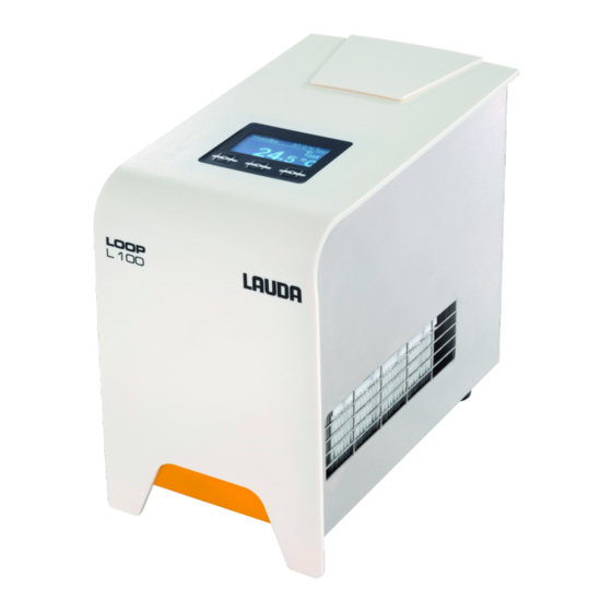
Setup and operating buttons Setup and operating buttons 3.1 Setup of the device Fig. 1: Front side LOOP Controller with temperature display and control buttons (soft buttons) Cover over the tank lid Ventilation openings 4 feet LOOP... - Page 12 Setup and operating buttons Fig. 2: Rear LOOPL 100 Device panel plug Box for 2 safety fuses Mains switch Type plate RS 232 interface (socket) Pump connection OUT inlet (to consumer) Pump connection IN outlet (back from consumer) LOOP...
- Page 13 Setup and operating buttons Fig. 3: Rear LOOP 250 Device panel plug Box for 2 safety fuses Mains switch Type plate RS 232 interface (socket) Pump connection OUT inlet (to consumer) Pump connection IN outlet (back from consumer) Fig. 4: Tank with filler nozzle and cover Fig.
-
Page 14: Mains Switch
Setup and operating buttons Fig. 6: Ventilation openings on the underside The device sucks up fresh air from below! 3.2 Mains switch The mains switch can be set to the following positions: Position [I] switches the device on. Position [O] switches the device off. -
Page 15: Operating Buttons
Setup and operating buttons 3.3 Operating buttons The three operating buttons can be used to control the functions of the device. Use the [Set] button to configure the set temperature. Use the [Menu] button to pull up the menu, in order to con- figure settings. -
Page 16: Commissioning
Commissioning Commissioning 4.1 Set up and connect the hoses WARNING! Danger of device falling or overturning Crushing, impacts Do not tilt the device. Position the device on an even, non-slip surface with a sufficient load carrying capacity. Do not position the device close to table edges. -
Page 17: Lauda Heat Transfer Liquid
Commissioning 4.2 LAUDA heat transfer liquid Take the following information into account: The heat transfer liquids each cover a recommended tem- perature range and must be suitable for the temperature range associated with their application. Never use contaminated or degenerated heat transfer liquids. -
Page 18: Filling With Heat Transfer Liquid And Draining
Take the following information into account: The device is designed exclusively for non-flammable heat transfer liquids. LAUDA is not liable for damages resulting from the use of unsuitable heat transfer liquids. Only connect pressure-sealed consumers to the device. ... - Page 19 Commissioning The tank is ventilated through the tank lid. Once the device is filled, do not tip it and never set it upside down! Empty the device before transporting it. Filling the tank Slide and remove the cover over the filler nozzle towards the back of the device.
-
Page 20: Establishing A Mains Connection
Commissioning 4.4 Establishing a mains connection NOTICE! Use of impermissible mains voltage or mains fre- quency Device damage Compare the type plate with the available mains voltage and mains frequency. Take the following information into account: Only use the supplied power cable for the power supply. ... -
Page 21: Operation
Operation Operation 5.1 General safety instructions CAUTION! Risk of heat transfer liquid escaping during opera- tion due to open consuming unit Scalding, cold burns Always use hydraulically sealed consuming units. CAUTION! Risk of heat transfer liquid escaping due to the use of unsuitable hoses Scalding, cold burns The temperature and media resistance of the hoses... -
Page 22: Loop Menu Structure
Operation 5.2 LOOP menu structure Fig. 10: Menu structure LOOP... -
Page 23: Set The Set Temperature T
Operation 5.3 Set the set temperature T The set temperature T is the temperature that the constant tem- perature equipment should reach and then maintain. is the outflow temperature of the device. In a well-controlled system, the outflow temperature is the same as the set temperature. -
Page 24: Set Temperature Limit Values Til And Tih
Operation 5.5 Set temperature limit values Til and Tih These menu items are used to set temperature limit values Til and Tih. The temperature limit values limit the entry range for the set temperature. A warning is issued if the temperature Tint is outside the temperature limit range. -
Page 25: Change The Calibration Of The Temperature Probe
Operation Press [OK] to confirm. Change the new value with the arrow buttons. Press [OK] to confirm. The setting is changed. 5.7 Change the calibration of the temperature probe A calibrated reference thermometer with the desired level of accuracy is necessary. Otherwise you should not change the calibration. -
Page 26: Restore Factory Setting
Operation Wait until the displayed bath temperature T matches the set temperature T Select the Menu Setup Calibration intern Pt1000 2-Punkt upper menu item. Enter the temperature value read off the reference thermom- eter into the device. Press [OK] to confirm the new value. -
Page 27: Viewing The Device Status
Operation 5.9 Viewing the device status In the “Device status” menu item, you can have the different cur- rent technical data of your device displayed. It isn’t possible to set or change values. You can have the following data displayed: ... -
Page 28: Control
Operation 5.10 Control 5.10.1 Control basics Definition A brief explanation of terms Actuating - Initial value of the controller to compensate for the signal difference between the actual value and target value (control deviation). PID con- - The PID controller operates with extreme speed troller and precision and consists of a P, I and D-compo- nent. - Page 29 Operation Influence of control parameters on the control action Fig. 11: Ideal setting If the Xp parameter selected is too large, the actual value will reach the proportional range early and the P-component will be less than 100 % of the actuating signal. It takes longer to reach the target value and as a result, the simultaneously integrated I-component has more time to establish its actuating signal component.
-
Page 30: Overview Of Control Parameters
Operation In the case shown here, the preset I-component is too large (parameter Tn too small, Tn must be increased). The I-component integrates the control deviation until it becomes 0. If integration proceeds too rapidly, the actuating signal, i.e. the output signal of the controller, is too large. -
Page 31: Editing Control Parameters
Operation 5.10.3 Editing control parameters The [Tv man/auto] menu item allows you to define whether the control parameters [Tv] and [Td] are adapted manually or config- ured automatically. If the automatic setting is enabled, both control parameters are marked with the letter "a" and a lock symbol and cannot be selected. -
Page 32: Protocol Rs 232
Operation Take the following information into account: With hardware handshake: When connecting a thermostat to the PC, use a 1:1 and not a null modem cable. The RS 232 interface can be connected directly to the PC using a 1:1 con- tacted cable. -
Page 33: Write Commands
Operation 5.11.3 Write commands Write commands are data specifications from the PC to the ther- mostat. Command Description Desired value transfer with maximum 3 places in front of the decimal OUT_SP_00_XXX.XX point and a maximum of 2 places after. OUT_SP_04_XXX Write [Hi] Outflow temperature limit upper value OUT_SP_05_XXX Write [Lo] Outflow temperature limit lower value... -
Page 34: Error Messages
Operation Command Description IN_SP_05 Query of outflow temperature limit Lo IN_PAR_00 Query of the control parameter Xp IN_PAR_01 Query of the control parameter Tn (181 = OFF) IN_PAR_02 Query of the control parameter Tv IN_PAR_03 Query of the control parameter Td IN_MODE_00 Keyboard master: 0 = free / 1 = blocked IN_MODE_02... - Page 35 Operation Error Description ERR_6 Impermissible value The upper temperature limit is lower than or equal to the lower tem- ERR_32 perature limit. LOOP...
-
Page 36: Maintenance
Maintenance Maintenance 6.1 General safety instructions DANGER! Contact with live or moving parts Electric shock, impacts, cutting, crushing The device must be disconnected from the mains power supply before any kind of maintenance is performed. Only skilled personnel are permitted to perform repairs. -
Page 37: Check The Heat Transfer Liquid
If you are unsure whether decontaminants or cleaning agents are compatible with parts of the device or the materials con- tained in those parts, please contact LAUDA Service Tem- perature control devices. LOOP... -
Page 38: Technical Data
Technical data Technical data The information has been conveyed in accordance with DIN 12876. Specification Unit Loop 100 Loop 250 Working temperature range °C 4 – 80 Temperature stability ±0.1 Ambient temperature range °C 5 – 40 Storage temperature °C 5 –... - Page 39 Technical data Specification Unit Loop 100 Loop 250 Protection level according to DIN EN 61140 Safety fuse 2 pieces SP 5x20 F 250V 6.3A H (EES 074) Device dimensions ‑ Width ‑ Depth ‑ Height Weight 11.9 Noise level (1m) dB(A) *Measured at 100 % setting [Fan Limit] Ä...
-
Page 40: General
The manufacturer reserves the right to make technical modifica- tions to the device. 8.3 Warranty conditions LAUDA grants a standard warranty of one year on all devices. 8.4 Contact LAUDA Contact LAUDA Service Constant temperature equipment in the following cases: For device errors ... -
Page 41: Eu Conformity
The device complies with the basic health and safety requirements outline in the Directives listed below. Machinery Directive 2006/42/EC EMC Directive 2014/30/EU LAUDA DR. R. WOBSER GMBH & CO. KG - Pfarrstrasse 41/43 - 97922 Lauda-Königshofen - Germany LOOP... -
Page 42: Index
Cleaning ....... 37 LAUDA heat transfer liquids ....17 Conformity (EU) . - Page 43 Index Service (LAUDA, Constant temperature equip- Til ....... . . 24, 26 ment) .
- Page 45 / Personne responsable Hiermit bestätigen wir, daß nachfolgend aufgeführtes LAUDA-Gerät (Daten vom Typenschild): We herewith confirm that the following LAUDA-equipment (see label): Par la présente nous confirmons que l’appareil LAUDA (voir plaque signalétique): Serien-Nr. Type / Type Serial no. / No. de série:...
- Page 48 LAUDA DR. R. WOBSER GMBH & CO. KG Pfarrstrasse 41/43 ◦ 97922 Lauda-Königshofen ◦ Germany Tel.: +49 (0)9343 503-0 ◦ Fax: +49 (0)9343 503-222 email: info@lauda.de ◦ Internet: www.lauda.de...
Need help?
Do you have a question about the L 100 and is the answer not in the manual?
Questions and answers