Table of Contents
Advertisement
Operating Instructions
Ecoline
Low-temperature thermostats
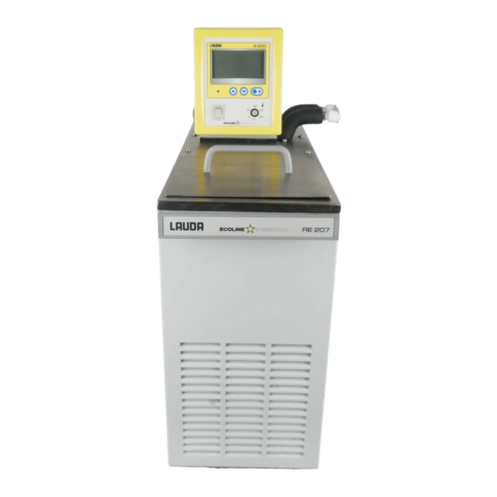
RE 204, RE 206, RE 207,
RE 210, RE 212, RE 220
LAUDA DR. R. WOBSER
GMBH & CO. KG
P.O. Box 1251
97912 Lauda-Königshofen
Germany
From Series A 20 (see item 8.3)
Phone: (+49) (0) 9343/ 503-0
from Software version 3.4
Fax: (+49) (0) 9343/ 503-222
02/03
e-mail info@lauda.de
YACE0060
Internet http://www.lauda.de
Advertisement
Table of Contents

Related Manuals for Lauda Ecoline RE 204


Summary of Contents for Lauda Ecoline RE 204
- Page 1 Operating Instructions Ecoline Low-temperature thermostats RE 204, RE 206, RE 207, RE 210, RE 212, RE 220 LAUDA DR. R. WOBSER GMBH & CO. KG P.O. Box 1251 97912 Lauda-Königshofen Germany From Series A 20 (see item 8.3) Phone: (+49) (0) 9343/ 503-0 from Software version 3.4...
- Page 3 Safety notes Before operating the equipment please read carefully all the instructions and safety notes. If you have any questions please phone us! Follow the instructions on setting up, operation etc. This is the only way to avoid incorrect operation of the equipment and to ensure full warranty protection. •...
-
Page 4: Table Of Contents
BRIEF OPERATING INSTRUCTIONS ..................1 CONTROL AND FUNCTIONAL ELEMENTS ................3 UNIT DESCRIPTION........................4 Unit types ........................... 4 Pumps..........................4 Temperature indication, control, and safety circuit ............4 Materials ..........................5 Refrigeration system ......................5 Serial Interfaces RS 232, RS 485 ..................6 3.6.1 RS 232 Interface ..........................6 3.6.2... - Page 5 6.4.4.3 Selection of the interface ......................28 6.4.4.4 Setting the Baud rate/ transfer rate (serial interface) ..............29 6.4.4.5 User calibration..........................30 Warning and safety functions ..................31 6.5.1 Overtemperature protection and testing ..................31 6.5.2 Low-level protection and testing....................33 6.5.3 Pump motor monitoring ......................34 6.5.4 Connection floating contact ”Combination fault”...
- Page 6 Explanation of signs Danger: This sign is used where there may be injury to personnel if a recommendation is not followed accurately or is disregarded. Note Here special attention is drawn to some aspect. May include reference to danger. Reference: Refers to other information in different Sections.
-
Page 7: Brief Operating Instructions
Brief operating instructions Brief operating instructions This brief instruction shall give you the possibility to operate the unit quickly. For safe operation of the unit it is absolutely necessary to read carefully all the instructions and safety notes! 1. Assemble unit and add items as appropriate ( Section 5). - Page 8 Brief operating instructions...
-
Page 9: Control And Functional Elements
Control and functional elements Control and functional elements Cooling LED green, Supply ON Menu functions Mains switch Setting of the overtemperature switch-off point Pump connections − return Pump connection: − outflow Bath bridge Bath cover 15.05.01 YACE0060... -
Page 10: Unit Description
Unit description Unit description Unit types The type designation of the Ecoline low-temperature thermostats consists of the letter R (identification as low-temperature unit), the control unit E 200 and the type of bath and refrigeration system Example: Control unit E 200 and bath RE 004 produces Thermostat Type RE 204. Type RE 220 is supplied without bath cover. -
Page 11: Materials
Unit description independent of the control function A low-level protection switches off the heating on both poles in order to prevent dry operation of the heater. The pump is switched off electronically. The overtemperature switch-off point is adjusted with a tool on a potentiometer and is always limited to 5 °C above the operating temperature range. -
Page 12: Serial Interfaces Rs 232, Rs 485
Unit description Serial Interfaces RS 232, RS 485 3.6.1 RS 232 Interface Computer Thermostat Data 9-pin sub-D 25-pin sub-D 9-pin sub-D socket Data socket socket R x D T x D T x D R x D Signal Signal Ground Ground with Hardware Handshake: When connecting the thermostat to the computer please use a 1:1 cable and not a zero-modem-cable! - Page 13 Unit description Protocol: − The interface operates with 1 stop bit, no parity bit and 8 data bits. − Transfer rate either 2400, 4800, 9600 (factory setting) or 19200 baud as selected. − The RS232 interface can be operated with or without hardware handshake (RTS/CTS). −...
-
Page 14: Rs 485 Interface
Unit description 3.6.2 RS 485 Interface Connecting cable: Thermostat 9-pin sub-D-socket Data Data A SG (Signal Ground) optional Data B − Use screened connecting cables. − Connect the screen to the plug case. − The lines are electrically isolated from the remaining electronics. −... - Page 15 Unit description − The response of the thermostat is always terminated with CR. CR = carriage return (hex: 0D) Example: Transfer of setpoint 30.5°C to the thermostat with address 15. Computer Thermostat " „A015_OUT_SP_00_30.5“CR „A015_OK“CR 15.05.01 YACE0060...
-
Page 16: Write Commands (Data Commands To The Thermostat)
Unit description 3.6.3 Write commands (data commands to the thermostat) Command Explanation OUT_SP_00_XXX.XX Setpoint transfer with up to 3 places before the decimal point and up to 2 places behind OUT_SP_01_XXX Pump output step 1, 2, 3, 4, or 5; 0 = Stop (Standby) OUT_SP_02_XXX Refrigerator 0 = OFF / 1 = ON 100% / 2 = 50% (reduced capacity RE 207, 210, 212, 220) / 3 = automatic operation... -
Page 17: Read Commands (Data Requested From Thermostat)
Unit description 3.6.4 Read commands (data requested from thermostat) Command Explanation IN_PV_00 Read bath temperature (outflow temperature) IN_SP_00 Read temperature setpoint IN_SP_01 Read pump output step IN_SP_02 Read operating mode of refrigerator 0 = OFF / 1 = ON 100% / 2 = ON 50% (reduced capacity RE 207, 210, 212, 220) / 3 = automatic operation IN_SP_03 Read current overtemperature switch-off point... -
Page 18: Error Messages
WK/WKL units can be programmed with the aid of the National Instruments program ® development tool LABVIEW (http://sine.ni.com/apps/we/nioc.vp?cid=1381&lang=US). In order to make program operation possible on the RS 232/ RS 485 interface, LAUDA provides ® drivers specially designed for LABVIEW which can be downloaded free of charge under... -
Page 19: Unpacking
Unpacking Unpacking After the unit and accessories have been unpacked they have to be examined for possible transport damage. If there is any damage visible on the unit, the forwarding agent or the post office has to be notified so that the shipment can be examined. Standard accessories: Bath cover on all low-temperature thermostats except RE 220... -
Page 20: Preparations
Preparations Preparations Assembly and setting up − Place the unit on a flat surface − After transport and before starting up, store it standing in upright position for two hours if possible. − Do not cover the ventilation openings at the back of the unit and ist lower part. -
Page 21: Filling And Emptying
Preparations − When operating as bath thermostat without external consumer the pump connection outflow has to be closed (use closing plugs) or linked to the return. − At bath temperature above 70°C the label supplied must be affixed on the bath in a clearly visible position! −... - Page 22 Preparations Emptying − Switch off the thermostat, pull out the mains plug! b) Drain the bath liquid through the drain cock ! using tubing. − The units are designed for operation with non-flammable and flammable liquids to EN 61010-2-010! Flammable liquids can be operated up to no more than 25°C below the firepoint ( Section 5.3.).
-
Page 23: Bath Liquids And Hose Connections
Preparations Bath liquids and hose connections Bath liquids LAUDA Working Chemical Visco- Viscosity Fire- Ref.No. Designation tem- Designation sity (kin) at point Quantity perature (kin) Temperature range Former from °C mm²/s mm²/s 10 l 20 l designation to °C at 20°C... - Page 24 Preparations Hose connections a) Elastomer tubing Tubing type Int. dia. Temperature Application Ref. No. Ø mm range °C EPDM-tubing, 10 to 120 for all bath RKJ 111 uninsulated liquids except for Ultra 350 and mineral oils EPDM-tubing, 10 to 120 for all bath RKJ 112 uninsulated...
-
Page 25: Connection Of External Circuits
Preparations Connection of external circuits Operation as circulation thermostat − Connect 11-12 mm int. dia. tubing ( Section 5.3.) to the pump connector. − Pump connection outflow always in front, return connection always at the back. − If the cross-section of the tubing is too small ! temperature drop between bath and external system due to low flow rate. -
Page 26: Starting Up
Starting up Starting up Connection to the supply Compare the supply voltage against the data on the rating label. Model according to EMC directive EN 61326-1 class B.* − Connect the unit only to a grounded mains power socket (PE). −... -
Page 27: Setpoint Selection (Level 0)
Starting up $ $ $ $ − A double signal tone sounds. − The display for LEVEL (low-level) appears. − The fault triangle is flashing − Press the key. If necessary repeat several times. − Also press the key if the unit had switched off under a fault condition. -
Page 28: Menu Functions
Starting up Menu functions − Switching from setpoint selection (level 0) to level 1 using the key − Within one level it is possible to scroll using the keys. − In principle, after each setting has been made it is entered automatically after approx. -
Page 29: Pump Output
Starting up 6.4.2 Pump output − For setting the pump output from level 0 press the key and 1x combination shown on the left, or − move forward from COOL function with this key. − The display shows the current bath temperature, PUMP and the current output step. -
Page 30: Setting The Setpoint Resolution
Starting up 6.4.3 Setting the setpoint resolution − To set the setpoint resolution from level 0 press the key and 2x combination on the left or − move forward with the key from the PUMP-function. − The current bath temperature, RES and the current setpoint resolution are indicated. -
Page 31: Parameters
Starting up 6.4.4 Parameters − Directly from level 0 (setpoint selection) press the key and 3x combination on the left, or − forward with the key from function setpoint resolution. − Here it is possible to switch over to level 2. Press the key on the left, continue with Section 6.4.4.1. -
Page 32: Setting The Proportional Band Of The Pid-Controller
Starting up 6.4.4.1 Setting the proportional band of the PID-controller − Directly from level 0 (setpoint selection), press the key and 3x combination on the left, until the PARA function is reached, then − switch to level 2 from PARA (see above) with key on the left. -
Page 33: Setting The Reset Time Of The Pid-Controller
Starting up 6.4.4.2 Setting the reset time of the PID-controller − Directly from level 0 (setpoint selection), press the key and 3x combination on the left, until the PARA function is reached, then − switch to level 2 and move forward with the keys on the left. and 1x −... -
Page 34: Selection Of The Interface
Starting up 6.4.4.3 Selection of the interface − Directly from level 0 (setpoint selection), press the key and 3x combination on the left, until the PARA function is reached, then − switch to level 2 and move forward with key on the left and 2x −... -
Page 35: Setting The Baud Rate/ Transfer Rate (Serial Interface)
Starting up 6.4.4.4 Setting the Baud rate/ transfer rate (serial interface) − Directly from level 0 (setpoint selection), press the key and 3x combination on the left, until the PARA function is reached, then − switch to level 2 and move forward with key on the left. and 3x −... -
Page 36: User Calibration
Starting up 6.4.4.5 User calibration − Remove the external consumers and switch the setting knob of the pump to right side. ( Section 5.4). − A reference thermometer with necessary accuracy is required. Otherwise the factory calibration should not be altered. The reference thermometer has to be inserted far enough and long enough into the bath. -
Page 37: Warning And Safety Functions
Starting up 6. Switch back to level 0 or 7. with key back to "Setting the transfer rate Example a) Insert a suitable thermometer into the bath (long enough and far enough). b) Remove the external consumers and turn the setting knob of the pump outflows to the right side. - Page 38 Starting up − The position of the potentiometer is decisive for the setting. The display is just a help for the setting. − Setting is possible only up to a upper limit of the operating temperature range + 5 °C. $ $ $ $ −...
-
Page 39: Low-Level Protection And Testing
! − If there is any irregularity when testing the safety devices, switch off the unit immediately and pull out the mains plug ! − Have the unit checked by the LAUDA service or the local service organisation! 15.05.01 YACE0060... -
Page 40: Pump Motor Monitoring
Starting up 6.5.3 Pump motor monitoring − In case of pump motor overload or a blockage the heating and the pump are switched off. ! ! ! ! − Double signal tone sounds. − The display shows PUMP and the fault triangle is flashing −... -
Page 41: Other Error Messages
Starting up 6.5.5 Other error messages − E 0 etc. is flashing in the bottom line ! various temperature probe faults. ! pump fault, proceed as in Section 6.5.3. − If the fault report is repeated ! pull out the mains plug and try whether the motor can be rotated by the fan blade inserting a screwdriver into the ventilation opening at the back of the unit. -
Page 42: Safety Notes
Safety notes Safety notes General safety notes A laboratory thermostat is intended for heating and pumping liquids according to the needs of the user. This leads to hazards by high temperatures, fire, and the general hazards by the use of electrical energy. The user is largely protected through the application of the appropriate standard specifications.. - Page 43 Safety notes • Depending on the bath liquid used and the mode of operation it is possible for toxic vapours to be produced. Ensure appropriate ventilation! • When changing the bath liquid from water to oil, for temperatures above 100 °C, carefully remove all traces of water, also from tubing and from the external consumer, otherwise ! danger of burns through delayed boiling! •...
-
Page 44: Maintenance
− Before any maintenance and repair work pull out the mains plug! − Repairs on the control unit must only be carried out by properly qualified personnel! LAUDA thermostats are largely maintenance-free. If the thermostating liquid becomes dirty it has to be replaced ( Section 5.2.). -
Page 45: Maintenance Of The Refrigeration Unit
If the equipment does have to be returned to the factory, it may only be necessary to dismantle the thermostat unit and return it. − If the equipment has to be returned to the factory, please ensure that it is carefully and properly packed. LAUDA accepts no responsibility for damage due to unsatisfactory packing. Ordering spares When ordering spares please quote instrument type and serial number from the rating label. -
Page 46: Technical Data (To Din 58966)
Technical data Technical data (to DIN 58966) Low-temperature thermostats RE 204 RE 206 RE 207 RE 210 RE 212 RE 220 Operating temperature range °C -10 to 200 -20 to 200 -35 to 200 -40 to 200 -30 to 200 -30 to 200 Ambient temperature range °C... - Page 47 Technical data Standard settings of control parameters and pump Section 6.4.4.1. and 6.4.4.2. Unit Type Xp (°C) Tn (s) Pump outflow step RE 204 RE 206 RE 207 RE 210 RE 212 RE 220 Pump characteristics measured with water 0,45 0,35 step 5 step 4...
- Page 48 Technical data Cooling curve measured with ethanol RE 210 min. Bath liquid: Time from graph water/glycol 1:1 x 1,7 (to -25°C) as bath liquid We reserve the right to make technical alterations!
-
Page 49: Accessories
Accessories Accessories Accessories suitable for Ref. No. Bath cover two parts RE 220 LCZ 0633 Gable cover RE 220 LCZ 011 Rising platform 8 steps RE 206, RE 207 LCZ 0646 Rising platform 8 steps RE 210, RE 212 LCZ 0647 Rising platform 8 steps RE 220 LCZ 0635... -
Page 50: Circuit Diagram
Circuit diagram Circuit diagram... - Page 51 Circuit diagram 18.03.03 YACE0060...
- Page 52 Circuit diagram 230V; 50Hz 230V; 50/60Hz [230V; 60Hz] at Serialno.: A 20 RE 2xx Printed circuit board „Mains“ UL 487-1 Printed circuit board „Display“ UL 488-1B Printed circuit board serial interface RS 232/RS 485 UL 490 Printed circuit board Mains LED-Backlight --------- Printed circuit board Display LED-Backlight ---------...
- Page 53 Circuit diagram 115V; 60Hz [100V; 50/60Hz] 208-230V;60Hz at Serialno.: A 20 RE 2xx Printed circuit board „Mains“ UL 499 Printed circuit board „Display“ UL 488-1B Printed circuit board serial interface RS 232/RS 485 UL 490 Printed circuit board Mains LED-Backlight --------- Printed circuit board Display LED-Backlight ---------...
-
Page 54: Pipe Plan
Pipe plan Pipe plan... - Page 55 Pipe plan 18.03.03 YACE0060...
- Page 56 Pipe plan 230V; 50Hz 230V; 50/60Hz [230V; 60Hz] at Serialno.: A 20 RE 2xx RE 004 Pressure switch CC80 24/18bar ES 045 Compressor GD 36 AC EMV 050 4715MS-10T-B50-B00 EML 052 Drier EO 003 Capillary HKA 114 Evaporator ---------- Bath ---------- RE 006 Pressure switch...
- Page 57 Pipe plan 115V; 60Hz [100V; 50/60Hz] 208-230V;60Hz at Serialno.: A 20 RE 2xx RE 004 Pressure switch CC80 24/18bar ES 045 Compressor GD 36 AC EMV 049 4715MS-10T-B50-B00 EML 051 Drier EO 003 Capillary HKA 114 Evaporator ---------- Bath ---------- RE 006 Pressure switch CC80 24/18bar...
- Page 59 / Personne responsable Hiermit bestätigen wir, daß nachfolgend aufgeführtes LAUDA-Gerät (Daten vom Typenschild): We herewith confirm that the following LAUDA-equipment (see label): Par la présente nous confirmons que l’appareil LAUDA (voir plaque signalétique): Serien-Nr. Type / Type Serial no. / No. de série:...
Need help?
Do you have a question about the Ecoline RE 204 and is the answer not in the manual?
Questions and answers