Table of Contents
Advertisement
Operating Instructions
Ecoline
Low-temperature thermostats
RE 204, RE 206, RE 207, RE 212, RE 220
RE 306, RE 307, RE 312, RE 320
LAUDA DR. R. WOBSER
GMBH & CO. KG
P.O. Box 1251
97912 Lauda-Königshofen
Germany
From Series X01
Phone: (+49) (0) 9343/ 503-0
Software version 3.1
Fax: (+49) (0) 9343/ 503-222
3/99
e-mail info@lauda.de
YACE0060
Internet http://www.lauda.de
Advertisement
Table of Contents

Related Manuals for Lauda Ecoline RE 204


Summary of Contents for Lauda Ecoline RE 204
-
Page 1: Operating Instructions
Operating Instructions Ecoline Low-temperature thermostats RE 204, RE 206, RE 207, RE 212, RE 220 RE 306, RE 307, RE 312, RE 320 LAUDA DR. R. WOBSER GMBH & CO. KG P.O. Box 1251 97912 Lauda-Königshofen Germany From Series X01 Phone: (+49) (0) 9343/ 503-0 Software version 3.1... -
Page 3: Safety Notes
Safety notes Before operating the equipment please read carefully all the instructions and safety notes. If you have any questions please phone us! Follow the instructions on setting up, operation etc. This is the only way to avoid incorrect operation of the equipment and to ensure full warranty protection. •... -
Page 4: Table Of Contents
1 BRIEF OPERATING INSTRUCTIONS...................1 2 CONTROL AND FUNCTIONAL ELEMENTS.................3 3 UNIT DESCRIPTION ........................4 3.1 Unit types ..........................4 3.2 Pumps.............................4 3.3 Temperature indication, control, and safety circuit ............4 3.4 Programmer (Types RE 3xx only) ..................5 3.5 Materials ..........................5 3.6 Refrigeration system ......................5 3.7 Serial Interfaces RS 232, RS 485...................6 3.7.1 Specification and interface test......................6 3.7.2 General information..........................7... - Page 5 6.4.4.2 Indicating/ altering of programme segments................25 6.4.4.3 Number of programme running....................27 6.4.4.4 Starting of the programmer......................28 6.4.4.5 Inserting/ deleting of programme segments ................29 6.4.4.6 Holding/continuing the programme ....................31 6.4.4.7 Terminating the programme ......................32 6.4.5 Parameters ............................33 6.4.5.1 Setting the proportional band of the PID-controller..............34 6.4.5.2 Setting the reset time of the PID-controller ..................35 6.4.5.3 Selection of the interface ......................35 6.4.5.4 Setting the Baud rate/ transfer rate (serial interface) ..............36...
- Page 6 Explanation of signs Danger: This sign is used where there may be injury to personnel if a recommendation is not followed accurately or is disregarded. Note Here special attention is drawn to some aspect. May include reference to danger. Reference: Refers to other information in different Sections.
-
Page 7: Brief Operating Instructions
Brief operating instructions Brief operating instructions This brief instruction shall give you the possibility to operate the unit quickly. For safe operation of the unit it is absolutely necessary to read carefully all the instructions and safety notes! 1. Assemble unit and add items as appropriate ( Section 5). - Page 8 Brief operating instructions...
-
Page 9: Control And Functional Elements
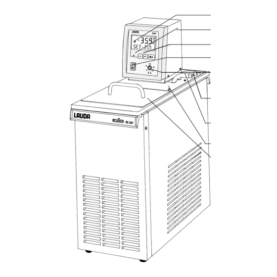
Control and functional elements Control and functional elements Cooling LED green, Supply ON Menu functions Mains switch Setting of the overtemperature switch-off point Pump connections − return Pump connection: − outflow Bath bridge Bath cover 10.08.99 YACE0060... -
Page 10: Unit Description
Unit description Unit description Unit types The type designation of the Ecoline low-temperature thermostats consists of the letter R (identification as low-temperature unit), the control unit E 200 or E 300, and the type of bath and refrigeration system Example: Control unit E 200 and bath RE 004 produces Thermostat Type RE 204. Type RE 220 is supplied without bath cover. -
Page 11: Programmer (Types Re 3Xx Only)
Unit description A Pt 100 temperature probe is used for measuring the actual temperature and for control. A second Pt 100 serves as temperature probe for the safety circuit (overtemperature protection) which is independent of the control function A low-level protection switches off the heating on both poles in order to prevent dry operation of the heater. -
Page 12: Serial Interfaces Rs 232, Rs 485
Unit description Serial Interfaces RS 232, RS 485 3.7.1 Specification and interface test Computer Thermostat Data 9-pin sub-D 25-pin sub-D 9-pin sub-D socket Data socket socket R x D T x D T x D R x D Signal Signal Ground Ground with Hardware Handshake: When connecting the thermostat to the computer please use a 1:1 cable and not a zero-modem-cable! -
Page 13: General Information
Unit description The RS 232 Interface can easily be tested with the PC connected, using the MS-Windows operating system. On Windows 3.11 with the programme "Terminal" and on Windows 95 with the programme "Hyper Terminal Terminal”. The RS 485 bus absolutely needs a bus-termination in form of a terminating network, which ensures a defined unattended time in the high resistance phases. -
Page 14: Output Commands
Unit description 3.7.3 Output commands Command Explanation OUT_SP_00_XXX.XX Setpoint transfer with up to 3 places before the decimal point and up to 2 places behind OUT_SP_01_XXX.XX Pump output step 1, 2, 3, 4 or 5, 0 = STOP OUT_SP_02_XXX.XX Operating mode of the refrigeration system “0“ = OFF, "1"... -
Page 15: Data Request From The Thermostat
Unit description Permitted data formats -XXX.XX -XXX.X -XXX. -XXX XXX.XX XXX.X XXX. -XX.XX -XX.X -XX. XX.XX XX.X -X.XX -X.X X.XX -.XX 3.7.4 Data request from the thermostat The response from the thermostat is always in the fixed format "XXX.XX" for negative values "-XXX.XX"... -
Page 16: Error Messages
Unit description IN_ERR_00 fault diagnosis microcontroller 1 IN_ERR_01 fault diagnosis microcontroller 2 IN_MODE_00 0 = RS 232 + keyboard/ 1 = only RS 232 interface (A015_IN_MODE_00 (0 = RS 485 + keyboard/1 = only RS 485 interface) -->RS485) Request to indicate the programme segments RMP_IN_00_XX (answer e.g 030.00_010.00 = 30.00 °C, 10 min) (1...20) -
Page 17: Unpacking
Unpacking Unpacking After the unit and accessories have been unpacked they have to be examined for possible transport damage. If there is any damage visible on the unit, the forwarding agent or the post office has to be notified so that the shipment can be examined. Standard accessories: Bath cover on all low-temperature thermostats except RE 220... -
Page 18: Preparations
Preparations Preparations Assembly and setting up − Place the unit on a flat surface − After transport and before starting up, store it standing in upright position for two hours if possible − Do not cover the ventilation openings at the back of the unit and its lower part. -
Page 19: Filling And Emptying
Preparations − The unit can be operated safely up to an ambient temperature of 40°C − Depending on the loading of the refrigeration system it may switch off temporarily especially at ambient temperatures above 35°C. Elevated ambient temperatures also result in reduced cooling capacity. −... - Page 20 Preparations Emptying − Switch off the thermostat, pull out the mains plug! b) Drain the bath liquid through the drain cock ! using tubing. − The units are designed for operation with non-flammable and flammable liquids to EN 61010-2-010! Flammable liquids can be operated up to no more than 25°C below the firepoint ( Section 5.3.).
-
Page 21: Bath Liquids And Hose Connections
Preparations Bath liquids and hose connections Bath liquids LAUDA Working Chemical Visco- Viscosity Fire- Ref.No. Designation tem- Designation sity (kin) at point Quantity perature (kin) Temperature range Former from °C at 20°C mm²/s mm²/s 10 l 20 l designation to °C... - Page 22 Preparations DIN Safety data sheets are available on request! Hose connections a) Elastomer tubing Tubing type Int. dia. Temperature Application Ref. No. Ø mm range °C Perbunan tubing, 0 to 120 for all bath RKJ 011 uninsulated liquids Perbunan tubing, -0 to 120 for all bath RKJ 012...
-
Page 23: Connection Of External Circuits
Preparations Connection of external circuits Operation as circulation thermostat − Connect 11-12 mm int. dia. tubing (for Types RE 3xx use metal hoses) ( Section 5.3.) to the pump connector − Pump connection outflow always in front, return connection always at the back. −... - Page 24 Preparations − Using the setting knob at the pump outflows, divide up the pump flow in accordance to the thermostating task.( Section 5.1) − Position ! maximum flow in the external circuit (setting knob turned anticlockwise). − Position ! flow passes through pump outflow and outlet for bath circulation (setting knob in medium position).
-
Page 25: Starting Up
Starting up Starting up Connection to the supply Compare the supply voltage against the data on the rating label. − Connect the unit only to a grounded mains power socket (PE). − No warranty when the thermostat is connected to a wrong supply! −... -
Page 26: Setpoint Selection (Level 0)
Starting up " " " " − A double signal tone sounds. − The display for LEVEL (low-level) appears. − The fault triangle is flashing − Press the key. If necessary repeat several times. − Also press the key if the unit had switched off under a fault condition. -
Page 27: Menu Functions
Starting up Menu functions − Switching from setpoint selection (level 0) to level 1 using the key − Within one level it is possible to scroll using the keys. − In principle, after each setting has been made it is entered automatically after approx. -
Page 28: Pump Output
Starting up − The refrigeration system can normally work with automatic operation = A. The refrigeration system switches on or off depending on the temperature and operation status. − In special cases the cooling machine can be switched off ! ”0” or adjusted at permanent running ! ”I”. -
Page 29: Setting The Setpoint Resolution
Starting up 6.4.3 Setting the setpoint resolution − To set the setpoint resolution from level 0 press the key and 2x combination on the left − move forward with the key from the PUMP-function. − The current bath temperature, RES and the current setpoint resolution are indicated. -
Page 30: Programmer (Types Re 3Xx Only)
Starting up 6.4.4 Programmer (Types RE 3xx only) − To view or to set the programmer, starting from level 0 and 3x (setpoint input) press the key combination on the left, or − from RES function scroll with this key. −... -
Page 31: Indicating/ Altering Of Programme Segments
Starting up 6.4.4.2 Indicating/ altering of programme segments − When PGM appears on the display (therefore proceed as described in 6.4.4.) press the key on the left. − The display shows RUN. Here the programmer can be started ( Section 6.4.4.4.) −... - Page 32 Starting up − The variable currently activated flashes quickly (here the segment number). − To alter the required variable start with this key − If e.g. the segment number is flashing, all segments can be indicated in sequence by pressing one of the two keys, −...
-
Page 33: Number Of Programme Running
Starting up − While the programmer is in operation segments can be altered (including the current segment) and new segments can be inserted. All segments can also be deleted at each time (except the current segment) ( Section 6.4.4.5.) BUT: If the new segment time is shorter than the segment time which has already elapsed, the next segment is activated. -
Page 34: Starting Of The Programmer
Starting up − with key back to "setpoint selection". (level 0). 6.4.4.4 Starting of the programmer − From level 0 proceed as described under 6.4.4. When PGM appears on the display, press the key on the left. − The display shows RUN, or −... -
Page 35: Inserting/ Deleting Of Programme Segments
Starting up 6.4.4.5 Inserting/ deleting of programme segments 1. From level 0 proceed as described under 6.4.4. When PGM appears on the display, press the key on the left. 2. The display shows RUN (or STOP if the programmer had been started). - Page 36 Starting up − When a new segment is inserted, all subsequent segments are shifted on by one position.( example Section 6.4.4.1). − When 20 segments are inserted, the last one will disappear when a new segment will be input. − New segments can also be inserted while the programmer is activated. −...
-
Page 37: Holding/Continuing The Programme
Starting up − − − − To input a segment time longer than 255 min it has to be split between several consecutive segments. 6.4.4.6 Holding/continuing the programme When the programmer is activated, the programme can at any time be held and be continued again. For this 1. -
Page 38: Terminating The Programme
Starting up 6.4.4.7 Terminating the programme − From level 0 proceed as described under 6.4.4. When the display shows PGM, press the key. − The display shows STOP. The current segment is indicated after STOP. Press the key, the programme is terminated immediately −... -
Page 39: Parameters
Starting up 6.4.5 Parameters − Directly from level 0 (setpoint selection) press the key and 4x combination on the left (on RE 3xx) − on RE 2xx , or and 3x − forward with the key from PGM function. − Here it is possible to switch over to level 2. Press the key on the left, continue with Section 6.4.5.1. -
Page 40: Setting The Proportional Band Of The Pid-Controller
Starting up 6.4.5.1 Setting the proportional band of the PID-controller − Directly from level 0 (setpoint selection), press the key and 4x and 3x combination on the left (top one on RE 3xx, bottom one RE 2xx), until the PARA function is reached, then −... -
Page 41: Setting The Reset Time Of The Pid-Controller
Starting up 6.4.5.2 Setting the reset time of the PID-controller − Directly from level 0 (setpoint selection), press the key and 4x and 3x combination on the left (top one on RE 3xx, bottom one RE 2xx), until the PARA function is reached, then −... -
Page 42: Setting The Baud Rate/ Transfer Rate (Serial Interface)
Starting up RE 2xx), until the PARA function is reached, then − switch to level 2 and move forward with key on the left and 2x − The display shows the current bath temperature and the currently set interface. To alter the setting press the key. −... - Page 43 Starting up − switch to level 2 and move forward with key on the left. and 3x − The display shows the current bath temperature, KBD and the current setting. To alter the setting press the key. − Display flashes (approx. 4 s). −...
-
Page 44: User Calibration
Starting up 6.4.5.5 User calibration − Remove the external consumers and switch the setting knob of the pump to right side. ( Section 5.4). − A reference thermometer with necessary accuracy is required. Otherwise the factory calibration should not be altered. The reference thermometer has to be inserted far enough and long enough into the bath. -
Page 45: Warning And Safety Functions
Starting up 6. Switch back to level 0 or 7. with key back to "Setting the transfer rate Example a) Insert a suitable thermometer into the bath (long enough and far enough). b) Remove the external consumers and turn the setting knob of the pump outflows to the right side. - Page 46 Starting up − When the switch-off point is being adjusted by more than 2°C ! display shows MAX and actual overtemperature switch-off point with 1°C resolution for approx. 4 s. − The position of the potentiometer is decisive for the setting. The display is just a help for the setting.
-
Page 47: Low-Level Protection And Testing
! − If there is any irregularity when testing the safety devices, switch off the unit immediately and pull out the mains plug ! − Have the unit checked by the LAUDA service or the local service organisation! 10.08.99 YACE0060... -
Page 48: Pump Motor Monitoring
Starting up 6.5.3 Pump motor monitoring − In case of pump motor overload or a blockage the heating and the pump are switched off. " " " " − Double signal tone sounds. − The display shows PUMP and the fault triangle is flashing −... -
Page 49: Other Error Messages
Starting up 6.5.5 Other error messages − E 0 etc. is flashing in the bottom line ! various temperature probe faults. ! pump fault, proceed as in Section 6.5.3. − If the fault report is repeated ! pull out the mains plug and try whether the motor can be rotated by the fan blade inserting a screwdriver into the ventilation opening at the back of the unit. -
Page 50: Safety Notes
Safety notes Safety notes General safety notes A laboratory thermostat is intended for heating and pumping liquids according to the needs of the user. This leads to hazards by high temperatures, fire, and the general hazards by the use of electrical energy. The user is largely protected through the application of the appropriate standard specifications.. - Page 51 Safety notes • Depending on the bath liquid used and the mode of operation it is possible for toxic vapours to be produced. Ensure appropriate ventilation! • When changing the bath liquid from water to oil, for temperatures above 100 °C, carefully remove all traces of water, also from tubing and from the external consumer, otherwise ! danger of burns through delayed boiling! •...
-
Page 52: Maintenance
− Before any maintenance and repair work pull out the mains plug! − Repairs on the control unit must only be carried out by properly qualified personnel! LAUDA thermostats are largely maintenance-free. If the thermostating liquid becomes dirty it has to be replaced ( Section 5.2.). -
Page 53: Maintenance Of The Refrigeration Unit
If the equipment does have to be returned to the factory, it may only be necessary to dismantle the thermostat unit and return it. − If the equipment has to be returned to the factory, please ensure that it is carefully and properly packed. LAUDA accepts no responsibility for damage due to unsatisfactory packing. Ordering spares When ordering spares please quote instrument type and serial number from the rating label. -
Page 54: Technical Data (To Din 58966)
Technical data Technical data (to DIN 58966) Low-temperature thermostats RE 204 RE 206 RE 207 RE 212 RE 220 Operating temperature range °C -10 to 200 -20 to 200 -35 to 200 -30 to 200 -30 to 200 Ambient temperature range °C 5...40 (#Section 5.1) -
Page 55: Technical Data
Technical data RE 306 RE 307 RE 312 RE 320 Operating temperature range °C -20...200 -35...200 -30...200 -30...200 5...40 ( # Section 5.1.) Ambient temperature range °C Setting resolution °C 0.01 Indication resolution °C 0.05 Indication accuracy ±0.2 °C additive re-calibration Temperature control ±°C 0.01... - Page 56 Technical data Standard settings of control parameters and pump Section 6.4.5.1. and 6.4.5.2. and 6.4.2. Unit Type Xp (°C) Tn (s) Pump outflow step RE 104, RE 204 RE 106, RE 206, RE 306 RE 107, RE 207, RE 307 RE 112, RE 212, RE 312 RE 120, RE 220, RE 320 Pump characteristics...
- Page 57 Technical data Cooling curve measured with ethanol Bath liquid: Time from graph water/glycol 1:1 x 1,7 (to -25°C) as bath liquid We reserve the right to make technical alterations! 10.08.99 YACE0060...
-
Page 58: Accessories
Accessories Accessories Accessories suitable for Ref. No. Bath cover two parts RE 220 LCZ 0633 Gable cover RE 220, RE 320 LCZ 011 Rising platform 8 steps RE 206, RE 306, RE 207, LCZ 0646 RE 307 Rising platform 8 steps RE 212, RE 312 LCZ 0647 Rising platform 8 steps... -
Page 59: Circuit Diagram
Circuit diagram Circuit diagram 10.08.99 YACE0060... - Page 60 Circuit diagram...
-
Page 61: Circuit Diagram
Circuit diagram 230V; 50Hz 230V; 50/60Hz [230V; 60Hz] at Serialno.: X01 RE 1xx RE 2xx RE 3xx Printed circuit board „Mains“ UL 487-1 UL 487-1 UL 487-1 Printed circuit board „Display“ UL 488-1A UL 488-1B UL 488-1C Printed circuit board serial interface RS 232/RS 485 ---------- UL 490 UL 490... - Page 62 Circuit diagram 115V; 60Hz [100V; 50/60Hz] at Serialno.: X01 RE 1xx RE 2xx RE 3xx Printed circuit board „Mains“ UL 499 UL 499 UL 499 Printed circuit board „Display“ UL 488-1A UL 488-1B UL 488-1C Printed circuit board serial interface RS 232/RS 485 ---------- UL 490 UL 490...
-
Page 63: Pipe Plan
Pipe plan Pipe plan 16.08.99 YACE0060... - Page 64 Pipe plan...
-
Page 65: Pipe Plan
Pipe plan 16.08.99 YACE0060... - Page 66 Pipe plan 230V; 50Hz 230V; 50/60Hz [230V; 60Hz] at Serialno.: X01 RE 1xx RE 2xx RE 3xx RE 004 Pressure switch CC20 24/17 bar ES 045 ES 045 ---------- M 2+M 3+J 5 Cooling unit PL 50 FX NO EMK 173 EMK 173 ---------- Drier...
- Page 67 Pipe plan 1150V; 60Hz [100V; 50/60Hz] at Serialno.: X01 RE 1xx RE 2xx RE 3xx RE 004 Pressure switch CC20 24/17 bar ES 045 ES 045 ---------- M 2+M 3+J 5 Cooling unit PL 50 FX NO EMK 176 EMK 176 ---------- Drier EO 003...
- Page 69 / Personne responsable Hiermit bestätigen wir, daß nachfolgend aufgeführtes LAUDA-Gerät (Daten vom Typenschild): We herewith confirm that the following LAUDA-equipment (see label): Par la présente nous confirmons que l’appareil LAUDA (voir plaque signalétique): Serien-Nr. Type / Type Serial no. / No. de série:...
Need help?
Do you have a question about the Ecoline RE 204 and is the answer not in the manual?
Questions and answers