Table of Contents
Advertisement
Quick Links
Advertisement
Table of Contents

Related Manuals for Advantech EKI-1321


Summary of Contents for Advantech EKI-1321
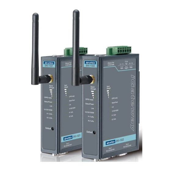
- Page 1 User Manual EKI-1321/1322 1/2-port RS-232/422/485 to GPRS IP Gateway...
- Page 2 No part of this manual may be reproduced, copied, translated or transmitted in any form or by any means without the prior written permission of Advantech Co., Ltd. Information provided in this manual is intended to be accurate and reliable. How- ever, Advantech Co., Ltd.
-
Page 3: Declaration Of Conformity
Consult the dealer or an experienced radio/TV technician for help. Technical Support and Assistance Visit the Advantech web site at www.advantech.com/support where you can find the latest information about the product. Contact your distributor, sales representative, or Advantech's customer service center for technical support if you need additional assistance. - Page 4 The sound pressure level at the operator's position according to IEC 704-1:1982 is no more than 70 dB (A). DISCLAIMER: This set of instructions is given according to IEC 704-1. Advantech disclaims all responsibility for the accuracy of any statements contained herein.
-
Page 5: Table Of Contents
Table 2.1: EKI-1321/1322 LED Indicators ......... 12 2.2.2 Dimensions (Units: mm).............. 13 Figure 2.7 Front View of EKI-1321/1322 ........13 Figure 2.8 Side View of EKI-1321/1322........14 Figure 2.9 Back View of EKI-1321/1322........14 Figure 2.10Top View of EKI-1321/1322........14 Figure 2.11Bottom View EKI-1321/1322 ........ - Page 6 Connected IP information ............60 5.10 Alert......................61 5.10.1 Setting..................61 5.10.2 Event................... 62 5.11 LogFile ....................62 5.12 Change Password................... 62 5.13 Reboot ....................63 Appendix A Troubleshooting........ 65 Successful GPRS Connection ..............66 Failed GPRS Connection................ 67 EKI-1321/1322 User Manual...
-
Page 7: Chapter 1 Overview
Chapter Overview... -
Page 8: Introduction
With serial ports and cellular GSM/GPRS/EDGE, the EKI- 1321/1322 can easily connects multiple serial devices to the internet. The transmission speed of the EKI-1321/1322 is up to 921.6 Kbps totally outstripping the competition to meet the demand for high-speed exchange. Functionally transpar- ent and efficient, the EKI-1321/1322 is especially designed for remotely controlling and monitoring devices via the Internet. -
Page 9: Features
Mounts on DIN-rail, or panel 15 KV ESD protection for all signals 2KV isolation protection for all serial signals (EKI-1321 only) Specifications Cellular Interface Standard Compliance: GSM/GPRS Quad Band 850/900 and 1800/1900MHz Antenna Connector: Reverse SMA ... -
Page 10: Package Check List
Software Utility: Advantech Serial Device Server Configuration Utility Driver support: 32-bit/64-bit Windows 2000/XP/Vista/7, Windows Server 2003/ 2008, Windows CE 5.0, and Linux Operation Mode: – COM port redirection (Virtual COM) – RVCOM (Reversed Virtual COM) – TCP/UDP server (polling) mode –... -
Page 11: Chapter 2 Getting Started
Chapter Getting Started... -
Page 12: Understanding Eki-1321/1322
Ethernet network a surprisingly simple process. These units immediately upgrade your existing serial devices for integration into the Internet world. The EKI-1321/1322 features a lot of powerful functions such as: high speed data transfer, access-control, auto-detection of all EKI series products, remote connection from different network domain, remote firmware download, and more. -
Page 13: Com Port Redirector (Virtual Com Port)
PC. The Advantech redirector can create up to 255 virtual COM ports. Application on the host can open virtual COM port to access the serial device servers at the same time. -
Page 14: Figure 2.3 Multi-Access Mode
By using a serial device server to share serial device, you eliminate the separate serial lines and serial devices that can be attached to individual hosts. Collecting the data from these serial devices become more easily and more effectively. EKI-1321/1322 User Manual... -
Page 15: Tcp Server Mode
This operation mode support max. five simultaneous connections for each serial port on EKI serial device server from one host or several hosts, however multi-hosts collect the data from one serial port at the same time Figure 2.4 TCP Server Mode EKI-1321/1322 User Manual... -
Page 16: Tcp Client Mode
This operation mode supports maximum four simultaneous connections for each serial port on EKI-1321/1322 to one host or several hosts. You should configure the IP address and TCP port number of the network hosts which the EKI serial device server connect to using Advantech Serial Device Server Configuration Utility. -
Page 17: Udp Server/Client Mode
EKI-1321/1322 device to a local COM port on host computer. RFC2217 defines general COM port control options based on the Telnet protocol. Third party drivers supporting RFC-2217 are widely available on the Internet and can be used to implement virtual COM mapping to the serial port of your device. -
Page 18: Hardware
2.2.1 LED Indicators There are LEDs display the power status, network status, and serial communication status located on the front panel of EKI-1321 and EKI-1322, each of them has its own specific meaning as below. Table 2.1: EKI-1321/1322 LED Indicators... -
Page 19: Dimensions (Units: Mm)
2.2.2 Dimensions (Units: mm) 2.2.2.1 EKI-1321 and EKI-1322 Figure 2.7 Front View of EKI-1321/1322 EKI-1321/1322 User Manual... -
Page 20: Figure 2.8 Side View Of Eki-1321/1322
93.90 93.9 102.88 102.88 Figure 2.8 Side View of EKI-1321/1322 Figure 2.9 Back View of EKI-1321/1322 Figure 2.10 Top View of EKI-1321/1322 EKI-1321/1322 User Manual... -
Page 21: Figure 2.11Bottom View Eki-1321/1322
EKI-1321 EKI-1322 Figure 2.11 Bottom View EKI-1321/1322 EKI-1321/1322 User Manual... -
Page 22: Connecting Hardware
Connecting Hardware Next, we will explain how to find a proper location for your EKI-1321/1322, and then explain how to connect to the network, hook up the power cable, and connect to the EKI-1321/1322 serial port. 2.3.1 Choosing the Location Due to its versatility and innovative design, EKI serial device server can be: ... -
Page 23: Figure 2.13Attach The Panel Mounting Bracket
2.3.2.2 Panel Mounting Figure 2.13 Attach the Panel Mounting Bracket EKI-1321/1322 User Manual... -
Page 24: Din-Rail Mounting
2.3.3 DIN-rail Mounting You can mount the EKI-1321/1322 on a standard DIN rail. The DIN-rail kit is screwed on the serial device server when out of factory. If the DIN-rail kit is not screwed on the serial device server, use the three screws to attach the DIN-rail kit on the serial device server first. -
Page 25: Power Connection
You can connect an alarm indicator, buzzer or other signaling equipment through the relay output. 2.3.6 Serial Connection EKI-1321/1322 provides one or two ports DB9 (male) connectors. RS-232/422/485 pin assignments as below: Table 2.2: EKI-1321/1322 Serial Pin Assignments RS-232 RS-422... -
Page 26: Serial Device Server Configuration Utility
Device Server Configuration Utility: Note! Ensure Microsoft .NET Framework 2.0 has been installed on the host PC. Insert the Advantech IEDG CD-ROM into the CD-ROM drive (e.g. D:\) on the host PC. Use Windows Explorer or the Windows Run command to execute the Configuration Utility setup program. - Page 27 Carefully read the Software License Agreement, and press “Yes” to continue the process. The setup program will specify a default installation path: C:\Program Files\Advantech eAutomation\Serial Device Server Configuration Utility\, press “Install” button to continue the process. EKI-1321/1322 User Manual...
- Page 28 After setup program has copied all program files to your computer, press “Finish” button for completing the installation process. EKI-1321/1322 User Manual...
-
Page 29: Chapter 3 Utility Configuration
Chapter Utility Configuration... -
Page 30: Configuration Utility Overview
Utility CD-ROM is finished, the serial device servers will be ready for use and configure. Advantech Serial Device Server Configuration Utility is an excellent device server management tool. You can connect and configure the local and remote Advantech serial device servers easily. Using this utility, you can: ... -
Page 31: Discovering Serial Device Servers
Device Server List Area of the utility. The utility provides an auto-search function to show your device(s) by simply executing the configuration utility program from the Start Menu as follows: Start Menu --> All Program --> Advantech eAutomation --> Serial Device Server Configuration Utility From here all device on the same network domain will be searched and display on Device Server List Area. - Page 32 Information”, and “Serial Port Information”. In the serial port information frame, it dis- plays the operation mode, status and connected host IP. Click on the “+” before the device name, and the utility will expand the interfaces on this device server. EKI-1321/1322 User Manual...
-
Page 33: Clear Device List And Search Again
Device Server List Area and re-search again. Don’t use this function frequently. The warning message will be pop-up when you double click this button. You can click the button on the “Quick Tool Area”; utility will search serial device server on local LAN. EKI-1321/1322 User Manual... -
Page 34: Manual Appending
Using “Add IP address to Favorite” or “Search a Range of IP addresses” function, you are able to add one device or group of devices to “Favorites”. These devices can locate on local network domain or other network domain. EKI-1321/1322 User Manual... -
Page 35: Network Settings
Network Settings This section explains how to configure the EKI-1321/1322 series network using this utility so that it can communicate over a network with serial devices. Click on the “+” before the model name (e.g. EKI-1322), and the utility will expand the tree structure to show the individual device name. - Page 36 BOOTP + Auto-IP BOOTP Server assigned IP address. DHCP + BOOTP + Auto-IP DHCP Server assigned IP address, Subnet Mask, Default Gateway, and DNS, or BOOTP Server assigned IP address. (If the DHCP Server does not respond) EKI-1321/1322 User Manual...
- Page 37 When you have finished the configuration of these settings for each cat- egory, please press the “Apply” button in order to make these settings effective on the Serial Device Server. (Will reboot your Serial Device Server immediately) EKI-1321/1322 User Manual...
- Page 38 EKI-1321/1322 User Manual...
-
Page 39: Chapter 4 Setting Com Redirector
Chapter Setting COM Redirector... -
Page 40: Setting Com Redirector (Virtual Com Port)
Setting COM Redirector (Virtual COM port) Advantech COM port mapping software is a serial COM port redirector that creates virtual COM ports and provides access to serial devices connected to Advantech serial device servers. Your serial device applications can communicate with serial devices connected to Advantech serial device servers without software changes. -
Page 41: Manual Mapping
ADAM series, EDG series, and EKI wireless series have only one IP address. Select the serial port on the device server and the host COM that you want to set. Press <Map it> to establish the virtual COM port on the host. EKI-1321/1322 User Manual... - Page 42 Advantech serial device server. The function "Auto Reconnect" is for this purpose, if the Advantech serial server loses the connection to its host, the COM redirector will try to re-establish the connection while the host's AP access the virtual COM port.
-
Page 43: Manual Direct Mapping Virtual Com Port
Remove the Virtual COM Port If you want to remove the virtual COM port, you can remove them one by one or group remove ports. 4.1.4.1 Individually Remove Right click on COM port you have mapped and select “Remove This Port”. EKI-1321/1322 User Manual... - Page 44 4.1.4.2 Group Remove Port Right click on Virtual Com Ports on Device Server List Area and select “Group Remove Port”, you can choose which ports you want to remove. EKI-1321/1322 User Manual...
-
Page 45: Chapter 5 Web Configuration
Chapter Web Configuration... -
Page 46: Overview
In the browser's address field, enter the IP Address of your EKI-1321/1322 serial device server. The default IP setting is 10.0.0.1, but you should use the IP which you have previously assigned for this device. Once the IP is entered, you will be presented with the following windows. -
Page 47: System Configuration
IP address. With DDNS, a remote server can access the EKI-132x using its domain name of its IP address. Currently, the EKI-132x supports DNS service as provided by DynDNS. For detailed information, please visit https://www.dyndns.com EKI-1321/1322 User Manual... -
Page 48: Nat Configuration
Password: This is the password used for update authentication. DDNS Alias: In this field, use the name that you created on www.dyndns.com. The EKI-1321/1322 will update the DynDNS server with this host name. NAT Configuration This technique can allow an external user to reach a port on a private IP address (inside a LAN) from the outside via a NAT-enabled IP gateway (NAT original is disable). - Page 49 EKI-132x are hidden from public view. If you wish, you can make some of the LAN computers accessible from the Internet by enabling NAT. Depend- ing on the requested service, the EKI-32x redirects the external service request to the appropriate server within the LAN network. EKI-1321/1322 User Manual...
-
Page 50: Openvpn Configuration
Server Port: Enter port number of the remote VPN server endpoint. User Name: This is the user name used for update authentication with remote VPN server endpoint. Password: This is the password used for update authentication with remote VPN server endpoint. EKI-1321/1322 User Manual... -
Page 51: Ethernet Configuration
TCP/IP host specified in the packet is on the local network segment. If the address is on the same network segment as the EKI-132x, a connection is established directly from the EKI-132x. Otherwise, the con- nection is established through the given default gateway. EKI-1321/1322 User Manual... -
Page 52: Gprs Configuration
DHCP server to give IP within DHCP timeout. The default value is 180 sec- onds. 5.7.2 GPRS Configuration GPRS/3G Configuration: From the left navigation panel, click Ethernet Configura- tion ' GPRS/3G to configure the GSM/GPRS/SMS Settings. The various configura- tion items are described below EKI-1321/1322 User Manual... -
Page 53: Port Configuration
Ping Interval: This field is the time interval of the periodically ping function. It can use this field to keep the connection without lost. Port Configuration There are Basic, Operation Mode, and Advanced Settings in the serial port configura- tion. There are various operation modes that are suitable for different application. EKI-1321/1322 User Manual... -
Page 54: Setting Serial Port Parameters
RS-485. You can use any of these three serial protocols according to your require- ments. Baud Rate: The EKI-1321/1322 supports baud rates from 50 to 921.6Kbps. You can use the pull-down list to choose a standard baud rate or directly input any specific baud rate you want. - Page 55 Data Bits: The EKI-1321/1322 provides four options: 5, 6, 7 and 8. Stop Bits: The EKI-1321/1322 provides three options: 1, and 2. Flow Control: The EKI-1321/1322 provides four options: None, XOn/XOff, RTS/ CTS, and DTR/DSR. Note! When you have finished the configuration of these settings for each cat- egory, please press the “Save”...
-
Page 56: Setting Virtual Com Operating Mode Parameters
5.8.2 Setting Virtual COM Operating Mode Parameters The Advantech serial device servers extend traditional COM ports of a PC to Ether- net access. Through Ethernet networking, users can control and monitor remote serial devices and equipment over LAN or WAN. Advantech serial device servers come with a COM port redirector (Virtual COM driver) that transmits all serial signals intact. - Page 57 Every host can transmit data to the same serial port, and EKI-1321/ 1322 will also transmit data to every host. But, while multiple hosts transmit data to...
-
Page 58: Setting Tcp/Udp Server/Client Operating Mode Parameters
5.8.3 Setting TCP/UDP Server/Client Operating Mode Parameters EKI-1321/1322 provides various operating modes. Selecting the “USDG Data Mode” as below to change the mode of the port to TCP server/client or UDP mode. Before setting the TCP server mode, you have to check the serial port setting in advance. - Page 59 You need to fill out the IP address and Port num- ber of Ethernet devices you want to connect. You also need to fill out the local port, you can choose your prefer local TCP port or key in zere "0" to let EKI-1321/1322 decide itself.
-
Page 60: Setting Control Operating Mode Parameters
User can user the AT Command “ATD <IP>#<TCP port>” to connect to a spe- cific TCP target host from serial port. when the TCP connection is accepted by the remote host, EKI will show “CONNECT” string to serial port and enter data mode. EKI-1321/1322 User Manual... - Page 61 AT command Description Answer Dial up the IP address#Port No. ATE0=Echo OFF ATE1=Echo ON (default) On-hook Reset and Recall user’s settings AT&F Restore factory’s Default settings Example 1 (Local connect to remote) Example 2 (Remote connect to local) EKI-1321/1322 User Manual...
-
Page 62: Setting Rfc2217 Operating Mode Parameters
If the “Host Idle Timeout” setting time is reached, the device server will release the resources allocated to the port mapping. This prevents a stalled host from affecting the connected device. EKI-1321/1322 User Manual... -
Page 63: Sms Operating Mode Parameters
Cellular Phone Capability (in SMS Incoming): Phone number should be specified. Encode (in SMS Sending): EKI-132x support three types of encoding scheme - Text, Binary and Unicode. Cellular Phone Capability (in SMS Sending): Phone number should be specified. EKI-1321/1322 User Manual... -
Page 64: Advanced Setting
5.8.7 Advanced Setting The EKI-1321/1322 serial device server provides the advanced settings for some special applications which need critical time requirements. In normal applications, these settings are recommended not to be set to avoid the unusual action happened. Enable Delay Time (ms) When you enable the delay time, the serial port will postpone the received data for the time interval you set, and then send the received data to the TCP/IP network. -
Page 65: Monitor Com Information
Monitor COM information 5.9.1 Setting information Go to “Setting” page under Monitor Configuration to view the setting of current Port. 5.9.2 Statistical information Go to “Statistic” page under Monitor Configuration to view network statistics. EKI-1321/1322 User Manual... -
Page 66: Connected Ip Information
5.9.3 Connected IP information Go to “ConnectedIP” page under Monitor Configuration to view the IP address of Host connected to EKI-1321/1322. EKI-1321/1322 User Manual... -
Page 67: Alert
Trap Community: Use this field to designate the SNMP trap community. Read Community: Read community name of your agent. Write community: Write community name of your agent. Contact: identify the system contact of your agent. Location: identify the system location of your agent. EKI-1321/1322 User Manual... -
Page 68: Event
EKI-132x devices. You also can download the system log file to local and remove it directly. 5.12 Change Password You can change the serial device server password on here. EKI-1321/1322 User Manual... -
Page 69: Reboot
The configuration will take effect after clicking "Save" button. But all configurations will save to flash memory after this reboot step. Press the "Reboot" button and the system will give a reset response. It will take a few seconds to reconnect with the new values. EKI-1321/1322 User Manual... - Page 70 EKI-1321/1322 User Manual...
-
Page 71: Appendix A Troubleshooting
Appendix Troubleshooting... -
Page 72: Successful Gprs Connection
IP address from the GPRS ISP network GRPS Ready LED is represented by The GPRS Ready LED is lit with a steady orange light. It means the device already finished the authentication and the IP address had been received. EKI-1321/1322 User Manual... -
Page 73: Failed Gprs Connection
We suggest you can check the Authorisation, Username, Password, PIN Num- ber, APN and Phone Number in the GPRS/3G configuration page again. If you are sure those fields you key-in are right, please contact your ISP provider to solve it. EKI-1321/1322 User Manual... - Page 74 No part of this publication may be reproduced in any form or by any means, electronic, photocopying, recording or otherwise, without prior written permis- sion of the publisher. All brand and product names are trademarks or registered trademarks of their respective companies. © Advantech Co., Ltd. 2013...
Need help?
Do you have a question about the EKI-1321 and is the answer not in the manual?
Questions and answers