Table of Contents
Advertisement
Quick Links
Advertisement
Table of Contents

Subscribe to Our Youtube Channel
Related Manuals for Advantech EKI-1331


Summary of Contents for Advantech EKI-1331
- Page 1 User Manual EKI-1331 Cellular Gateway...
- Page 2 No part of this manual may be reproduced, copied, translated or transmitted in any form or by any means without the prior written permission of Advantech Co., Ltd. Information provided in this manual is intended to be accurate and reliable. How- ever, Advantech Co., Ltd.
-
Page 3: Declaration Of Conformity
EMI leakage, we strongly recommend the use of CE-compliant industrial enclo- sure products. Technical Support and Assistance Visit the Advantech web site at http:support.advantech.com.cn where you can find the latest information about the product. Contact your distributor, sales representative, or Advantech's customer service center for technical support if you need additional assistance. -
Page 4: Safety Instructions
The sound pressure level at the operator's position according to IEC 704-1:1982 is no more than 70 dB (A). DISCLAIMER: This set of instructions is given according to IEC 704-1. Advantech disclaims all responsibility for the accuracy of any statements contained herein. - Page 5 Don't touch any components on the CPU card or other cards while the PC is on. Disconnect power before making any configuration changes. The sudden rush of power as you connect a jumper or install a card may damage sensitive elec- tronic components. EKI-1331 User Manual...
- Page 6 EKI-1331 User Manual...
-
Page 7: Table Of Contents
Establish Network Connection ..............6 2.1.1 Automatic Acquisition of IP address ..........6 2.1.2 Set a Static IP Address ..............9 Test the Network Connection between the Supervisory PC and EKI-1331 Disconnect from the Proxy Server ............11 Chapter Configuration ........13 Login the Web Configuration Page of Gateway ........ - Page 8 Antenna Installation ................57 Power Supply Installation................ 57 Ground Terminal Installation..............57 Connect Cable ..................58 Terminal connection................58 Appendix A ............ 59 FQA......................60 Appendix B Description of LED......63 Description of LED .................. 64 EKI-1331 User Manual viii...
-
Page 9: Chapter 1 Overview
Chapter Overview Sections include: Introduction Features... -
Page 10: Introduction
With the EKI-1331, technicians in the office can remotely program field PLCs, monitor variables and receive alerts in real time. The EKI-1331 supports both communication via the PLCs Ethernet port and via the serial port. EKI-1331 also supports status queries, PLC controls and alarm message via SMS. The EKI-1331 series utilizes the ubiquitous cellular network to the fullest and opens new horizons in remote management and machine to machine communication. -
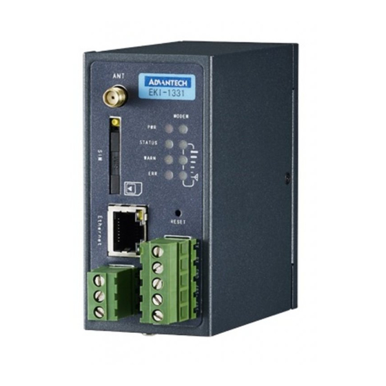
Page 11: Physical Characteristics
– Equipment Management Security Multi-level authorization security mechanism realizes centralized authentica- tion and authorization management of equipment. Physical Characteristics Housing: Steel, providing IP30 protection Dimensions (mm) Figure 1.1 DIN-Rail Mount Figure 1.2 Wall Mount EKI-1331 User Manual... - Page 12 EKI-1331 User Manual...
-
Page 13: Chapter 2 Login Gateway
Chapter Login Gateway Sections include: Establish Network Connection Test the connection between supervisory PC and EKI-1331 Cancel the Proxy Server... -
Page 14: Establish Network Connection
Please set the supervisory PC to “automatic acquisition of IP address” and “automatic acquisition of DNS server address”, which is the default configuration of Windows. This way, the EKI-1331 automatically assign an IP address to the super- visory PC using DHCP. - Page 15 Click the button <Local Connection> to enter the window “Local Connection Status”. Click <Properties> to enter the window “Local Connection Properties”, as shown below. EKI-1331 User Manual...
- Page 16 Select “Internet Protocol Version 4 (TCP/IPv4).” Click <Properties> to enter “Internet Protocol Version 4(TCP/IPv4) Properties.” Select “Obtain an IP address automatically” and “Obtain DNS Server address automatically,” then click <OK> to complete the process, as shown below. EKI-1331 User Manual...
-
Page 17: Set A Static Ip Address
Version 4 (TCP/IPv4) Properties” window. Then, select “Use the following IP address”, type the IP address (arbitrary value between 192.168.2.2 - 192.168.2.254), subnet mask (255.255.255.0), and default gateway (192.168.2.1) into the text boxes. Finally, click <OK> to finish setting a static IP, as shown below. EKI-1331 User Manual... -
Page 18: Test The Network Connection Between The Supervisory Pc And Eki
Enter “ping 192.168.2.1” and click the <OK> button. (192.168.2.1 is the default IP address of the EKI-1331). If the connection is good, you will see four returned packets. If there is no response, be sure to check your connection and your supervisory PC's network settings. -
Page 19: Disconnect From The Proxy Server
If the supervisory PC uses a proxy server to access the Internet, it is necessary to disconnect from the proxy and remove any proxy settings. The operating steps are as follows: Open Internet Explorer. Select Tools>>Internet Options to enter the window “Internet Options”. EKI-1331 User Manual... - Page 20 Select the tab “Connect” and click the button <LAN Setting (L)> to enter the win- dow “LAN Setting.” If the option “Use a Proxy Server for LAN” is checked, uncheck it. Click the <OK> button and continue to the web configuration section of the manual. EKI-1331 User Manual...
-
Page 21: Chapter 3 Configuration
Chapter Configuration Sections include: Logging in the Browser Inter- face System Network Service Firewall QoS Tools Status... -
Page 22: Login The Web Configuration Page Of Gateway
Caution! For security, it is highly recommended that you modify the default pass- word after your first login. Store the password information in a secure location. Click <Sync Time> to synchronize the gateway's clock with the system time of the host. EKI-1331 User Manual... -
Page 23: System
From the navigation panel, select System >> Basic Setup, then enter the “Basic Setup” page, as shown below. Page description is shown below: Parameters Description Default Language Select the language of configuration page English Hostname Set the name of EKI-1331 Gateway EKI-1331 User Manual... -
Page 24: Time
Display the system time of Gateway 2000-01-01 08:16:47 PC Time The current time of supervisory PC Timezone Set time zone Custom Custom TZ String Set the time zone of the Gateway CST-8 Auto update Time Time Update Interval Disabled EKI-1331 User Manual... -
Page 25: Serial Port
In client mode, the telnet cli- ent sends request to the telnet server, creating a session. While in server mode, the device supports Telnet connections for incoming clients, allowing for remote access. EKI-1331 User Manual... - Page 26 Enable Select to enable HTTP. Enabled Service Port Select management port. 80/443/23/N/A Enable—allow management of the EKI-1331 over the local network, or Local Access LAN. Enabled Disable—forbid management of the EKI-1331 over LAN. Enable—allow management of the EKI-1331 over the WAN, or internet.
-
Page 27: System Log
In “Non-privileged Users” section, we can create multiple user- names. Technicians can utilize multiple usernames while logging on a EKI-1331 via serial port or Telnet. 3.2.5 System Log A remote log server can be set through “System Log Settings,” and all system logs will be uploaded to the remote log server through the gateway. -
Page 28: Config Management
Parameters Description Default Gateway Configuration Import/Backup configuration Restore default configura- Click to reset EKI-1331. To complete the tion reset, users need to reboot the EKI-1331. The technician must configure the local Network Provider (ISP) APN, username, password, and other con- figs the same as their ISP. -
Page 29: System Upgrade
To upgrade the system, click the System, tab then <System upgrade> to enter upgrade page, then follow the steps below: Click <Browse> choose the upgrade file, and then click <Open>, as shown below: EKI-1331 User Manual... -
Page 30: Reboot
Click <Update> and then click <OK> to begin updating. Make sure your screen matches the picture below. Upgrade firmware succeed, and click <Reboot> to restart the EKI-1331. 3.2.8 Reboot If users need to reboot system, please click the System tab, then <Reboot> and click <OK>... -
Page 31: Logout
This section covers network settings include Dialup/Cellular, LAN, DNS, DDNS, and Static Routes. 3.3.1 Dialup/Cellular Connection With following configuration, EKI-1331 can access the internet through the wireless cellular network. From the navigation panel, select Network >> Dialup, then enter the “Dialup” tab, as shown below. - Page 32 Disable static IP address. It may be set to either “Always Online,” “Connect Connection Mode Always Online On Demand,” or “Manual.” When a dialup fails, EKI-1331 will redial after an Redial Interval 30 seconds interval. Advanced Options Initial Commands Used for advanced parameters.
- Page 33 PIN code Set the use of the SIM card PIN code. Set dialup timeout. The EKI-1331 will reboot after Dial Timeout 120 seconds timeout. Set max transmit unit, or max frame size. Set this number to 1500 for normal frames and larger for 1500 little big frames.
-
Page 34: Lan
Default or Manual. 1500 is the normal 1500 frame size for Ethernet v2. LAN Mode 100M Full/duplex,100M Half/duplex. Auto Negotiation Multi-IP Settings IP Address Set additional IP Address of LAN Netmask Set netmask of LAN Description Description about this IP address EKI-1331 User Manual... -
Page 35: Dns
Generally, users will only need to set the dialup DNS settings if they have static routes on the gateway. Page description is shown below: Parameters Description Default Primary DNS Set Primary DNS Secondary DNS Set Secondary DNS EKI-1331 User Manual... -
Page 36: Ddns
Registered hostname for DDNS Wildcard Set whether the server supports wildcards Disabled Whether to update the mailbox record Backup MX Whether to update the mailbox record Disabled Force Update Force update records after modifying the settings Disabled EKI-1331 User Manual... -
Page 37: Static Routes
Set IP address of the destination 0.0.0.0 Net Mask Set subnet mask of the destination 255.255.255.0 Gateway Set the gateway of the destination Interface Users can select which interface accesses the destination Description Describe a static route EKI-1331 User Manual... -
Page 38: Service
Windows Name Server Set the WINS binding. 0.0.0.0 (WINS) Static DHCP Set the MAC address of a designated IP MAC Address 00:00:00:00:00:00 address. IP address Set the static IP address of the host. 192.168.2.2 Host Set the hostname. EKI-1331 User Manual... -
Page 39: Dns Relay
When enabling DHCP, the DHCP relay is also enabled automati- cally. Relay cannot be disabled without disabling DHCP. While using dynamic DNS, the DNS relay service should be turned A maximum of twenty IP to domain-name pairs may be configured. EKI-1331 User Manual... -
Page 40: Vrrp: Virtual Router Redundancy Protocol
Virtual IP Set a Virtual IP address. Authentication Type Choose between "None" or Password type. None Virtual MAC Select to enable. Disable Select WAN to start monitoring WAN interface Monitor None traffic; select None do not monitor. EKI-1331 User Manual... -
Page 41: Dtu (Serial Port)
3.4.4 DTU (Serial Port) If you connect a serial device to EKI-1331, you need enable the DTU converter. EKI- 1331 can support a multi-protocol uplink to allow conversion of serial data and IP data. Users must select the correct serial mode on the window “Serial Port” from the navigation tab “System.”... -
Page 42: Modbus To Sms
RAM. These variables will be the SMS response sent after a query. After receiv- ing a control SMS, EKI-1331 sends the control command to the PLC and waits for a response. The response is sent from the PLC and then EKI-1331 sends the response to the user. -
Page 43: Sms Alarm Rules
SMS receiver in the alarm menu. The EKI-1331 will collect different variables depending on the alarm rules set by the user. When a variable matches the criteria, EKI-1331 will send an SMS alarm to all users on the “alarm user list,” along with a message. - Page 44 After enabling the “Modbus to SMS” function, EKI-1331 can identify two types of SMS commands sent by the users on the white list. The EKI-1331 performs an action corresponding to different commands and then sends a response to the SMS user.
- Page 45 The technician will match mathematical expressions and compare values to a vari- able in each rule. To set an alarm rule follow these steps: EKI-1331 User Manual...
- Page 46 20 or greater than or equal to 230, trigger the alarm and send the user-define SMS to the user ‘13810556243.’ In other words, when AB_VOLT is between 20 and 230, plc2 is in normal operat- ing conditions. EKI-1331 User Manual...
-
Page 47: Mbsms Variable Template
3.4.8 User can do a status check and reboot the EKI-1331 through SMS. After setting a user-defined message in the SMS config window, users can see the device's status or reboot the device. Statistics like signal strength, IP address, and uptime, among others, may be used to analyze the device. -
Page 48: Firewall
A firewall is necessary for blocking out malicious packets from the internet. On today's internet, security is more important than ever, which is why the EKI-1331 is well equipped to protecting the local network and provide a security barrier from external threats. -
Page 49: Filtering
Source Port Set the source port. Destination IP Set the destination IP address. Destination Port Set the destination port. Action Select either accept or block. Accept log can print the access IP address Disable Description Describe your configuration. EKI-1331 User Manual... -
Page 50: Port Mapping
3.5.3 Port Mapping The EKI-1331 support Network Address and Port Translation. It allows remote com- puters (for example, computers on the Internet) to connect to the local device that linked to LAN interface. To configure port mapping, go into the navigation panel, select Firewall >> Port Mapping, then enter “Port Mapping”... -
Page 51: Virtual Ip Mapping
IP Mapping, then enter the “Virtual IP Mapping” page, as shown below. Page description is shown below: Parameters Description Default Virtual IP for Gate- Set a virtual IP for the EKI-1331. Blank Source IP Range Set range of the external source IP addresses. Blank Virtual IP Set an external virtual IP. -
Page 52: Dmz (All Port Mapping)
Source Address Set a range of restricted source IP addresses. Blank Range The EKI-1331's management port should never be mapped to a DMZ. 3.5.6 MAC-IP Bundling When a firewall denies all access to the external network, only a PC with MAC-IP bundling can access the internet. -
Page 53: Qos
Control, then enter “Bandwidth Control” page, as shown below. The page description is shown below: Parameters Description Default Enable Check to enable. Disable Outbound Limit Max Set the maximum upload rate. 100000kbit/s Bandwidth Inbound Limit Max Set the download bandwidth limit. 100000kbit/s Bandwidth EKI-1331 User Manual... -
Page 54: Ip Bandwidth Limit
Description Default Enable Check to enable an IP bandwidth limiter. Enable IP Address Set the IP address to be limited. Rate(kbit/s) Set the bandwidth limit or rate. 100kbit/s Priority Set the priority. Medium Description Describe the configuration. EKI-1331 User Manual... -
Page 55: Tools
Tools The EKI-1331 comes with several tools to help admins diagnose network problems, including: Ping Trace route Link Speed Test 3.7.1 Ping Ping a tool many technicians are familiar with. It simply sends ICMP packets across the network to a remote host, and then retransmits an ICMP packet back to the origi- nal sender. -
Page 56: Trace Route
Advanced parameters 3.7.3 Link Speed Test The EKI-1331 uses a simple upload and download to test the link speed. To start the speed test, enter the navigation panel, select Tools>>Link Speed Test, then enter “Link Speed Test” page, as shown below. -
Page 57: Status
This page displays system statistics, including Name, Model, Current Version, Gateway Time, PC Time, UP Time, CPU Load, Memory Consumption, etc. Technicians may click the <Sync Time> button to synchronize the gateway with the system time of the host, as covered in the set-up chapter. EKI-1331 User Manual... -
Page 58: Modem
This page shows Modem status, including Signal Level, Register sta- tus, etc. 3.8.3 Network Connections From navigation panel, select Status >> Network Connections, then enter “Net- work Connections” page, as shown below. This page shows the connection status of Dialup and LAN. EKI-1331 User Manual... -
Page 59: Route Table
3.8.4 Route Table From navigation panel, select Status >> Route Table, then enter “Route Table” page, as shown below. This page shows the route table of EKI-1331. 3.8.5 Device List From navigation panel, select Status >> Device List, then enter “Device List” page, as shown below. -
Page 60: Log
3.8.7 From navigation panel, select Status >> Log, then enter “Log” page, as shown below. This page show system log, including Download Log File. EKI-1331 User Manual... -
Page 61: Installation Guide
Chapter Installation Guide... -
Page 62: Precautions
Humidity: 5 ~ 90% relative humidity (non-condensing) Avoid direct sunlight, away from heat sources or areas with strong electromag- netic interference. EKI-1331 need to be installed in an industrial DIN Rail. Please check whether installed the needed cables and connectors. ... -
Page 63: Din Rail Disassembly
Wall Mounting 4.3.1 Wall Mounting Installation Select the right installation location and make sure have enough space. Use a screwdriver to install the wall mounting plate in the rear of the EKI-1331. As shown in picture below: EKI-1331 User Manual... -
Page 64: Wall Mount Disassembly
SIM Card Installation EKI-1331 support dual card. Press the SIM card eject button and will pop up the cor- responding card slot. Insert a SIM card to the slot, as shown in figure below: EKI-1331 User Manual... -
Page 65: Antenna Installation
Fix the grounding ring of the ground wire to the grounding stud. Tighten the ground terminal nut. Caution! In order to improve anti-jamming capability of EKI-1331, the EKI-1331 must be grounded when using. According to the on-site environment, connect the ground wire to the ground stud of the EKI-1331. -
Page 66: Connect Cable
Connect Cable Connect EKI-1331 to PC directly with a network cable. Terminal connection The connection method of Serial interface are used industrial terminal connection, please connect the cable to the corresponding terminal inrerface before using. EKI-1331 provide two serial interface modes - RS232/RS485. -
Page 67: Appendix Afqa
Appendix... -
Page 68: Fqa
Whether the IP Address of your computer is the same subnet with EKI-1331 and the gateway address is EKI-1331 LAN address. EKI-1331 is powered on, have a ping to detect EKI-1331 from your PC and find packet loss? Please check if the network crossover cable is in good condition. - Page 69 EKI-1331? Check if the IP Address of the PC and EKI-1331 are in the same subnet and the gateway address is EKI-1331 LAN address. EKI-1331 is powered on, but can`t configure through the web interface? ...
- Page 70 EKI-1331 User Manual...
-
Page 71: Appendix B Description Of Led
Appendix Description of LED... -
Page 72: Description Of Led
Off Signal≤9 Signal(strong) Green On 31≥Signal≥20 Off Signal≤19 Some of the indicators are defined below: STATUS WARN ERROR Definition Power on Blink Initialization succeed Blink Blink Dialing Blink Dialing succeed Blink Blink Blink Upgrading Blink Blink Reset Succeed EKI-1331 User Manual... - Page 73 EKI-1331 User Manual...
- Page 74 No part of this publication may be reproduced in any form or by any means, electronic, photocopying, recording or otherwise, without prior written permis- sion of the publisher. All brand and product names are trademarks or registered trademarks of their respective companies. © Advantech Co., Ltd. 2015...
Need help?
Do you have a question about the EKI-1331 and is the answer not in the manual?
Questions and answers