
Related Manuals for Pickering PXI 40-597


Summary of Contents for Pickering PXI 40-597
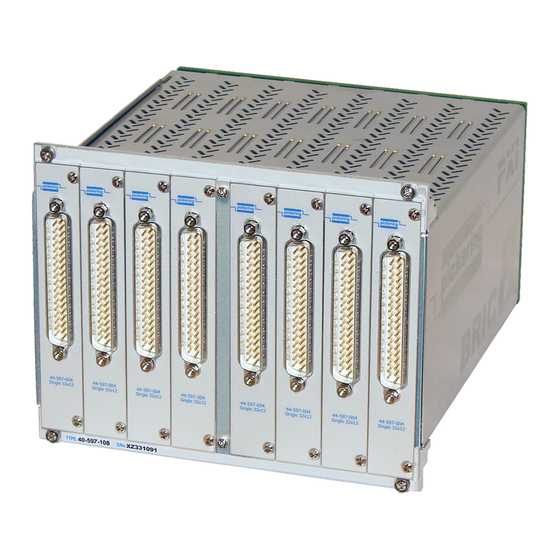
- Page 1 40-597 User Manual PXI 1-Pole 2 Amp BRIC™ Multi-Slot Matrix Module pickeringtest.com Issue 4.1 February 2020...
- Page 2 © COPYRIGHT (2020) PICKERING INTERFACES. ALL RIGHTS RESERVED. No part of this publication may be reproduced, transmitted, transcribed, translated or stored in any form, or by any means without the written permission of Pickering Interfaces. Technical details contained within this publication are subject to change without notice.
- Page 3 Pickering Interfaces strives to fulfil all relevant environmental laws and regulations and reduce wastes and releases to the environment. Pickering Interfaces aims to design and operate products in a way that protects the environment and the health and safety of its employees, customers and the public. Pickering Interfaces endeavours to develop and manufacture products that can be produced, distributed, used and recycled, or disposed of, in a safe and environmentally friendly manner.
-
Page 4: Product Safety
PRODUCT SAFETY SAFETY SYMBOLS The following safety symbols may be used on the product and throughout the product documentation. MEANING / DESCRIPTION SYMBOL PROTECTIVE EARTH (GROUND) To identify any terminal which is intended for connection to an external conductor for protection against electric shock in case of a fault, or the terminal of a protective earth (ground) electrode. -
Page 5: Table Of Contents
Section 4 Programming Guide ..............4.1 Programming Options for PXI Modules ......4.1 Module Architecture ..............4.2 Programming The Module ............4.3 Setting an X-X Connection ...........4.4 Using Pickering Drivers in LabVIEW ........4.5 Section 5 Connector Information ..............5.1 Section 6 Trouble Shooting .................6.1 Section 7 Maintenance Information ............7.1... - Page 6 THIS PAGE INTENTIONALLY BLANK 1-POLE 2A BRIC 3U PXI MULTI-SLOT MATRIX 40-597 Page (VI)
-
Page 7: Warnings And Cautions
Not to be used in safety critical circuits, refer to the Pickering Interfaces’ terms & conditions of sale. This module must not be used for the switching of Mains Circuits. For the switching of voltages up to the module’s full specification, Secondary Circuit power supplies and the Device Under Test must... - Page 8 CAUTION - PRODUCT DOCUMENTATION SYMBOL Suitably qualified & trained users should ensure that the accompanying documentation is fully read and understood before attempting to install or operate the product. SAFETY INSTRUCTIONS SAFETY INSTRUCTIONS All cleaning and servicing requires the equipment to be isolated and disconnected from the power source and user I/O signals (refer to the Maintenance Section).
-
Page 9: Technical Specification
Analog busing is housed within the module using a high performance screened analog bus backplane. Pickering can construct custom cable assemblies for all of our PXI modules, please contact sales office for further assistance. - Page 10 SECTION 1 - TECHNICAL SPECIFICATION pickering Overview 1-Pole 2 Amp BRIC Matrix – 40-597 X128 The 40-597 in BRIC2 Format is Available With The 40-597 in BRIC4 Format is Available With Matrix Matrix Configurations of 32x12 and 64x12 Configurations Between 32x12 and 128x12...
- Page 11 SECTION 1 - TECHNICAL SPECIFICATION pickering Specifications 1-Pole 2 Amp BRIC Matrix – 40-597 Relay Type Power Requirements - BRIC8 The 40-597 BRIC modules are fitted with electro-mechanical relays +3.3V +12V -12V (Palladium-Ruthenium, Gold Covered Bifurcated). 115mA 2.2A 35mA Switching Specification...
- Page 12 37-pin D-type Connector Accessories data Product Customization sheet where a complete list and documentation can be found for Pickering PXI modules are designed and manufactured on our own accessories, or refer to the Connection Solutions catalog. flexible manufacturing lines, giving complete product control and enabling simple customization to meet very specific requirements.
- Page 13 We provide a full range of supporting cable and connector solutions for all our switching products—20 connector families with 1200+ products. We offer everything from simple mating connectors to complex cables assemblies and terminal blocks. All assemblies are manufactured by Pickering and are guaranteed to mechanically and electrically mate to our modules. Connectors & Backshells...
- Page 14 1-Pole 2 Amp BRIC Matrix – 40-597 Programming Pickering provide kernel, IVI and VISA (NI & Keysight) drivers which are compatible with all Microsoft supported versions of Windows and popular older versions. For a list of all supporting operating systems, please see: pickeringtest.com/os...
-
Page 15: Technical Description
SECTION 2 - TECHNICAL DESCRIPTION pickering SECTION 2 - TECHNICAL DESCRIPTION MECHANICAL DESCRIPTION The 40-597 BRIC Module comprises an alloy chassis, 2 slot (BRIC2), 4 slot (BRIC4) or 8 slot (BRIC8) width, with an integral backplane which contains the interface circuitry and is fitted with 37-pin connectors for the matrix card assemblies.Up to 2 matrix cards (BRIC2), 4 matrix cards (BRIC4) or 8 matrix cards (BRIC8) can be plugged into the... - Page 16 SECTION 2 - TECHNICAL DESCRIPTION pickering FRONT PANEL CONNECTOR ANALOG BACKPLANE ISOLATION SUB-MATRIX CARD 1 SWITCHES FRONT PANEL CONNECTOR ISOLATION SUB-MATRIX CARD 2 SWITCHES FRONT PANEL CONNECTOR X225 X256 ISOLATION SUB-MATRIX CARD 8 SWITCHES Figure 2.2 - 40-597 BRIC Matrix: Switching Architecture 1-POLE 2A BRIC 3U PXI MULTI-SLOT MATRIX 40-597 Page 2.2...
- Page 17 SECTION 2 - TECHNICAL DESCRIPTION pickering 4-SLOT BACKPLANE MOTHER BOARD Y BUS Y ISOLATION RELAYS RELAY MATRIX COILS EEPROM X BUS RELAY DRIVERS U2 TO U9 CONTROL Y BUS Y BUS CONTROL RELAY MATRIX COILS RELAY DRIVERS U10 TO U17...
- Page 18 SECTION 2 - TECHNICAL DESCRIPTION pickering THIS PAGE INTENTIONALLY BLANK 1-POLE 2A BRIC 3U PXI MULTI-SLOT MATRIX 40-597 Page 2.4...
-
Page 19: Installation
Modular products require installation in a suitable PXI/LXI chassis. The module is designed for indoor use only. PREOPERATION CHECKS (UNPACKING) 1. Check the module for transport damage and report any damage immediately to Pickering Interfaces. Do not attempt to install the product if any damage is evident. -
Page 20: Hardware Installation
For a system comprising more than one chassis, turn ON the last chassis in the system followed by the penultimate, etc, and finally turn ON the external controller or chassis containing the system controller. 9. For Pickering Interfaces modular LXI installation there is no requirement to use any particular power up sequence. -
Page 21: Testing Operation
Figure 3.2 - General Soft Front Panel Icon A selector panel will appear, listing all installed Pickering PCI, PXI or LXI switch cards and resistor cards. Click on the card you wish to control, and a graphical control panel is presented allowing operation of the card. - Page 22 SECTION 3 - INSTALLATION pickering THIS PAGE INTENTIONALLY BLANK 1-POLE 2A BRIC 3U PXI MULTI-SLOT MATRIX 40-597 Page 3.4...
-
Page 23: Programming Guide
SECTION 4 - PROGRAMMING PROGRAMMING OPTIONS FOR PICKERING INTERFACES PXI MODULES For information on the installation and use of drivers and the programming of Pickering’s products in various software environments, please refer to the Software User Manual. This is available as a download from: https://www.pickeringtest.com/support/software-drivers-and-downloads... -
Page 24: Module Architecture
SECTION 4 - PROGRAMMING GUIDE pickering MODULE ARCHITECTURE The 40-597 is a high density 1-pole switching matrix constructed from 32x12 sub-matrix cards linked with an analog backplane. The 40-597 module can be fitted with 1 or 2 sub-matrix cards (BRIC2), between 1 and 4 sub-matrix cards (BRIC4) or between 1 and 8 sub-matrix cards (BRIC8). -
Page 25: Programming The Module
Once the drivers are installed the manual “Sys40Prg.pdf” and driver help files which fully describes these functions can be found in the Pickering folder(s) or the Pickering entries on your Start Menu. The card must be opened before use and closed after using the following function calls: Direct I/O Driver - Open with PIL_OpenCards or PIL_OpenSpecifiedCard and close with PIL_CloseCards or PIL_CloseSpecifiedCards respectively. -
Page 26: Setting An X-X Connection
To connect two X channels, a Y channel must be used to establish a path, so two commands must be issued to establish that path. To connect two X channels choose an unused Y channel then connect each X to that Y channel. Using the Pickering Direct I/O driver: The OPCrosspoint function takes row (Y) and column (X) as parameters: PIL_OpCrosspoint(CardNo, SubUnit, 1, 2 ,1);... -
Page 27: Using Pickering Drivers In Labview
USING PICKERING DRIVERS IN LabVIEW Most Pickering drivers include a LabVIEW wrapper to permit full operation of the Pickering product from the LabVIEW environment. These wrappers are normally installed to the current LabVIEW folder system during installation of the Pickering driver. - Page 28 SECTION 4 - PROGRAMMING GUIDE pickering THIS PAGE INTENTIONALLY BLANK 1-POLE 2A BRIC 3U PXI MULTI-SLOT MATRIX 40-597 Page 4.6...
-
Page 29: Connector Information
SECTION 5 - CONNECTOR INFORMATION pickering SECTION 5 - CONNECTOR INFORMATION Figures 5.1 shows the connector positioning for the 40-597 Matrix Module. Figures 5.2 to 5.9 provide the pinouts for the 37-pin D-type connectors on the individual matrix cards. In its minimum configuration, the matrix has a single matrix card in position 1. - Page 30 SECTION 5 - CONNECTOR INFORMATION pickering FP_GND FP_GND Figure 5.2 - 40-597 Matrix Card 1 Pinout Figure 5.3 - 40-597 Matrix Card 2 Pinout 37-pin Male D-type Connector 37-pin Male D-type Connector (viewed from front of module) (viewed from front of module)
- Page 31 SECTION 5 - CONNECTOR INFORMATION pickering X129 X161 X130 X162 X131 X163 X132 X164 X133 X165 X134 X166 X135 X167 X136 X168 X137 X169 X138 X170 X139 X171 X140 X172 X141 X173 X142 X174 X143 X175 X144 X176 X145 X177...
- Page 32 SECTION 5 - CONNECTOR INFORMATION pickering THIS PAGE INTENTIONALLY BLANK 1-POLE 2A BRIC 3U PXI MULTI-SLOT MATRIX 40-597 Page 5.4...
-
Page 33: Trouble Shooting
PCI configuration, highlighting any potential configuration problems. Specific details of all installed Pickering switch cards are included. All the installed Pickering switch cards should be listed in the “Pilpxi information” section - if one or more cards is missing it may be possible to determine the reason by referring to the PCI configuration dump contained in the report, but interpretation of this information is far from straightforward, and the best course is to contact Pickering support: support@pickeringtest.com, if possible... - Page 34 SECTION 6 - TROUBLE SHOOTING pickering THIS PAGE INTENTIONALLY BLANK 1-POLE 2A BRIC 3U PXI MULTI-SLOT MATRIX 40-597 Page 6.2...
-
Page 35: Maintenance Information
For PXI modules which are supported in one of Pickering Interfaces’ Modular LXI Chassis (such as the 60-102B and 60-103B) no module software update is required. If the module was introduced after the LXI chassis was manufactured the module may not be recognized, in this case the chassis firmware may need upgrading. -
Page 36: Relay Fault Finding
SECTION 7 - MAINTENANCE INFORMATION pickering RELAY FAULT FINDING In the event of a switch failure in the 40-597 module the following procedure will help locate which relays need replacing. The module uses through-hole relays that are straight forward to replace providing normal good practice is followed to avoid PCB damage. - Page 37 SECTION 7 - MAINTENANCE INFORMATION pickering RELAYS USED IN SIGNAL PATH - MATRIX CARD 1 (X1 TO X32) ISOLATION RELAYS MOTHER BOARD 1-POLE 2A BRIC 3U PXI MULTI-SLOT MATRIX 40-597 Page 7.3...
- Page 38 SECTION 7 - MAINTENANCE INFORMATION pickering RELAYS USED IN SIGNAL PATH - MATRIX CARD 2 (X33 TO X64) ISOLATION RELAYS MOTHER BOARD 1-POLE 2A BRIC 3U PXI MULTI-SLOT MATRIX 40-597 Page 7.4...
- Page 39 SECTION 7 - MAINTENANCE INFORMATION pickering RELAYS USED IN SIGNAL PATH - MATRIX CARD 3 (X65 TO X96) ISOLATION RELAYS MOTHER BOARD 1-POLE 2A BRIC 3U PXI MULTI-SLOT MATRIX 40-597 Page 7.5...
- Page 40 SECTION 7 - MAINTENANCE INFORMATION pickering RELAYS USED IN SIGNAL PATH - MATRIX CARD 4 (X97 TO X128) X100 X101 X102 X103 X104 X105 X106 X107 X108 X109 X110 X111 X112 X113 X114 X115 X116 X117 X118 X119 X120 X121...
- Page 41 SECTION 7 - MAINTENANCE INFORMATION pickering RELAYS USED IN SIGNAL PATH - MATRIX CARD 5 (X129 TO X160) X129 X130 X131 X132 X133 X134 X135 X136 X137 X138 X139 X140 X141 X142 X143 X144 X145 X146 X147 X148 X149 X150...
- Page 42 SECTION 7 - MAINTENANCE INFORMATION pickering RELAYS USED IN SIGNAL PATH - MATRIX CARD 6 (X161 TO X192) X161 X162 X163 X164 X165 X166 X167 X168 X169 X170 X171 X172 X173 X174 X175 X176 X177 X178 X179 X180 X181 X182...
- Page 43 SECTION 7 - MAINTENANCE INFORMATION pickering RELAYS USED IN SIGNAL PATH - MATRIX CARD 7 (X193 TO X224) X193 X194 X195 X196 X197 X198 X199 X200 X201 X202 X203 X204 X205 X206 X207 X208 X209 X210 X211 X212 X213 X214...
- Page 44 SECTION 7 - MAINTENANCE INFORMATION pickering RELAYS USED IN SIGNAL PATH - MATRIX CARD 8 (X225 TO X256) X225 X226 X227 X228 X229 X230 X231 X232 X233 X234 X235 X236 X237 X238 X239 X240 X241 X242 X243 X244 X245 X246...
- Page 45 SECTION 7 - MAINTENANCE INFORMATION pickering RL23 RL106 RL107 RL16 RL17 RL18 RL19 RL20 RL21 RL15 RL24 RL10 RL108 RL109 RL30 RL31 RL32 RL33 RL34 RL35 RL29 RL25 RL11 RL110 RL111 RL44 RL45 RL46 RL47 RL48 RL49 RL43 RL26 RL12 RL112 RL113...
-
Page 46: Module Removal From Chassis
SECTION 7 - MAINTENANCE INFORMATION pickering MODULE REMOVAL FROM CHASSIS Because the 40-597 module is not fitted with a PXI handle, the following procedure should be followed for the extraction of the BRIC module from the host chassis. The extraction handle and fixing screw supplied with the module are required for this process. - Page 47 SECTION 7 - MAINTENANCE INFORMATION pickering 4. Slacken the four screws securing the module into the host chassis as shown in Figure 7.7. These screws are in captive collars so don’t have to be fully removed but need to be loose (and still retained by the BRIC front panel) to allow extraction of the module.
-
Page 48: Card Removal From Bric
SECTION 7 - MAINTENANCE INFORMATION pickering CARD REMOVAL FROM BRIC The following procedure should be followed for the extraction of a matrix relay card from the 40-597 BRIC module. The card extraction handle supplied with the module is required for this process as shown in Figure 7.10. It should be noted that individual matrix cards can be removed from the BRIC sub-chassis without removing the entire BRIC from the host chassis. - Page 49 SECTION 7 - MAINTENANCE INFORMATION pickering 3. Fit the card extraction handle over the connector of the relay card to be removed as shown in Figure 7.12. Fasten the fixing screws of the extraction handle to the screwlocks of the D-type connector.
-
Page 50: Card Replacement
SECTION 7 - MAINTENANCE INFORMATION pickering CARD REPLACEMENT CAUTION THE BACKPLANE CONNECTORS ARE NOT PROVIDED WITH LOCATING GUIDES. IN THE FOLLOWING PROCEDURE IS IT IMPORTANT THAT THE RELAY CARD CONNECTOR IS ALIGNED WITH THE BACKPLANE CONNECTOR BEFORE THE MODULE IS PUSHED FULLY HOME.
Need help?
Do you have a question about the PXI 40-597 and is the answer not in the manual?
Questions and answers