
Related Manuals for Pickering PXi 41-720


Summary of Contents for Pickering PXi 41-720
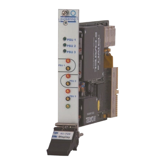
- Page 1 User Manual Isolated Power Supply Module (Model No. 41-720) Issue 6.7 July 2018 pickeringtest.com pickering PXI ISOLATED POWER SUPPLY MODULE 41-720 Page 1...
- Page 2 © COPYRIGHT (2018) PICKERING INTERFACES. ALL RIGHTS RESERVED. No part of this publication may be reproduced, transmitted, transcribed, translated or stored in any form, or by any means without the written permission of Pickering Interfaces. Technical details contained within this publication are subject to change without notice.
- Page 3 Pickering Interfaces strives to fulfil all relevant environmental laws and regulations and reduce wastes and releases to the environment. Pickering Interfaces aims to design and operate products in a way that protects the environment and the health and safety of its employees, customers and the public. Pickering Interfaces endeavours to develop and manufacture products that can be produced, distributed, used and recycled, or disposed of, in a safe and environmentally friendly manner.
-
Page 4: Product Safety
PRODUCT SAFETY SAFETY SYMBOLS The following safety symbols may be used on the product and throughout the product documentation. MEANING / DESCRIPTION SYMBOL PROTECTIVE EARTH (GROUND) To identify any terminal which is intended for connection to an external conductor for protection against electric shock in case of a fault, or the terminal of a protective earth (ground) electrode. -
Page 5: Table Of Contents
Software Installation ............ 3.2 Soft Front Panel Installation ........3.2 Section 4 Programming Guide ............4.1 Programming Options For Pickering PXI Cards..4.1 41-720 Module Architecture ......... 4.2 Programming The 41-720 Module ....... 4.3 Using Pickering Drivers in LabVIEW ......4.4 Using The Soft Front Panel ......... - Page 6 THIS PAGE INTENTIONALLY BLANK PXI ISOLATED POWER SUPPLY MODULE 41-720 Page vi...
-
Page 7: Warnings And Cautions
Unused slots in the PXI/LXI chassis are populated with blanking plates to prevent access to user I/O signals that may be present. Blanking panels are available to order from Pickering in a variety of slot widths. If the product is not used in this manner for example by using an extender card then additional care must be taken to avoid contact with exposed signals. - Page 8 THIS PAGE INTENTIONALLY BLANK PXI ISOLATED POWER SUPPLY MODULE 41-720 Page viii...
- Page 9 SECTION 1 - TECHNICAL SPECIFICATION pickering SECTION 1 - TECHNICAL SPECIFICATION 41-720 Isolated Power Supply ● One Slot Module Provides up to 4 Regulated Output Voltages ● Short Circuit and Thermally Protected ● Power On/Off Control for Each Regulated Output ●...
- Page 10 SECTION 1 - TECHNICAL SPECIFICATION pickering Width and Dimensions Power Consumption Occupies 1 slot of a 3U PXI chassis No current is taken from the PXI +3.3V supply or the ±12 Volt supplies. Connectors Current required from +5V PXI supply:...
-
Page 11: Technical Description
All modules are fully CE compliant and meet applicable EU Systems such as LabVIEW RT. For other RTOS support directives: Low-voltage safety EN61010-1:2001, contact Pickering. These drivers may be used with a variety of EMC Immunity EN61000-6-1:2001, Emissions EN55011:1998. programming environments and applications including: —... - Page 12 SECTION 2 - TECHNICAL DESCRIPTION pickering THIS PAGE INTENTIONALLY BLANK Page 2.4 PXI ISOLATED POWER SUPPLY MODULE 41-720...
-
Page 13: Functional Description
SECTION 2 - TECHNICAL DESCRIPTION pickering SECTION 2 - TECHNICAL DESCRIPTION FUNCTIONAL DESCRIPTION A functional block diagram is provided in Figure 2.1. The Module is powered by +5V and +12V inputs via Compact PCI connector J1. The interface to the user test equipment is via the front panel mounted 1mm connectors or a 9-pin D-type connector, J2. - Page 14 SECTION 2 - TECHNICAL DESCRIPTION pickering THIS PAGE INTENTIONALLY BLANK Page 2.2 PXI ISOLATED POWER SUPPLY MODULE 41-720...
-
Page 15: Installation
Modular products require installation in a suitable PXI/LXI chassis. The module is designed for indoor use only. PREOPERATION CHECKS (UNPACKING) 1. Check the module for transport damage and report any damage immediately to Pickering Interfaces. Do not attempt to install the product if any damage is evident. -
Page 16: Hardware Installation
For a system comprising more than one chassis, turn ON the last chassis in the system followed by the penultimate, etc, and finally turn ON the external controller or chassis containing the system controller. 9. For Pickering Interfaces modular LXI installation there is no requirement to use any particular power up sequence. -
Page 17: Soft Front Panel Installation
SECTION 3 - INSTALLATION pickering SOFTWARE INSTALLATION First install the appropriate Pickering PXI switch card drivers by running the installer program Setup.exe, either from the CD-ROM supplied, or by downloading the latest version from our website http://www.pickeringtest.com - the recommended method. There are different versions of the Setup program to suit different Windows versions and software environments. - Page 18 SECTION 3 - INSTALLATION pickering THIS PAGE INTENTIONALLY BLANK Page 3.4 PXI ISOLATED POWER SUPPLY MODULE 41-720...
-
Page 19: Programming Guide
SECTION 4 - PROGRAMMING GUIDE pickering SECTION 4 - PROGRAMMING GUIDE PROGRAMMING OPTIONS FOR PICKERING INTERFACES PXI CARDS Software drivers are supplied for Microsoft Windows operating systems, with specific support for the following development environments: Microsoft Visual Studio (VB, C++, C#) ●... -
Page 20: 41-720 Module Architecture
With most drivers, before programming a Pickering card it is important to understand the basic architecture of Pickering cards. The switches on a Pickering card are organized into logical sub-units, each sub-unit containing a set of objects of similar type and use. These objects may be switches, digital outputs, digital inputs, resistors, power supplies etc, depending on the nature of the specific card. -
Page 21: Programming The 41-720 Module
SECTION 4 - PROGRAMMING GUIDE pickering PROGRAMMING THE 41-720 MODULE Here are examples of using the drivers with the 41-720 (3-channel) Using PILPXI To operate a relay the user could use the simple OpBit command or the WriteSub commands OpBit DWORD sub_unit = 1;... -
Page 22: Using Pickering Drivers In Labview
USING PICKERING DRIVERS IN LabVIEW Most Pickering drivers include a LabVIEW wrapper to permit full operation of the Pickering product from the LabVIEW environment. These wrappers are normally installed to the current LabVIEW folder system during installation of the Pickering driver. -
Page 23: Using The Soft Front Panel
Figure 4.2 - Soft Front Panel For The 41-720 Isolated Power Supply Module As the software starts up it attempts to open any 41-720 modules installed in the system using the Pickering kernel driver ‘pilpxi.dll’. If this file cannot be found or is not the correct version then an error message will be displayed. - Page 24 SECTION 4 - PROGRAMMING GUIDE pickering THIS PAGE INTENTIONALLY BLANK PXI ISOLATED POWER SUPPLY MODULE 41-720 Page 4.6...
- Page 25 SECTION 5 - CONNECTOR INFORMATION pickering SECTION 5 - CONNECTOR INFORMATION pickering pickering PSU 1 PSU 1 PSU 2 PSU 2 PSU 3 PSU 3 PSU 1 OPTION YY +O/P PSU 3 PSU 1 OPTION YY +O/P OPTION XX +O/P...
- Page 26 SECTION 5 - CONNECTOR INFORMATION pickering THIS PAGE INTENTIONALLY BLANK Page 5.2 PXI ISOLATED POWER SUPPLY MODULE 41-720...
-
Page 27: Trouble Shooting
PCI configuration, highlighting any potential configuration problems. Specific details of all installed Pickering switch cards are included. All the installed Pickering switch cards should be listed in the “Pilpxi information” section - if one or more cards is missing it may be possible to determine the reason by referring to the PCI configuration dump contained in the report, but interpretation of this information is far from straightforward, and the best course is to contact Pickering support: support@pickeringtest.com, if possible... - Page 28 SECTION 6 - TROUBLE SHOOTING pickering THIS PAGE INTENTIONALLY BLANK Page 6.2 PXI ISOLATED POWER SUPPLY MODULE 41-720...
-
Page 29: Maintenance Information
For PXI modules which are supported in one of Pickering Interfaces’ Modular LXI Chassis (such as the 60-102B and 60-103B) no module software update is required. If the module was introduced after the LXI chassis was manufactured the module may not be recognized, in this case the chassis firmware may need upgrading. - Page 30 SECTION 7 - MAINTENANCE INFORMATION pickering THIS PAGE INTENTIONALLY BLANK Page 7.2 PXI ISOLATED POWER SUPPLY MODULE 41-720...
Need help?
Do you have a question about the PXi 41-720 and is the answer not in the manual?
Questions and answers