
Related Manuals for Pickering PXI 40-145


Summary of Contents for Pickering PXI 40-145
- Page 1 (217) 352-9330 | Click HERE Find the Pickering 40-145-201 at our website:...
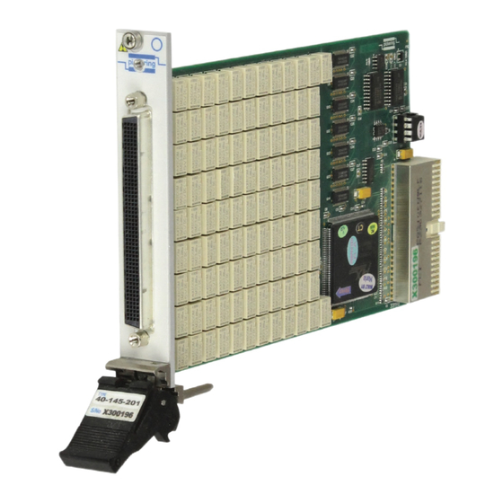
- Page 2 User Manual High Density SPST, DPST & SPDT Relay Modules (Model Nos. 40-145/146/148) Issue 5.4 August 2017 pickeringtest.com pickering HIGH DENSITY RELAY MODULES 40-145/146/148 Page (1) Artisan Technology Group - Quality Instrumentation ... Guaranteed | (888) 88-SOURCE | www.artisantg.com...
- Page 3 © COPYRIGHT (2017) PICKERING INTERFACES. ALL RIGHTS RESERVED. No part of this publication may be reproduced, transmitted, transcribed, translated or stored in any form, or by any means without the written permission of Pickering Interfaces. Technical details contained within this publication are subject to change without notice.
- Page 4 Pickering Interfaces strives to fulfil all relevant environmental laws and regulations and reduce wastes and releases to the environment. Pickering Interfaces aims to design and operate products in a way that protects the environment and the health and safety of its employees, customers and the public. Pickering Interfaces endeavours to develop and manufacture products that can be produced, distributed, used and recycled, or disposed of, in a safe and environmentally friendly manner.
-
Page 5: Product Safety
PRODUCT SAFETY SAFETY SYMBOLS The following safety symbols may be used on the product and throughout the product documentation. MEANING / DESCRIPTION SYMBOL PROTECTIVE EARTH (GROUND) To identify any terminal which is intended for connection to an external conductor for protection against electric shock in case of a fault, or the terminal of a protective earth (ground) electrode. -
Page 6: Table Of Contents
Hardware Installation ............3.2 Software Installation .............3.2 Testing Operation ..............3.3 Section 4 Programming Guide ..............4.1 Programming Options For Pickering PXI Cards....4.1 Module Architecture - 40-145-001/101/201 ......4.3 Module Architecture - 40-145-001/101/201-NC ....4.4 Module Architecture - 40-146-002/202 .........4.5 Module Architecture - 40-148-001/101/201 ......4.6 Programming The Module ............4.7... - Page 7 THIS PAGE INTENTIONALLY BLANK HIGH DENSITY RELAY MODULES 40-145/146/148 Page (VI) Artisan Technology Group - Quality Instrumentation ... Guaranteed | (888) 88-SOURCE | www.artisantg.com...
-
Page 8: Warnings And Cautions
Unused slots in the PXI/LXI chassis are populated with blanking plates to prevent access to user I/O signals that may be present. Blanking panels are available to order from Pickering in a variety of slot widths. If the product is not used in this manner for example by using an extender card then additional care must be taken to avoid contact with exposed signals. - Page 9 THIS PAGE INTENTIONALLY BLANK HIGH DENSITY RELAY MODULES 40-145/146/148 Page (VIII) Artisan Technology Group - Quality Instrumentation ... Guaranteed | (888) 88-SOURCE | www.artisantg.com...
- Page 10 (e.g. hermetically sealed so ensuring consistent and stable contact lamps, solenoids etc.). resistance with long life. All of the reed relays used in our PXI modules are manufactured by our sister company Pickering Range Description: Electronics: (www.pickeringrelay.com). 40-145 50, 75 or 100 x SPST Relays Pin Compatibility.
- Page 11 Pickering’s PXI switching products, simplifying servicing and reducing down-time. Product Relay Kit All Types 91-100-001 For further assistance, please contact your local Pickering sales office. Mating Connectors & Cabling For connection accessories for the 40-145 series please refer to the 90-002D...
- Page 12 All modules are fully CE compliant and meet applicable EU Systems such as LabVIEW RT. For other RTOS support directives: Low-voltage safety EN61010-1:2001, contact Pickering. These drivers may be used with a variety of EMC Immunity EN61000-6-1:2001, Emissions EN55011:1998. programming environments and applications including: —...
- Page 13 SECTION 1 - TECHNICAL SPECIFICATION pickering THIS PAGE INTENTIONALLY BLANK HIGH DENSITY RELAY MODULES 40-145/146/148 Page 1.4 Artisan Technology Group - Quality Instrumentation ... Guaranteed | (888) 88-SOURCE | www.artisantg.com...
-
Page 14: Technical Description
SECTION 2 - TECHNICAL DESCRIPTION pickering SECTION 2 - TECHNICAL DESCRIPTION FUNCTIONAL DESCRIPTION A functional block diagram is provided in Figure 2.1. The High Density Relay Module is powered by a +5V input via Compact PCI connector J1. The interface to the user test equipment is via the front panel mounted 200-pin LFH type connector, J2. -
Page 15: 40-145 - Guidance On Power Handling
SECTION 2 - TECHNICAL DESCRIPTION pickering 40-145 - GUIDANCE ON POWER HANDLING (PXI CHASSIS) The PXI standard recommends that each slot consumes less than 25 Watts to ensure that the chassis does not overheat. Some chassis may be capable of handling more than 25W per slot. - Page 16 ● switch as two closures. It should be noted that users with a Pickering Interfaces 40-908, 40-914 or 40-918 PXI chassis mounted in accordance with the user instructions ensuring free air flow, can expect a capacity of 40W per slot.
- Page 17 SECTION 2 - TECHNICAL DESCRIPTION pickering THIS PAGE INTENTIONALLY BLANK HIGH DENSITY RELAY MODULES 40-145/146/148 Page 2.4 Artisan Technology Group - Quality Instrumentation ... Guaranteed | (888) 88-SOURCE | www.artisantg.com...
-
Page 18: Installation
Modular products require installation in a suitable PXI/LXI chassis. The module is designed for indoor use only. PREOPERATION CHECKS (UNPACKING) 1. Check the module for transport damage and report any damage immediately to Pickering Interfaces. Do not attempt to install the product if any damage is evident. -
Page 19: Hardware Installation
For a system comprising more than one chassis, turn ON the last chassis in the system followed by the penultimate, etc, and finally turn ON the external controller or chassis containing the system controller. 9. For Pickering Interfaces modular LXI installation there is no requirement to use any particular power up sequence. -
Page 20: Testing Operation
Figure 3.2 - General Soft Front Panel Icon A selector panel will appear, listing all installed Pickering PCI, PXI or LXI switch cards and resistor cards. Click on the card you wish to control, and a graphical control panel is presented allowing operation of the card. - Page 21 SECTION 3 - INSTALLATION pickering THIS PAGE INTENTIONALLY BLANK HIGH DENSITY RELAY MODULES 40-145/146/148 Page 3.4 Artisan Technology Group - Quality Instrumentation ... Guaranteed | (888) 88-SOURCE | www.artisantg.com...
-
Page 22: Programming Guide
IVI Driver for Windows - pi40iv The pi40iv IVI (Interchangeable Virtual Instrument) driver supports all Pickering Interfaces PXI switch cards that are consistent with the Iviswtch class model - as are the great majority of cards in the System 40/45/50 ranges. It integrates well with LabWindows/CVI and LabVIEW, and is fully compatible with Switch Executive. - Page 23 Pickering LXI products include an SSH interface which allows remote command line access to control cards, or, using a suitable package, programmatic control. The user is advised to visit the Pickering web site for further details of all the above drivers, where documentation, example programs, and further help with driver choice are available.
- Page 24 SECTION 4 - PROGRAMMING GUIDE pickering MODULE ARCHITECTURE - 40-145 NORMALLY OPEN VERSIONS The 40-145-001/101/201 are arrays of 50, 75 or 100 uncommitted SPST relays. In the default state, all signal paths are open, energising a particular relay creates a signal path between the C and A terminals. The relay module’s...
- Page 25 SECTION 4 - PROGRAMMING GUIDE pickering MODULE ARCHITECTURE - 40-145 NORMALLY CLOSED VERSIONS The 40-145-001/101/201-NC are arrays of 50, 75 or 100 uncommitted SPST relays. In the default state, all signal paths are connected between the C and the corresponding B terminals, energising a particular relay disconnects the signal path The relay module’s switching architectures are shown in their default state in the diagram below:...
- Page 26 SECTION 4 - PROGRAMMING GUIDE pickering MODULE ARCHITECTURE - 40-146 The 40-146 is an array of 25 or 50 uncommitted DPST relays. In the default state, all signal paths are open. Energising a particular relay creates a signal path between the C and A terminals of both poles of the corresponding channel.
-
Page 27: Module Architecture - 40-145-001/101/201
SECTION 4 - PROGRAMMING GUIDE pickering MODULE ARCHITECTURE - 40-148 The 40-148 is an array of 32, 48 or 64 uncommitted changeover relays. In the default state, all signal paths are between the C terminal and the corresponding B terminal. Energising a particular relay disconnects the B terminal and creates a signal path between the C and A terminals. -
Page 28: Programming The Module
SECTION 4 - PROGRAMMING GUIDE pickering PROGRAMMING THE MODULE Here are examples of using the drivers with the 40-145-001 (50 x SPST) module. All other versions in the series operate in the same way but with different numbers of bits in the sub-unit. -
Page 29: Using Pickering Drivers In Labview
USING PICKERING DRIVERS IN LabVIEW Most Pickering drivers include a LabVIEW wrapper to permit full operation of the Pickering product from the LabVIEW environment. These wrappers are normally installed to the current LabVIEW folder system during installation of the Pickering driver. -
Page 30: Connector Information
SECTION 5 - CONNECTOR INFORMATION pickering SECTION 5 - CONNECTOR INFORMATION 146 A10 146 A10 145 C10 45 C12 145 C10 45 C12 144 A14 144 A14 143 C14 43 C16 143 C14 43 C16 142 A18 142 A18 141 C18... - Page 31 SECTION 5 - CONNECTOR INFORMATION pickering 146 A10 146 B10 145 C10 145 C10 45 C12 144 A14 144 B14 143 C14 143 C14 43 C16 142 A18 142 B18 141 C18 141 C18 41 C20 140 A22 140 B22...
- Page 32 SECTION 5 - CONNECTOR INFORMATION pickering 146 B10 146 B10 145 C10 145 C10 45 C12 144 B14 144 B14 143 C14 143 C14 43 C16 142 B18 142 B18 141 C18 141 C18 41 C20 140 B22 140 B22...
- Page 33 SECTION 5 - CONNECTOR INFORMATION pickering A1.1 C1.1 A2.1 C2.1 A1.1 C1.1 A2.1 C2.1 A1.2 C1.2 A2.2 C2.2 A1.2 C1.2 A2.2 C2.2 C3.1 C4.1 A3.1 A4.1 A3.1 C3.1 C4.1 A4.1 C4.2 A3.2 C3.2 A4.2 C3.2 C4.2 A3.2 A4.2 A5.1 C5.1 A6.1...
- Page 34 SECTION 5 - CONNECTOR INFORMATION pickering 32 x SPDT 48 x SPDT Figure 5.9 - Pinouts: 32xSPDT High Figure 5.10 - Pinouts: 48xSPDT High Density Relay Module 40-148-001 Density Relay Module 40-148-101 (200-pin female LFH connector (200-pin female LFH connector...
- Page 35 SECTION 5 - CONNECTOR INFORMATION pickering 64 x SPDT Figure 5.11 - Pinouts: 64xSPDT High Density Relay Module 40-148-201 (200-pin female LFH connector viewed from front of module) HIGH DENSITY RELAY MODULES 40-145/146/148 Page 5.6 Artisan Technology Group - Quality Instrumentation ... Guaranteed | (888) 88-SOURCE | www.artisantg.com...
-
Page 36: Trouble Shooting
PCI configuration, highlighting any potential configuration problems. Specific details of all installed Pickering switch cards are included. All the installed Pickering switch cards should be listed in the “Pilpxi information” section - if one or more cards is missing it may be possible to determine the reason by referring to the PCI configuration dump contained in the report, but interpretation of this information is far from straightforward, and the best course is to contact Pickering support: support@pickeringtest.com, if possible... - Page 37 SECTION 6 - TROUBLE SHOOTING pickering THIS PAGE INTENTIONALLY BLANK HIGH DENSITY RELAY MODULES 40-145/146/148 Page 6.2 Artisan Technology Group - Quality Instrumentation ... Guaranteed | (888) 88-SOURCE | www.artisantg.com...
-
Page 38: Maintenance Information
For PXI modules which are supported in one of Pickering Interfaces’ Modular LXI Chassis (such as the 60-102B and 60-103B) no module software update is required. If the module was introduced after the LXI chassis was manufactured the module may not be recognized, in this case the chassis firmware may need upgrading. - Page 39 SECTION 7 - MAINTENANCE INFORMATION pickering TABLE 7.1 - High Density Relay Module 40-145-001/101/201 (normally open) Relay Numbering Signal Path Signal Path Relay No. Relay No. Relay No. Relay No. Relay No. Relay No. (with relay (with relay 40-145-001 40-145-101...
- Page 40 SECTION 7 - MAINTENANCE INFORMATION pickering TABLE 7.2 - High Density Relay Module 40-145-001/101/201-NC (normally closed) Relay Numbering Signal Path Relay No. Relay No. Relay No. Signal Path Relay No. Relay No. Relay No. (with relay 40-145-001 40-145-101 40-145-201 (with relay...
- Page 41 SECTION 7 - MAINTENANCE INFORMATION pickering Figure 7.1 - 40-145 High Density Relay Module Component Layout HIGH DENSITY RELAY MODULES 40-145/146/148 Page 7.4 Artisan Technology Group - Quality Instrumentation ... Guaranteed | (888) 88-SOURCE | www.artisantg.com...
- Page 42 SECTION 7 - MAINTENANCE INFORMATION pickering TABLE 7.3 - High Density Relay Module 40-146-002/202 Relay Numbering Signal Path Relay No. Relay No. (with relay energised) 40-146-002 40-146-202 C1.1 to A1.1 & C1.2 to A1.2 C2.1 to A2.1 & C2.2 to A2.2 C3.1 to A3.1 &...
- Page 43 SECTION 7 - MAINTENANCE INFORMATION pickering RL10 RL11 RL12 RL13 RL14 RL15 RL16 RL17 RL18 RL20 RL21 RL22 RL23 RL24 RL19 RL25 RL26 RL27 RL28 RL29 RL30 RL31 RL32 RL33 RL34 RL35 RL36 RL38 RL39 RL40 RL41 RL42 RL37 RL43...
- Page 44 SECTION 7 - MAINTENANCE INFORMATION pickering TABLE 7.4 - High Density Relay Module 40-148-001/101/201 Relay Numbering Signal Path Signal Path Relay No. Relay No. Relay No. (with relay energised) (with relay de-energised) 40-148-001 40-148-101 40-148-201 C1 to A1 C1 to B1...
- Page 45 SECTION 7 - MAINTENANCE INFORMATION pickering Figure 7.3 - 40-148 High Density Relay Module Component Layout HIGH DENSITY RELAY MODULES 40-145/146/148 Page 7.8 Artisan Technology Group - Quality Instrumentation ... Guaranteed | (888) 88-SOURCE | www.artisantg.com...
Need help?
Do you have a question about the PXI 40-145 and is the answer not in the manual?
Questions and answers