Advertisement
Quick Links
Advertisement

Related Manuals for Pickering PXI 41-181


Summary of Contents for Pickering PXI 41-181
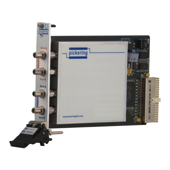
- Page 1 USER MANUAL 2.3GHz PROGRAMMABLE STEP ATTENUATOR MODULE (MODEL No. 41-181) Issue E July 2012 NOTE: Provided for information only. Use 41-180 for all new requirements. www.pickeringtest.com ISO 9002 pickering Reg No. FM38792 2.3GHz ProGrammable SteP attenuator module 41-181 Page 1...
- Page 2 © COPyRIght (2012) PICkERINg INtERFACES. ALL RIghtS RESERvEd. No part of this publication may be reproduced, transmitted, transcribed, translated or stored in any form, or by any means without the written permission of Pickering Interfaces. Technical details contained within this publication are subject to change without notice.
- Page 3 Pickering Interfaces strives to fulfil all relevant environmental laws and regulations and reduce wastes and releases to the environment. Pickering Interfaces aims to design and operate products in a way that protects the environment and the health and safety of its employees, customers and the public. Pickering Interfaces endeavours to develop and manufacture products that can be produced, distributed, used and recycled, or disposed of, in a safe and environmentally friendly manner.
- Page 4 THIS PAGE INTENTIONALLY BLANK 2.3GHz ProGrammable SteP attenuator module 41-181 Page iv...
-
Page 5: Table Of Contents
CONtENtS Copyright Statement ............ii technical Support and Warranty ........iii Contents (this page) ............v Section 1 Introduction ................. 1.1 Section 2 Technical Specification ............2.1 Section 3 Installation ................3.1 Section 4 Programming ..............4.1 Section 5 Connector Pin Outs ............ - Page 6 THIS PAGE INTENTIONALLY BLANK 2.3GHz ProGrammable SteP attenuator module 41-181 Page vi...
-
Page 7: Introduction
Section 1 - introduction pickering SECtION 1 - INtROdUCtION gENERAL The 41-181 Programmable 0 to 63 dB Attenuator Module which forms part of the System 40 PXI RF Instrumentation range comprises either one or two independently programmable attenuators in a single width 3U PXI module. Each attenuator comprises seven attenuator pads ranging in value from 1 dB to 16dB. - Page 8 Section 1 - introduction pickering THIS PAGE INTENTIONALLY BLANK Page 1.2 2.3GHz ProGrammable SteP attenuator module 41-181...
- Page 9 Section 2 - SPeciFicAtion pickering SECtION 2 - SPECIFICAtION gENERAL ChARACtERIStICS Frequency range: DC to 2.3 GHz Maximum Input Power: 1 Watt continuous Input Impedance: 50 ohms, DC coupled VSWR (SMA connector): Less than 1.5, Typically less than 1.3 typical Crosstalk versus Frequency With No Attenuation Set AttENUAtION The attenuator is made up 1, 2, 4, 8 and 16 (3 off) switched pads, attenuator set to 0 dB with no power applied.
- Page 10 Section 2 - SPeciFicAtion pickering typical Insertion Loss versus Frequency (0 dB Set) Attenuation accuracy versus frequency, 8 dB set. 2.3GHz ProGrAmmAble SteP AttenuAtor module 41-181 Page 2.2...
- Page 11 Section 2 - SPeciFicAtion pickering Attenuation accuracy versus frequency, 32 dB set Attenuation accuracy with 48 dB selected 2.3GHz ProGrammable SteP attenuator module 41-181 Page 2.3...
- Page 12 Section 2 - SPeciFicAtion pickering Attenuation accuracy versus frequency, 63 dB set Physical Parameters Size: Single width 3U PXI/cPCI instrument module PXI Supply Consumption +12 Volt +5 Volt +3.3 Volt -12 Volt 0.2 Amps 0.1 Amps Connectors PXI bus via 32 bit P1/J1 backplane connector. RF Signals via a front panel SMA connectors.
-
Page 13: Installation
Section 3 - inStALLAtion pickering SECtION 3 - INStALLAtION SOFtWARE INStALLAtION First install the appropriate Pickering PXI card drivers by running the installer program Setup.exe, either from the CD-ROM supplied, or by downloading the latest version from our website http://www.pickeringtest.com - the recommended method. - Page 14 Start the Test Panels application from the Programs>>Pickering>>PXI Utilities menu. If you are a LabVIEW user, run “Test Panels (LabVIEW VI)”; if not, run “Test Panels (EXE)”. A selector panel will appear, listing all installed Pickering PXI cards. Click on the card you wish to control, and a graphical control panel is presented allowing operation of the card.
- Page 15 As an alternative to the Test Panels, the simple Terminal Monitor program PILMon (again on the Programs>>Pickering>>PXI Utilities menu) allows access to all functions of Pickering cards through a command- line interface. In PILMon, enter “HE” for help on it’s commands.
- Page 16 PROgRAMMABLE AttENUAtOR SOFt FRONt PANEL A dedicated Soft Front Panel application is available on the Pickering distribution disk and from the Pickering web- site. On the disk it can be found in the /Applications/Soft Front Panels/ folder, on the web-site it is located at: http://downloads.pickeringtest.info/downloads/Soft_Front_Panels/Programmable%20Attenuator%20v1.1.2.exe...
-
Page 17: Programming
IvI driver for Windows - pi40iv The pi40iv IVI (Interchangeable Virtual Instrument) driver supports all Pickering Interfaces PXI switch cards that are consistent with the Iviswtch class model - as are the great majority of cards in the System 40/45/50 ranges. It integrates well with LabWindows/CVI and LabVIEW, and is fully compatible with Switch Executive. - Page 18 Pickering LXI products include an SSH interface which allows remote command line access to control cards, or, using a suitable package, programmatic control. The user is advised to visit the Pickering web site for further details of all the above drivers, where documentation, example programs, and further help with driver choice are available.
- Page 19 Once the drivers are installed the manual “Sys40Prg.pdf” and driver help files which fully describes these functions can be found in the Pickering folder(s) or the Pickering entries on your Start Menu. The card must be opened before use and closed after using the following function calls: Direct Driver - Open with PIL_OpenCards or PIL_OpenSpecifiedCard and close with PIL_CloseCards or PIL_CloseSpecifiedCards respectively.
- Page 20 USINg PICkERINg dRIvERS IN LabvIEW Most Pickering drivers include a LabVIEW wrapper to permit full operation of the Pickering product from the LabVIEW environment. These wrappers are normally installed to the current LabVIEW folder system during installation of the Pickering driver.
-
Page 21: Connector Pin Outs
Section 5 - Pin oUtS pickering SECtION 5 - CONNECtOR PIN OUtS Figure 5.1 provides pin outs for the Modules in the 41-181 model range. PORT A PORT B PORT A PORT B Figure 5.1 - Module: Pin Out Page 5.1... - Page 22 Section 5 - Pin oUtS pickering THIS PAGE INTENTIONALLY BLANK Page 5.2 2.3GHz ProGrammable SteP attenUator modUle 41-181...
-
Page 23: Troubleshooting
PCI configuration, highlighting any potential configuration problems. Specific details of all installed Pickering cards are included. All the installed Pickering cards should be listed in the “Pilpxi information” section - if one or more cards is missing it may be possible to determine the reason by referring to the PCI configuration dump contained in the report, but interpretation of this information is far from straightforward, and the best course is to contact Pickering support: support@pickeringtest.com, if possible including a copy of the... - Page 24 Section 6 - tRoUBLeSHootinG pickering THIS PAGE INTENTIONALLY BLANK Page 6.2 2.3GHz PRoGRammaBLe SteP attenUatoR modULe 41-181...
-
Page 25: General Description
Section 7 - FUnctionAL DeScRiPtion pickering SECtION 7 - gENERAL dESCRIPtION The 40-181 Programmable 0 to 63 dB Attenuator Module which forms part of the System 40 PXI RF Instrumentation range comprises either one or two independently programmable attenuators in a single width 3U PXI module. Each attenuator comprises seven attenuator pads ranging in value from 1 dB to 16dB. - Page 26 Section 7 - FUnctionAL DeScRiPtion pickering THIS PAGE INTENTIONALLY BLANK Page 7.2 2.3GHz PRoGRAmmAbLe SteP AttenUAtoR moDULe 41-181...
-
Page 27: Warnings And Cautions
SECtION 8 - WARNINgS ANd CAUtIONS WARNINg – hAZARdOUS ENvIRONMENtS This product is not specifically designed for use in hazardous environments, for example in explosive atmospheres. If the product is to be used in hazardous environments we recommend that the user ensures suitable protective measures are taken. - Page 28 THIS PAGE INTENTIONALLY BLANK Page 8.2 2.3GHz ProGrammable SteP attenuator module 41-181...
Need help?
Do you have a question about the PXI 41-181 and is the answer not in the manual?
Questions and answers