Table of Contents
Advertisement
Quick Links
Advertisement
Table of Contents

Related Manuals for Pickering PXI 40-795-001


Summary of Contents for Pickering PXI 40-795-001
- Page 1 Artisan Technology Group is your source for quality new and certified-used/pre-owned equipment SERVICE CENTER REPAIRS WE BUY USED EQUIPMENT • FAST SHIPPING AND DELIVERY Experienced engineers and technicians on staff Sell your excess, underutilized, and idle used equipment at our full-service, in-house repair center We also offer credit for buy-backs and trade-ins •...
- Page 2 User Manual 8/16 Tributary Daisy Chain Switch, Balanced (Model Nos. 40-795-001 / 40-796-001) Issue 3.2 May 2017 pickeringtest.com pickering 8/16 TRIBUTARY DAISY CHAIN SWITCH, BALANCED 40-795/796 Page (1) Artisan Technology Group - Quality Instrumentation ... Guaranteed | (888) 88-SOURCE | www.artisantg.com...
- Page 3 © COPYRIGHT (2017) PICKERING INTERFACES. ALL RIGHTS RESERVED. No part of this publication may be reproduced, transmitted, transcribed, translated or stored in any form, or by any means without the written permission of Pickering Interfaces. Technical details contained within this publication are subject to change without notice.
- Page 4 Pickering Interfaces strives to fulfil all relevant environmental laws and regulations and reduce wastes and releases to the environment. Pickering Interfaces aims to design and operate products in a way that protects the environment and the health and safety of its employees, customers and the public. Pickering Interfaces endeavours to develop and manufacture products that can be produced, distributed, used and recycled, or disposed of, in a safe and environmentally friendly manner.
-
Page 5: Product Safety
PRODUCT SAFETY SAFETY SYMBOLS The following safety symbols may be used on the product and throughout the product documentation. MEANING / DESCRIPTION SYMBOL PROTECTIVE EARTH (GROUND) To identify any terminal which is intended for connection to an external conductor for protection against electric shock in case of a fault, or the terminal of a protective earth (ground) electrode. -
Page 6: Table Of Contents
Pre Operation Checks ............3.1 Hardware Installation .............3.2 Software Installation ..............3.2 Testing Operation ..............3.3 Section 4 Programming Guide ..............4.1 Programming Options For Pickering PXI Cards....4.1 Module Architecture 40-795/796 ..........4.3 Programming The Module 40-795/796 .........4.9 Sub-unit Schematics ..............4.10 Signal Routing Examples ............4.12 Section 5 Connector Information ..............5.1... - Page 7 THIS PAGE INTENTIONALLY BLANK 8/16 TRIBUTARY DAISY CHAIN SWITCH, BALANCED 40-795/796 Page (VI) Artisan Technology Group - Quality Instrumentation ... Guaranteed | (888) 88-SOURCE | www.artisantg.com...
-
Page 8: Warnings And Cautions
Unused slots in the PXI/LXI chassis are populated with blanking plates to prevent access to user I/O signals that may be present. Blanking panels are available to order from Pickering in a variety of slot widths. If the product is not used in this manner for example by using an extender card then additional care must be taken to avoid contact with exposed signals. - Page 9 THIS PAGE INTENTIONALLY BLANK 8/16 TRIBUTARY DAISY CHAIN SWITCH, BALANCED 40-795/796 Page (VIII) Artisan Technology Group - Quality Instrumentation ... Guaranteed | (888) 88-SOURCE | www.artisantg.com...
-
Page 10: Technical Specification
7-slot PXI chassis can contain a 112 SDH/SONET Tributary Testing is a very specialised tributary switching system and an 18-slot PXI chassis can area, please contact Pickering Interfaces for additional contain up to 272 tributaries. application information and to discuss your exact The Daisy Chain Switching Module allows traffic to be requirements. - Page 11 <0.25dB to 10MHz Spare Relay Kits Daisy Chain: <0.5dB (40-795) and Kits of replacement relays are available for the majority of Pickering’s <1dB (40-796) to 10MHz PXI switching modules, simplifying servicing and reducing down-time. VSWR The relay kits for the 40-795/796 range are as follows: Test Signal to Rx/Tx: <1.3 to 10MHz...
- Page 12 All modules are fully CE compliant and meet applicable EU Systems such as LabVIEW RT. For other RTOS support directives: Low-voltage safety EN61010-1:2001, contact Pickering. These drivers may be used with a variety of EMC Immunity EN61000-6-1:2001, Emissions EN55011:1998. programming environments and applications including: —...
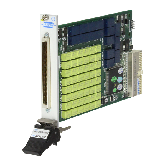
- Page 13 SECTION 1 - TECHNICAL SPECIFICATION pickering PCB Layout for the 40-796 16-Tributary Daisy-Chain Switch Module showing Mother and Daughter cards. The 8-tributary version (40-795) consists of the Mother card only. 8/16 TRIBUTARY DAISY CHAIN SWITCH, BALANCED 40-795/796 Page 1.4 Artisan Technology Group - Quality Instrumentation ... Guaranteed | (888) 88-SOURCE | www.artisantg.com...
-
Page 14: Technical Description
SECTION 2 - TECHNICAL DESCRIPTION pickering SECTION 2 - TECHNICAL DESCRIPTION FUNCTIONAL DESCRIPTION A functional block diagram is provided in Figure 2.1. The Daisy Chain Module is powered by a +5V input via Compact PCI connector J1. The interface to the user test equipment is via the front panel mounted 96-pin micro-D connector, J2. - Page 15 SECTION 2 - TECHNICAL DESCRIPTION pickering RL39, 40, 43, LINE 44, 45, 46, DRIVER 47, 48 RL33, 34, 35, LINE 36, 37, 38, DRIVER 41, 42 RL27, 28, 31, LINE 32, 122, 123, DRIVER 125, 126 RL25, 26, 29, LINE...
-
Page 16: Relay Schematic
SECTION 2 - TECHNICAL DESCRIPTION pickering To Next Page RL46 SUB-UNIT 2, Ch8 RL48 RL45 To Next Page RL47 RL44 SUB-UNIT 1, Ch8 RL43 RL107 RL101 RL111 RL40 SUB-UNIT 2, Ch7 RL42 RL110 RL102 RL39 RL108 RL41 RL103 RL38 SUB-UNIT 1, Ch7... - Page 17 SECTION 2 - TECHNICAL DESCRIPTION pickering Daisy Out Ch16 RL94 SUB-UNIT 2, Ch16 RL96 RL93 RL95 RL92 SUB-UNIT 1, Ch16 RL91 Ch15 RL88 SUB-UNIT 2, Ch15 RL90 RL87 RL89 RL86 SUB-UNIT 1, Ch15 RL85 Ch14 RL82 SUB-UNIT 2, Ch14 RL84...
-
Page 18: Installation
Modular products require installation in a suitable PXI/LXI chassis. The module is designed for indoor use only. PREOPERATION CHECKS (UNPACKING) 1. Check the module for transport damage and report any damage immediately to Pickering Interfaces. Do not attempt to install the product if any damage is evident. -
Page 19: Hardware Installation
For a system comprising more than one chassis, turn ON the last chassis in the system followed by the penultimate, etc, and finally turn ON the external controller or chassis containing the system controller. 9. For Pickering Interfaces modular LXI installation there is no requirement to use any particular power up sequence. -
Page 20: Testing Operation
Figure 3.2 - General Soft Front Panel Icon A selector panel will appear, listing all installed Pickering PCI, PXI or LXI switch cards and resistor cards. Click on the card you wish to control, and a graphical control panel is presented allowing operation of the card. - Page 21 SECTION 3 - INSTALLATION pickering THIS PAGE INTENTIONALLY BLANK 8/16 TRIBUTARY DAISY CHAIN SWITCH, BALANCED 40-795/796 Page 3.4 Artisan Technology Group - Quality Instrumentation ... Guaranteed | (888) 88-SOURCE | www.artisantg.com...
-
Page 22: Programming Guide
IVI Driver for Windows - pi40iv The pi40iv IVI (Interchangeable Virtual Instrument) driver supports all Pickering Interfaces PXI switch cards that are consistent with the Iviswtch class model - as are the great majority of cards in the System 40/45/50 ranges. It integrates well with LabWindows/CVI and LabVIEW, and is fully compatible with Switch Executive. - Page 23 Pickering LXI products include an SSH interface which allows remote command line access to control cards, or, using a suitable package, programmatic control. The user is advised to visit the Pickering web site for further details of all the above drivers, where documentation, example programs, and further help with driver choice are available.
-
Page 24: Module Architecture 40-795/796
SECTION 4 - PROGRAMMING GUIDE pickering MODULE ARCHITECTURE 40-795/796 Both module types use 2 Form C changeover relays. The 40-795 utilises an effective array of 64 relays and the 40-796 an effective array of 126 relays. In the default state the daisy chain is routed through all tributaries and the multiplexers are inactive. - Page 25 SECTION 4 - PROGRAMMING GUIDE pickering Table 4.1 - Sub-Units 1, 2 and 5 on a Single Channel of the 40-795/796 Sub-Unit 1 Sub-Unit 2 Sub-Unit 5 Routing In ➞ Rx Tx ➞ Out Rx MUX, Tx MUX disconnected In disconnected Tx ➞...
- Page 26 SECTION 4 - PROGRAMMING GUIDE pickering TABLE 4.2 - Daisy Chain Switch 40-795: Sub-Units 40-795 SUB-UNIT 1 - Rx Route SUB-UNIT 3 - Rx MUX Bit No. Function Relay No. Bit No. Function Relay No. Channel 1, Relay 1 Channel 1, Relay 1...
- Page 27 SECTION 4 - PROGRAMMING GUIDE pickering TABLE 4.3 - Daisy Chain Switch 40-796: Sub-Units 40-796 SUB-UNIT 1 - Rx Route SUB-UNIT 2 - Tx Route Bit No. Function Relay No. Bit No. Function Relay No. Channel 1, Relay 1 Channel 1, Relay 1...
- Page 28 SECTION 4 - PROGRAMMING GUIDE pickering TABLE 4.4 - Daisy Chain Switch 40-796: Sub-Units (continued) 40-796 SUB-UNIT 3 - Rx MUX SUB-UNIT 4 - Tx MUX Bit No. Function Relay No. Bit No. Function Relay No. Channel 1, Relay 1...
- Page 29 SECTION 4 - PROGRAMMING GUIDE pickering TABLE 4.5 - Daisy Chain Switch 40-796: Sub-Units (continued) 40-796 SUB-UNIT 5 - Rx/Tx Link Bit No. Function Relay No. Channel 1, Relay 1 Channel 1, Relay 2 Channel 2, Relay 1 RL11 Channel 2, Relay 2...
-
Page 30: Programming The Module 40-795/796
SECTION 4 - PROGRAMMING GUIDE pickering PROGRAMMING THE MODULE 40-795/796 Here are some simple examples of using the drivers with the Daisy Chain section of the 40-795 module. Using the drivers with the 40-796 module is similar. Using PILPXI To operate a relay the user could use the simple OpBit command or the WriteSub commands OpBit DWORD sub_unit = 1;... -
Page 31: Sub-Unit Schematics
SECTION 4 - PROGRAMMING GUIDE pickering To Next Page RL46 SUB-UNIT 2, Ch8 RL48 RL45 To Next Page RL47 RL44 SUB-UNIT 1, Ch8 RL43 RL107 RL101 RL111 RL40 SUB-UNIT 2, Ch7 RL42 RL110 RL102 RL39 RL108 RL41 RL103 RL38 SUB-UNIT 1, Ch7... - Page 32 SECTION 4 - PROGRAMMING GUIDE pickering Daisy Out Ch16 RL94 SUB-UNIT 2, Ch16 RL96 RL93 RL95 RL92 SUB-UNIT 1, Ch16 RL91 Ch15 RL88 SUB-UNIT 2, Ch15 RL90 RL87 RL89 RL86 SUB-UNIT 1, Ch15 RL85 Ch14 RL82 SUB-UNIT 2, Ch14 RL84...
-
Page 33: Signal Routing Examples
SECTION 4 - PROGRAMMING GUIDE pickering 40-795/796 Signal Routing Examples To Channels 9 to 16 (40-796 only) RL46 SUB-UNIT 2, Ch8 RL48 RL45 To Next Page RL47 RL44 SUB-UNIT 1, Ch8 RL43 RL107 RL101 RL111 RL40 SUB-UNIT 2, Ch7 RL42... - Page 34 SECTION 4 - PROGRAMMING GUIDE pickering To Channels 9 to 16 (40-796 only) RL46 SUB-UNIT 2, Ch8 RL48 RL45 To Next Page RL47 RL44 SUB-UNIT 1, Ch8 RL43 RL107 RL101 RL111 RL40 SUB-UNIT 2, Ch7 RL42 RL110 RL102 RL39 RL108...
- Page 35 SECTION 4 - PROGRAMMING GUIDE pickering THIS PAGE INTENTIONALLY BLANK 8/16 TRIBUTARY DAISY CHAIN SWITCH, BALANCED 40-795/796 Page 4.14 Artisan Technology Group - Quality Instrumentation ... Guaranteed | (888) 88-SOURCE | www.artisantg.com...
- Page 36 SECTION 5 - CONNECTOR INFORMATION pickering SECTION 5 - CONNECTOR INFORMATION TX 1.1 RX 1.1 TX 1.1 RX 1.1 TX 1.2 RX 1.2 TX 1.2 RX 1.2 RX 2.1 RX 2.1 TX 2.1 TX 2.1 RX 2.2 RX 2.2 TX 2.2 TX 2.2...
- Page 37 SECTION 5 - CONNECTOR INFORMATION pickering THIS PAGE INTENTIONALLY BLANK 8/16 TRIBUTARY DAISY CHAIN SWITCH, BALANCED 40-795/796 Page 5.2 Artisan Technology Group - Quality Instrumentation ... Guaranteed | (888) 88-SOURCE | www.artisantg.com...
-
Page 38: Trouble Shooting
PCI configuration, highlighting any potential configuration problems. Specific details of all installed Pickering switch cards are included. All the installed Pickering switch cards should be listed in the “Pilpxi information” section - if one or more cards is missing it may be possible to determine the reason by referring to the PCI configuration dump contained in the report, but interpretation of this information is far from straightforward, and the best course is to contact Pickering support: support@pickeringtest.com, if possible... - Page 39 SECTION 6 - TROUBLE SHOOTING pickering THIS PAGE INTENTIONALLY BLANK 8/16 TRIBUTARY DAISY CHAIN SWITCH, BALANCED 40-795/796 Page 6.2 Artisan Technology Group - Quality Instrumentation ... Guaranteed | (888) 88-SOURCE | www.artisantg.com...
-
Page 40: Maintenance Information
For PXI modules which are supported in one of Pickering Interfaces’ Modular LXI Chassis (such as the 60-102B and 60-103B) no module software update is required. If the module was introduced after the LXI chassis was manufactured the module may not be recognized, in this case the chassis firmware may need upgrading. - Page 41 SECTION 7 - MAINTENANCE INFORMATION pickering RL126 RL123 RL125 RL122 RL111 RL126 RL123 RL125 RL122 RL111 RL108 RL104 RL104 RL119 RL118 RL117 RL116 RL119 RL118 RL117 RL116 RL103 RL103 RL110 RL10 RL12 RL11 RL10 RL12 RL11 RL102 RL102 RL107 RL13...
- Page 42 Artisan Technology Group is your source for quality new and certified-used/pre-owned equipment SERVICE CENTER REPAIRS WE BUY USED EQUIPMENT • FAST SHIPPING AND DELIVERY Experienced engineers and technicians on staff Sell your excess, underutilized, and idle used equipment at our full-service, in-house repair center We also offer credit for buy-backs and trade-ins •...
Need help?
Do you have a question about the PXI 40-795-001 and is the answer not in the manual?
Questions and answers