
Related Manuals for Pickering Pxi 41-660


Summary of Contents for Pickering Pxi 41-660
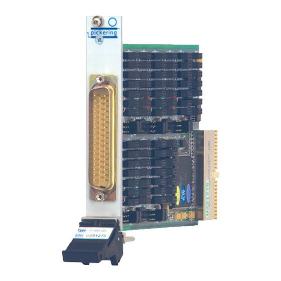
- Page 1 User Manual Programmable High Voltage Attenuator (Model No. 41-660/661) Issue 2.4 June 2017 pickeringtest.com pickering PROGRAMMABLE HIGH VOLTAGE ATTENUATOR 41-660/661 Page 1...
- Page 2 © COPYRIGHT (2017) PICKERING INTERFACES. ALL RIGHTS RESERVED. No part of this publication may be reproduced, transmitted, transcribed, translated or stored in any form, or by any means without the written permission of Pickering Interfaces. Technical details contained within this publication are subject to change without notice.
- Page 3 Pickering Interfaces strives to fulfil all relevant environmental laws and regulations and reduce wastes and releases to the environment. Pickering Interfaces aims to design and operate products in a way that protects the environment and the health and safety of its employees, customers and the public. Pickering Interfaces endeavours to develop and manufacture products that can be produced, distributed, used and recycled, or disposed of, in a safe and environmentally friendly manner.
-
Page 4: Product Safety
PRODUCT SAFETY SAFETY SYMBOLS The following safety symbols may be used on the product and throughout the product documentation. MEANING / DESCRIPTION SYMBOL PROTECTIVE EARTH (GROUND) To identify any terminal which is intended for connection to an external conductor for protection against electric shock in case of a fault, or the terminal of a protective earth (ground) electrode. -
Page 5: Table Of Contents
Pre Operation Checks ............3.1 Hardware Installation ............3.2 Software Installation .............3.2 Section 4 Programming Guide ............4.1 Programming Options For Pickering PXI Cards..4.1 Soft Front Panel ............4.3 Section 5 Connector Information ............5.1 Section 6 Trouble Shooting ..............6.1 Section 7 Maintenance Information ........... - Page 6 THIS PAGE INTENTIONALLY BLANK PROGRAMMABLE HIGH VOLTAGE ATTENUATOR 41-660/661 Page vi...
-
Page 7: Technical Specification
SECTION 1 - TECHNICAL SPECIFICATION pickering SECTION 1 - TECHNICAL SPECIFICATION 41-660/661 Programmable High Voltage Attenuator ● High Input Impedance ● 600 Volt Input Rating ● Available With Single or Differential Input Configurations ● Buffered Single Ended Output Signal Provides Low Output Impedance ●... - Page 8 5-Channel Differential High Voltage Attenuator 41-661-001 41-660: 10 off (Single Ended) 41-661: 5 off (Differential) Other versions can be supplied with lower channel count or different input impedance. Please contact your Pickering Maximum Input Voltage: ±600V Interface sale office with your requirements. Input Impedance 41-660: 1MΩ...
- Page 9 All modules are fully CE compliant and meet applicable EU Systems such as LabVIEW RT. For other RTOS support directives: Low-voltage safety EN61010-1:2001, contact Pickering. These drivers may be used with a variety of EMC Immunity EN61000-6-1:2001, Emissions EN55011:1998. programming environments and applications including: —...
- Page 10 SECTION 1 - TECHNICAL SPECIFICATION pickering THIS PAGE INTENTIONALLY BLANK Page 1.4 PROGRAMMABLE HIGH VOLTAGE ATTENUATOR 41-660/661...
-
Page 11: Technical Description
SECTION 2 - TECHNICAL DESCRIPTION pickering SECTION 2 - TECHNICAL DESCRIPTION FUNCTIONAL DESCRIPTION A functional block diagram is provided in Figure 2.1. The Module is powered by a +5V input via Compact PCI connector J1. The signal interface to the attenuator is via the front panel mounted 50-pin D-type male connector, J2. - Page 12 SECTION 2 - TECHNICAL DESCRIPTION pickering THIS PAGE INTENTIONALLY BLANK Page 2.2 PROGRAMMABLE HIGH VOLTAGE ATTENUATOR 41-660/661...
-
Page 13: Installation
Modular products require installation in a suitable PXI/LXI chassis. The module is designed for indoor use only. PREOPERATION CHECKS (UNPACKING) 1. Check the module for transport damage and report any damage immediately to Pickering Interfaces. Do not attempt to install the product if any damage is evident. -
Page 14: Hardware Installation
For a system comprising more than one chassis, turn ON the last chassis in the system followed by the penultimate, etc, and finally turn ON the external controller or chassis containing the system controller. 9. For Pickering Interfaces modular LXI installation there is no requirement to use any particular power up sequence. -
Page 15: Programming Guide
SECTION 4 - PROGRAMMING GUIDE pickering SECTION 4 - PROGRAMMING GUIDE PROGRAMMING OPTIONS FOR PICKERING INTERFACES PXI CARDS Software drivers are supplied for Microsoft Windows operating systems, with specific support for the following development environments: Microsoft Visual Studio (VB, C++, C#) ●... -
Page 16: Soft Front Panel
With most drivers, before programming a Pickering card it is important to understand the basic architecture of Pickering cards. The switches on a Pickering card are organized into logical sub-units, each sub-unit containing a set of objects of similar type and use. These objects may be switches, digital outputs, digital inputs, resistors, power supplies etc, depending on the nature of the specific card. -
Page 17: Connector Information
SECTION 5 - CONNECTOR INFORMATION pickering SECTION 5 - CONNECTOR INFORMATION The front panel connector on the 41-660 and 41-661 Programmable Attenuator modules is shown in Figure 5.1. The pinout for the 41-660 Single Ended Attenuator is shown in Figure 5.2 and the pinout for the 41-661 Differential Attenuator is shown in Figure 5.3. - Page 18 SECTION 5 - CONNECTOR INFORMATION pickering 41-660-001 50-pin D-type Plug Signal Signal Signal Number Name Number Name Number Name CH1 I/P CH5 I/P CH9 I/P CH2 I/P CH6 I/P CH10 I/P CH1 O/P CH5 O/P CH9 O/P CH2 O/P CH6 O/P...
-
Page 19: Trouble Shooting
PCI configuration, highlighting any potential configuration problems. Specific details of all installed Pickering switch cards are included. All the installed Pickering switch cards should be listed in the “Pilpxi information” section - if one or more cards is missing it may be possible to determine the reason by referring to the PCI configuration dump contained in the report, but interpretation of this information is far from straightforward, and the best course is to contact Pickering support: support@pickeringtest.com, if possible... - Page 20 SECTION 6 - TROUBLE SHOOTING pickering THIS PAGE INTENTIONALLY BLANK Page 6.2 PROGRAMMABLE HIGH VOLTAGE ATTENUATOR 41-660/661...
-
Page 21: Maintenance Information
For PXI modules which are supported in one of Pickering Interfaces’ Modular LXI Chassis (such as the 60-102B and 60-103B) no module software update is required. If the module was introduced after the LXI chassis was manufactured the module may not be recognized, in this case the chassis firmware may need upgrading. - Page 22 SECTION 7 - MAINTENANCE INFORMATION pickering RL40 RL33 RL65 RL72 RL34 RL41 RL66 RL73 RL10 RL35 RL42 RL67 RL74 RL11 RL36 RL43 RL68 RL75 RL44 RL12 RL37 RL69 RL76 RL38 RL45 RL13 RL70 RL77 RL39 RL46 RL78 RL14 RL71 RL49...
Need help?
Do you have a question about the Pxi 41-660 and is the answer not in the manual?
Questions and answers