
Related Manuals for Pickering PXI 41-752


Summary of Contents for Pickering PXI 41-752
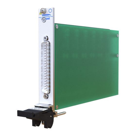
- Page 1 User Manual 6-Channel Battery Simulator Module (Model No. 41-752) Issue 4.0 January 2015 pickeringtest.com pickering 6-CHANNEL BATTERY SIMULATOR MODULE 41-752 Page (1)
- Page 2 © COPYRIGHT (2015) PICKERING INTERFACES. ALL RIGHTS RESERVED. No part of this publication may be reproduced, transmitted, transcribed, translated or stored in any form, or by any means without the written permission of Pickering Interfaces. Technical details contained within this publication are subject to change without notice.
- Page 3 Pickering Interfaces strives to fulfil all relevant environmental laws and regulations and reduce wastes and releases to the environment. Pickering Interfaces aims to design and operate products in a way that protects the environment and the health and safety of its employees, customers and the public. Pickering Interfaces endeavours to develop and manufacture products that can be produced, distributed, used and recycled, or disposed of, in a safe and environmentally friendly manner.
-
Page 4: Product Safety
PRODUCT SAFETY SAFETY SYMBOLS The following safety symbols may be used on the product and throughout the product documentation. MEANING / DESCRIPTION SYMBOL PROTECTIVE EARTH (GROUND) To identify any terminal which is intended for connection to an external conductor for protection against electric shock in case of a fault, or the terminal of a protective earth (ground) electrode. -
Page 5: Table Of Contents
Hardware Installation ............3.2 Software Installation .............3.2 Soft Front Panel Installation ..........3.3 Section 4 Programming Guide ..............4.1 Programming Options For Pickering PXI Cards....4.1 Programming For PXI ............4.1 Programming For LXI ............4.2 Programming The 40-752............4.3 Using the Soft Front Panel ...........4.7 Using The Battery Simulator In LabVIEW ......4.19 Section 5 Connector Information ..............5.1... - Page 6 THIS PAGE INTENTIONALLY BLANK 6-CHANNEL BATTERY SIMULATOR MODULE 41-752 Page (VI)
-
Page 7: Warnings And Cautions
Unused slots in the PXI/LXI chassis are populated with blanking plates to prevent access to user I/O signals that may be present. Blanking panels are available to order from Pickering in a variety of slot widths. If the product is not used in this manner for example by using an extender card then additional care must be taken to avoid contact with exposed signals. - Page 8 THIS PAGE INTENTIONALLY BLANK 6-CHANNEL BATTERY SIMULATOR MODULE 41-752 Page (VIII)
-
Page 9: Technical Specification
The user connector is a 37-way high voltage D Type which generation when using many series connected modules is fully supported by the wide range of Pickering Interfaces that provide high output voltages and providing a means of connector accessories. - Page 10 SECTION 1 - TECHNICAL SPECIFICATION pickering Specification Power Requirements from PXI Power Supply Number of Channels: 6 independent isolated channels. +3.3V +12V -12V Output Voltage Range: 0 to 7V, settable with 14-bit 0.8A 2.0A 0.6A 0.3A resolution (approximately 0.43mV). At maximum load for all channels, Output Voltage Accuracy: ±0.2% ±20mV from 1V to 7V output...
- Page 11 Programming PXI & CompactPCI Compliance Pickering provide kernel, IVI and VISA (NI and Agilent) drivers The module is compliant with the PXI Specification 2.2. Local which are compatible with 32/64-bit versions of Windows Bus, Trigger Bus and Star Trigger are not implemented.
- Page 12 SECTION 1 - TECHNICAL SPECIFICATION pickering THIS PAGE INTENTIONALLY BLANK 6-CHANNEL BATTERY SIMULATOR MODULE 41-752 Page 1.4...
-
Page 13: Technical Description
SECTION 2 - TECHNICAL DESCRIPTION pickering SECTION 2 - TECHNICAL DESCRIPTION MECHANICAL DESCRIPTION The 41-752 Battery Simulator Module conforms to the 3U height (128mm) Eurocard standard. Each module comprises: • CPCI Ejector Handle • Front Panel mounted 37-Way D-Type connector •... -
Page 14: Functional Description
SECTION 2 - TECHNICAL DESCRIPTION pickering FUNCTIONAL DESCRIPTION The 41-752 is a six channel battery simulator designed to simulate the performance of six separate batteries and is suitable for testing equipment that employ a battery stack. Vout + PXI Supply... -
Page 15: Using The 41-752 Battery Simulator
SECTION 2 - TECHNICAL DESCRIPTION pickering USING THE 41-752 BATTERY SIMULATOR Sense Line Connections The two sense lines for each channel of the battery simulator should be connected to the remote load so the battery simulator corrects for any voltage drop in the connecting wires. If the sense wires are not connected to the remote load the battery simulator will sense the voltage at the module front panel and regulate the voltage to the requested value. - Page 16 41-752 modules. These chassis have adequate PSU and cooling capacity to be fully populated by 41-752 modules and are the chassis that Pickering Interfaces has tested the modules in. The chassis should be set to maximum fan speed, and if desk mounted, the front feet should be raised to allow maximum air flow.
-
Page 17: 41-752 Interlock System
Master Module’s Module Enable and then turn on each battery simulator through its Module Enable. To avoid high dynamic loads on the chassis backplane Pickering Interfaces recommends that each module is restarted in a sequence that avoids an excessively high rate of PSU load change. - Page 18 SECTION 2 - TECHNICAL DESCRIPTION pickering +3.3V +3.3V +3.3V 41-752 41-752 41-752 BATTERY BATTERY BATTERY Enable Enable Enable SIMULATOR SIMULATOR SIMULATOR MODULE MODULE MODULE Status Status Status PXI Gnd PXI Gnd PXI Gnd To Other 41-752 Modules Figure 2.4 - All 41-752 Modules Enabled by a Common Signal MASTER +3.3V...
-
Page 19: Connecting Battery Simulator Channels In Series
In a typical application 16 modules can be connected in series to simulate a 96 channel battery stack. Pickering Interfaces recommends that the 6 channels of the 41-752 are wired together (so each module provides a contiguous stack of 6 battery channels in series) in order to make the operation of the system easier to understand and to minimize the inter-channel voltage on each module. -
Page 20: Battery Simulator On/Off Control
SECTION 2 - TECHNICAL DESCRIPTION pickering BATTERY SIMULATOR ON/OFF CONTROL Each channel of the 41-752 can be independently turned off. Users need to recognise real life batteries do not “turn off” in the way a relay (for example) does. If a channel is off it cannot provide any current to the load and it will effectively disconnect the entire battery stack from the load. -
Page 21: Accessories
ACCESSORIES Pickering Interfaces offer a range of break out boxes that support all the connectors used on its products. These break out boxes provide a simple way of connecting to fully enclosed terminal blocks rather than directly to the D Type connector and they incorporate cable grips to resist wire breakage. - Page 22 SECTION 2 - TECHNICAL DESCRIPTION pickering THIS PAGE INTENTIONALLY BLANK 6-CHANNEL BATTERY SIMULATOR MODULE 41-752 Page 2.10...
-
Page 23: Installation
Modular products require installation in a suitable PXI/LXI chassis. The module is designed for indoor use only. PREOPERATION CHECKS (UNPACKING) 1. Check the module for transport damage and report any damage immediately to Pickering Interfaces. Do not attempt to install the product if any damage is evident. -
Page 24: Hardware Installation
For a system comprising more than one chassis, turn ON the last chassis in the system followed by the penultimate, etc, and finally turn ON the external controller or chassis containing the system controller. 9. For Pickering Interfaces modular LXI installation there is no requirement to use any particular power up sequence. -
Page 25: Soft Front Panel Installation
Pickering directory created during driver installation (usually C:\Pickering). 3. Once installed a new program group should be available on the ‘Programs > Pickering’ menu location. This will install the soft front panel utility and the corresponding windows help file. - Page 26 SECTION 3 - INSTALLATION pickering THIS PAGE INTENTIONALLY BLANK 6-CHANNEL BATTERY SIMULATOR MODULE 41-752 Page 3.4...
-
Page 27: Programming Guide
IVI Driver for Windows - pi40iv The pi40iv IVI (Interchangeable Virtual Instrument) driver supports all Pickering Interfaces PXI switch cards that are consistent with the Iviswtch class model - as are the great majority of cards in the System 40/45/50 ranges. It integrates well with LabWindows/CVI and LabVIEW, and is fully compatible with Switch Executive. -
Page 28: Programming For Lxi
Pickering LXI products include an SSH interface which allows remote command line access to control cards, or, using a suitable package, programmatic control. The user is advised to visit the Pickering web site for further details of all the above drivers, where documentation, example programs, and further help with driver choice are available. -
Page 29: Programming The 40-752
PROGRAMMING THE 41-752 The 41-752 Battery Simulator uses the same driver software as the Pickering range of switches, pilpxi or pipx40, requiring version 3.05 or later. There is no IVI driver available for this unit at present. For full detail of the range of driver functions available the user is advised to refer to documentation for the switch drivers pilpxi and/or pipx40. - Page 30 SECTION 4 - PROGRAMMING GUIDE pickering SET AND READ BACK A SINK CURRENT C code example using the Direct Driver (requires Pilpxi.h and Pilpxi.lib found in the Pickering folder structure) DWORD l_CardNum; //assumed you have opened the card using OpenCards() or OpenSpecifiedCard() DWORD l_SubUnit; double l_Val; SubUnit = 3;...
- Page 31 SECTION 4 - PROGRAMMING GUIDE pickering //Start a loop //prompts for a test value to be placed in l_Val 0=low voltage 0x3fff is highest voltage //exit the loop if 0 Volts achieved l_RetCode = PIL_WriteSub(l_CardNum, l_SubUnit, &l_Val); //write the value in l_Val to the DAC //Use a DMM to check voltage on channel 3 output pins is 0 volts //loop for another test CalInd= 1;...
- Page 32 SECTION 4 - PROGRAMMING GUIDE pickering Output Sub-UnitS 7 to 12 - Current Sinks for channels 1 to 6 Each of these sub-units appear as a 16 bit register, each bit represents one element of a bank of parallel current sinks, each element draws current (nominally 6.25mA) from the input.
-
Page 33: Using The Soft Front Panel
USING THE SOFT FRONT PANEL Getting Started Run the Pickering Interfaces Multiple Battery Simulator SFP by double-clicking the icon in the application folder. The Multiple Battery Simulator SFP starts up (while loading, the initial window appears, see Figure 4.1) and you should see a display similar to Figure 4.2. - Page 34 SECTION 4 - PROGRAMMING GUIDE pickering Demo Mode Select the Demo option (Figure 4.4). The combo box with simulation cards available is now enabled as well as the Open button. Select a card from the list (Figure 4.5) and click on the Open button to start a simulation with the specified card.
- Page 35 SECTION 4 - PROGRAMMING GUIDE pickering Select the PXI option (Figure 4.6). The Find cards button is now enabled. Click on this button to find all the available Battery Simulator cards fitted in the connected PXI device. If suitable cards are fitted, they will be listed in the combo box.
- Page 36 SECTION 4 - PROGRAMMING GUIDE pickering Select the LXI option (Figure 4.7). The empty text field and the button with three dots are now enabled. You can type the IP address of the LXI device directly into the text field, or you can click on the button with three dots to use the discovery mechanism to find the LXI devices.
- Page 37 SECTION 4 - PROGRAMMING GUIDE pickering Figure 4.9 - The discovery window After selection of the LXI device, the Find cards button is enabled on the SFP. Click on this button to find all available cards of the Battery Simulator type in the connected LXI device. If there are suitable cards, they will be listed in the combo box (similar to Figure 4.10).
- Page 38 SECTION 4 - PROGRAMMING GUIDE pickering Controlling The Card To control the card, you can use the rotary controls and two way switch control (Figure 4.13), the controls in the Global groupbox (Figure 4.17) or direct entry using digits (Figure 4.14). Be aware that the SFP is designed to operate several different types of Battery Simulator and certain controls may not be enabled for a particular card.
- Page 39 SECTION 4 - PROGRAMMING GUIDE pickering You can use the rotary controls (Figure 4.13) to set the Voltage Source, Current Sink and Output Resistance of the Battery Simulator. You can also use the arrow keys and Page Up / Page Down keys to control the selected knob.
- Page 40 SECTION 4 - PROGRAMMING GUIDE pickering If the Battery Simulator card has more than one channel, the Channel selector box will be visible (Figure 4.16), which allows you to select the channel (subunit) to be controlled. Figure 4.16 - The channel selector box of the SFP Also, for Battery Simulators with multiple channels, the Global settings group box (Figure 4.17) allows you to set...
- Page 41 SECTION 4 - PROGRAMMING GUIDE pickering Calibration WARNING: FOR AUTHORIZED PERSONEL ONLY All Battery Simulator cards are calibrated at the factory before delivery. But if recalibration is required, Calibration can be selected from the Options menu (see Figure 4.21). For more information how to calibrate the Battery Simulator see Section 7 of this manual.
- Page 42 SECTION 4 - PROGRAMMING GUIDE pickering Load and Save You can save the current state of the SFP by selecting the Save or Save as... from the File menu (Figure 4.22). You can also load a previously saved state of the SFP by selecting Load from the File menu.
- Page 43 SECTION 4 - PROGRAMMING GUIDE pickering Settings You can change settings of the SFP by clicking on Settings from the menu Options (Figure 4.23). Figure 4.23 - The Options menu of the SFP with “Settings” selected Figure 4.24 - The Settings window of the SFP You can change the Broadcast Echo port, Broadcast Echo timeout, Direct Echo port, etc (Figure 4.24).
- Page 44 SECTION 4 - PROGRAMMING GUIDE pickering Help From the Help menu you can click on Contents to display the help document, alternatively, press the F1 function key. Clicking on About (Figure 4.25) opens a new window displaying information about the application (Figure 4.26) including all cards supported by the SFP and the assemblies used.
-
Page 45: Using The Battery Simulator In Labview
USING THE BATTERY SIMULATOR IN LabVIEW Finding the Driver During driver installation Pickering LabVIEW libraries are installed into the ‘instr.lib’ folder of the LabVIEW installation. This is accessed from the ‘Instrument I/O’ – ‘Instr Drivers’ palette in LabVIEW. The LXI driver package is shown above, however similar palettes are available from the pipx40 (PXI-VISA) palette and from the pilpxi (PXI-non-VISA) palette. - Page 46 SECTION 4 - PROGRAMMING GUIDE pickering First a connection is made to the chassis containing the Battery Simulator, in the example shown the card is mounted in a locally connected PXI chassis, so the address ‘PXI’ is provided. If the card were in an LXI chassis then the IP address of that chassis would be used instead.
- Page 47 SECTION 4 - PROGRAMMING GUIDE pickering Controlling Multiple Channels on a Card The previous example controlled a single channel of the Battery Simulator, however many functions may also be used to set all channels simultaneously. In this example, the channel number is set to 0, which is taken to mean ‘all channels’ by the driver. So, in this example, all channels will be set to 2.345V and 0.05A.
- Page 48 SECTION 4 - PROGRAMMING GUIDE pickering THIS PAGE INTENTIONALLY BLANK 6-CHANNEL BATTERY SIMULATOR MODULE 41-752 Page 4.22...
- Page 49 SECTION 5 - CONNECTOR INFORMATION pickering SECTION 5 - CONNECTOR INFORMATION 37-Way D-Type Plug Pin No. Signal Name Pin No. Signal Name -Output CH1 +Output CH1 -Sense CH1 +Sense CH1 -Output CH2 +Output CH2 -Sense CH2 +Sense CH2 -Output CH3...
- Page 50 SECTION 5 - CONNECTOR INFORMATION pickering THIS PAGE INTENTIONALLY BLANK 6-CHANNEL BATTERY SIMULATOR MODULE 41-752 Page 5.2...
-
Page 51: Trouble Shooting
PCI configuration, highlighting any potential configuration problems. Specific details of all installed Pickering switch cards are included. All the installed Pickering switch cards should be listed in the “Pilpxi information” section - if one or more cards is missing it may be possible to determine the reason by referring to the PCI configuration dump contained in the report, but interpretation of this information is far from straightforward, and the best course is to contact Pickering support: support@pickeringtest.com, if possible... - Page 52 SECTION 6 - TROUBLE SHOOTING pickering THIS PAGE INTENTIONALLY BLANK 6-CHANNEL BATTERY SIMULATOR MODULE 41-752 Page 6.2...
-
Page 53: Maintenance Information
For PXI modules which are supported in one of Pickering Interfaces’ Modular LXI Chassis (such as the 60-102B and 60-103B) no module software update is required. If the module was introduced after the LXI chassis was manufactured the module may not be recognized, in this case the chassis firmware may need upgrading. -
Page 54: Calibration Procedure
Required test Equipment One or two DMM’s, 100µV or better resolution on DC voltage. Most 5½ digit DMM’s will meet the ● requirement. 37-way D-Type connector assembly, recommended Pickering part 40-965-037 ● Test Procedure Output Voltage Check Connect a load to the output connector of the 41-752 module as shown in Figure 7.1. - Page 55 SECTION 7 - MAINTENANCE INFORMATION pickering 1Ω Vout+ 36Ω CHANNEL 1 41-752 Load BATTERY SIMULATOR Vout- MODULE 1Ω Figure 7.1 - Load Connection For Testing 41-752 Battery Simulator Sense Line Operation Connect the load as shown in Figure 7.1 to the channel under test.
- Page 56 SECTION 7 - MAINTENANCE INFORMATION pickering Sense Line Operation Current Measurement – 41-752 POWER SUPPLY BATTERY Voltage WITH VARIABLE CHANNEL 1 SIMULATOR Measurement CURRENT LIMIT MODULE – – Figure 7.3 - Setup For Testing The 41-752 Battery Simulator’s Current Sink Connect the channel under test to a power supply with variable current limit, set the power supply current limit to 0mA (or <10mA) and the output voltage to 6V...
-
Page 57: Test Results
SECTION 7 - MAINTENANCE INFORMATION pickering TEST RESULTS The following pages can be printed and used to record the results of the calibration procedure. Part Number: Serial Number: Date of Calibration: Operator Name: Test Equipment Used: CHANNEL 1 Result Specification Limit ±0.2% ±20mV... - Page 58 SECTION 7 - MAINTENANCE INFORMATION pickering CHANNEL 2 Result Specification Limit ±0.2% ±20mV Set Output Measured Output Voltage (delete as Voltage appropriate) 1.0V 1.022 0.978 Pass / Fail 1.1V 1.1222 1.0778 Pass / Fail 1.2V 1.2224 1.1776 Pass / Fail 1.3V...
- Page 59 SECTION 7 - MAINTENANCE INFORMATION pickering CHANNEL 3 Result Specification Limit ±0.2% ±20mV Set Output Measured Output Voltage (delete as Voltage appropriate) 1.0V 1.022 0.978 Pass / Fail 1.1V 1.1222 1.0778 Pass / Fail 1.2V 1.2224 1.1776 Pass / Fail 1.3V...
- Page 60 SECTION 7 - MAINTENANCE INFORMATION pickering CHANNEL4 Result Specification Limit ±0.2% ±20mV Set Output Measured Output Voltage (delete as Voltage appropriate) 1.0V 1.022 0.978 Pass / Fail 1.1V 1.1222 1.0778 Pass / Fail 1.2V 1.2224 1.1776 Pass / Fail 1.3V 1.3226...
- Page 61 SECTION 7 - MAINTENANCE INFORMATION pickering CHANNEL 5 Result Specification Limit ±0.2% ±20mV Set Output Measured Output Voltage (delete as Voltage appropriate) 1.0V 1.022 0.978 Pass / Fail 1.1V 1.1222 1.0778 Pass / Fail 1.2V 1.2224 1.1776 Pass / Fail 1.3V...
- Page 62 SECTION 7 - MAINTENANCE INFORMATION pickering CHANNEL6 Result Specification Limit ±0.2% ±20mV Set Output Measured Output Voltage (delete as Voltage appropriate) 1.0V 1.022 0.978 Pass / Fail 1.1V 1.1222 1.0778 Pass / Fail 1.2V 1.2224 1.1776 Pass / Fail 1.3V 1.3226...
-
Page 63: Alignment Procedure
SECTION 7 - MAINTENANCE INFORMATION pickering ALIGNMENT PROCEDURE Caution: Adjustment of this module is not routinely required; if a user adjustment is performed then it is done so at the users’ risk, corruption of calibration data stored within the module could result in a return to factory event. - Page 64 SECTION 7 - MAINTENANCE INFORMATION pickering ALIGNMENT TEST RECORD Part Number: Serial Number: Date of Alignment: Operator Name: Test Equipment Used: CHANNEL 1 Previous setting New setting Zero Voltage adjustment Maximum Voltage adjustment CHANNEL 2 Previous setting New setting Zero Voltage adjustment...
Need help?
Do you have a question about the PXI 41-752 and is the answer not in the manual?
Questions and answers