
Related Manuals for Pickering Pxi 41-750


Summary of Contents for Pickering Pxi 41-750
- Page 1 User Manual Battery Simulator Module (Model No. 41-750) Issue 7.1 June 2017 pickeringtest.com pickering BATTERY SIMULATOR MODULE 41-750 Page (1)
- Page 2 © COPYRIGHT (2017) PICKERING INTERFACES. ALL RIGHTS RESERVED. No part of this publication may be reproduced, transmitted, transcribed, translated or stored in any form, or by any means without the written permission of Pickering Interfaces. Technical details contained within this publication are subject to change without notice.
- Page 3 Pickering Interfaces strives to fulfil all relevant environmental laws and regulations and reduce wastes and releases to the environment. Pickering Interfaces aims to design and operate products in a way that protects the environment and the health and safety of its employees, customers and the public. Pickering Interfaces endeavours to develop and manufacture products that can be produced, distributed, used and recycled, or disposed of, in a safe and environmentally friendly manner.
-
Page 4: Product Safety
PRODUCT SAFETY SAFETY SYMBOLS The following safety symbols may be used on the product and throughout the product documentation. MEANING / DESCRIPTION SYMBOL PROTECTIVE EARTH (GROUND) To identify any terminal which is intended for connection to an external conductor for protection against electric shock in case of a fault, or the terminal of a protective earth (ground) electrode. -
Page 5: Table Of Contents
Hardware Installation ............3.2 Software Installation .............3.2 Soft Front Panel Installation ..........3.3 Section 4 Programming Guide ..............4.1 Programming Options For Pickering PXI Cards....4.1 Programming The Module ...........4.3 Module Architecture ..............4.3 Using The Soft Front Panel ..........4.9 Section 5 Connector Information ..............5.1 Section 6 Trouble Shooting .................6.1... - Page 6 THIS PAGE INTENTIONALLY BLANK BATTERY SIMULATOR MODULE 41-750 Page (VI)
-
Page 7: Warnings And Cautions
Unused slots in the PXI/LXI chassis are populated with blanking plates to prevent access to user I/O signals that may be present. Blanking panels are available to order from Pickering in a variety of slot widths. If the product is not used in this manner for example by using an extender card then additional care must be taken to avoid contact with exposed signals. - Page 8 THIS PAGE INTENTIONALLY BLANK BATTERY SIMULATOR MODULE 41-750 Page (VIII)
-
Page 9: Technical Specification
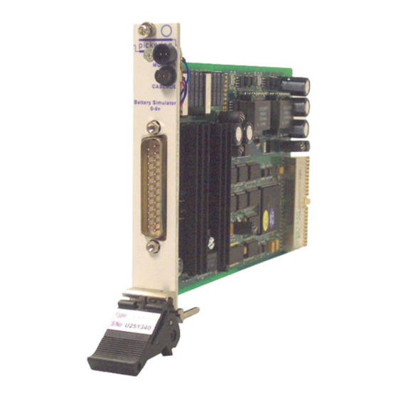
This facility can also be used to monitor other types of modules in the Pickering range. The wide bandwidth of the monitor facility allows the use of external data acquisition devices to capture voltage and current 41-750 PCB View variations with time. - Page 10 SECTION 1 - TECHNICAL SPECIFICATION pickering Specification Number of Channels: 1 (isolated) Output Voltage Range: 0 to 6 Volts (at front panel), isolated ±50V maximum common mode voltage. Voltage Resolution: Set with 16 bit resolution. Voltage Sense: Remote sensing of load voltage,...
- Page 11 All modules are fully CE compliant and meet applicable EU Systems such as LabVIEW RT. For other RTOS support directives: Low-voltage safety EN61010-1:2001, contact Pickering. These drivers may be used with a variety of EMC Immunity EN61000-6-1:2001, Emissions EN55011:1998. programming environments and applications including: —...
- Page 12 SECTION 1 - TECHNICAL SPECIFICATION pickering THIS PAGE INTENTIONALLY BLANK BATTERY SIMULATOR MODULE 41-750 Page 1.4...
-
Page 13: Technical Description
SECTION 2 - TECHNICAL DESCRIPTION pickering SECTION 2 - TECHNICAL DESCRIPTION FUNCTIONAL DESCRIPTION The 41-750 is a single channel battery simulator designed to simulate the performance of a battery when testing portable equipment such as mobile phones. Vout + Linear... -
Page 14: Guidance On Using The Module
SECTION 2 - TECHNICAL DESCRIPTION pickering GUIDANCE ON USING THE MODULE Sense Line Configuration The sense lines for the 41-750 ensure that the module can regulate the voltage at a remote load. The sense lines are manually configured in one of two ways using jumpers on the PCB: If one or both the sense lines are not connected to the load the battery simulator closes down the ●... - Page 15 SECTION 2 - TECHNICAL DESCRIPTION pickering Transient Load Response The 41-750 has been designed to provide very fast recovery from transient loads. However, if the load has an excessively large capacitive component then charging this capacitance can limit the response time. The power supply includes an internal 22µF load.
- Page 16 DMM voltage barrier technology and not easily reproduced within a power supply module. Connecting Monitor Ports Together The diagrams below show how the monitor ports of two Pickering devices can be connected to allow a single DMM access to all modules with a single connection.
- Page 17 PIM Out Figure 2.4 - Connecting Modules Together Pickering can supply cables ready made to provide the connections. This description of the monitor facility assumes that the user is using the two pin front panel connectors. This may not always be the case since the retention force of this simple connector is not high.
- Page 18 Accessories Pickering Interfaces offer a range of break out boxes that support all the types of connector used on its products. These break out boxes provide a simple way of connecting to fully enclosed terminal blocks, they also incorporate cable grips to resist wire breakage.
-
Page 19: Installation
Modular products require installation in a suitable PXI/LXI chassis. The module is designed for indoor use only. PREOPERATION CHECKS (UNPACKING) 1. Check the module for transport damage and report any damage immediately to Pickering Interfaces. Do not attempt to install the product if any damage is evident. -
Page 20: Hardware Installation
For a system comprising more than one chassis, turn ON the last chassis in the system followed by the penultimate, etc, and finally turn ON the external controller or chassis containing the system controller. 9. For Pickering Interfaces modular LXI installation there is no requirement to use any particular power up sequence. -
Page 21: Soft Front Panel Installation
2. Follow the on screen instructions, selecting a different target directory if required. It is recommended that it be installed to the default Pickering directory created during driver installation (usually C:\Pickering). 3. Once installed a new program group should be available on the Programs\Pickering Interfaces Ltd menu location. - Page 22 SECTION 3 - INSTALLATION pickering THIS PAGE INTENTIONALLY BLANK BATTERY SIMULATOR MODULE 41-750 Page 3.4...
-
Page 23: Programming Guide
IVI Driver for Windows - pi40iv The pi40iv IVI (Interchangeable Virtual Instrument) driver supports all Pickering Interfaces PXI switch cards that are consistent with the Iviswtch class model - as are the great majority of cards in the System 40/45/50 ranges. It integrates well with LabWindows/CVI and LabVIEW, and is fully compatible with Switch Executive. - Page 24 Pickering LXI products include an SSH interface which allows remote command line access to control cards, or, using a suitable package, programmatic control. The user is advised to visit the Pickering web site for further details of all the above drivers, where documentation, example programs, and further help with driver choice are available.
-
Page 25: Programming The Module
PROGRAMMING THE MODULE The 41-750 Battery Simulator uses the same driver software as the Pickering range of switches, pilpxi or pipx40, requiring version 2.51 or later. There is no IVI driver available for this unit at present. For full detail of the range of driver functions available the user is advised to refer to documentation for the switch drivers pilpxi and/or pipx40. - Page 26 SECTION 4 - PROGRAMMING GUIDE pickering Output Sub-Unit 1 - Monitor Controls the switching associated with the monitor selection. It appears as a 4-way multiplex of which a maximum of one output may be selected. The outputs are as follows:...
- Page 27 SECTION 4 - PROGRAMMING GUIDE pickering Output Sub-Unit 3 - Voltage Source This is a 16 bit register which can be set to any binary value between 0 and 65535 (0xFFFF hexadecimal). The range of values controls the output voltage between its minimum and maximum values, nominally 0-6Volts.
- Page 28 SECTION 4 - PROGRAMMING GUIDE pickering Output Sub-Unit 5 - Low Voltage Offset As sub-unit 4 but controls the lower end of the output voltage range. Output Sub-Unit 6 - High Voltage Non-Volatile Store Controls the non-volatile storage of calibration for the upper end of the output voltage range. It is an 8 bit register which may be set from 0 to 255 (0xFF hexadecimal).
- Page 29 SECTION 4 - PROGRAMMING GUIDE pickering Input Sub-Unit 1 - Indicators This sub-unit is 1 bit wide and contains the indicator flag that shows the state of the overload condition of the module. This may be read either with a bit-width function or a dword-width function.
- Page 30 SECTION 4 - PROGRAMMING GUIDE pickering Input Sub-Unit 2 - High Voltage Calibration Value The non-volatile value of the high voltage calibration may be read back from this 8 bit sub-unit. For example, the following commands will read the non volatile high voltage calibration value. Input sub-units 3 and 4 operate in the same way, simply change the number of the second parameter.
-
Page 31: Using The Soft Front Panel
USING THE SOFT FRONT PANEL Getting Started Run the Pickering Interfaces Multiple Battery Simulator SFP by double-clicking the icon in the application folder. The Multiple Battery Simulator SFP starts up (while loading, the initial window appears, see Figure 4.1) and you should see a display similar to Figure 4.2. - Page 32 SECTION 4 - PROGRAMMING GUIDE pickering Demo Mode Select the Demo option (Figure 4.4). The combo box with simulation cards available is now enabled as well as the Open button. Select a card from the list (Figure 4.5) and click on the Open button to start a simulation with the specified card.
- Page 33 SECTION 4 - PROGRAMMING GUIDE pickering Select the PXI option (Figure 4.6). The Find cards button is now enabled. Click on this button to find all the available Battery Simulator cards fitted in the connected PXI device. If suitable cards are fitted, they will be listed in the combo box.
- Page 34 SECTION 4 - PROGRAMMING GUIDE pickering Select the LXI option (Figure 4.7). The empty text field and the button with three dots are now enabled. You can type the IP address of the LXI device directly into the text field, or you can click on the button with three dots to use the discovery mechanism to find the LXI devices.
- Page 35 SECTION 4 - PROGRAMMING GUIDE pickering Figure 4.9 - The discovery window After selection of the LXI device, the Find cards button is enabled on the SFP. Click on this button to find all available cards of the Battery Simulator type in the connected LXI device. If there are suitable cards, they will be listed in the combo box (similar to Figure 4.10).
- Page 36 SECTION 4 - PROGRAMMING GUIDE pickering Controlling The Module To control the module, you can use the rotary controls and two way switch control (Figure 4.13), the controls in the Global groupbox (Figure 4.17) or direct entry using digits (Figure 4.14). Be aware that the SFP is designed to operate several different types of Battery Simulator and certain controls may not be enabled for a particular module.
- Page 37 SECTION 4 - PROGRAMMING GUIDE pickering You can use the rotary controls (Figure 4.13) to set the Voltage Source, Current Sink and Output Resistance of the Battery Simulator. You can also use the arrow keys and Page Up / Page Down keys to control the selected knob.
- Page 38 SECTION 4 - PROGRAMMING GUIDE pickering If the Battery Simulator module has more than one channel, the Channel selector box will be visible (Figure 4.16), which allows you to select the channel (subunit) to be controlled. Figure 4.16 - The channel selector box of the SFP Also, for Battery Simulators with multiple channels, the Global settings group box (Figure 4.17) allows you to set...
- Page 39 SECTION 4 - PROGRAMMING GUIDE pickering Calibration WARNING: FOR AUTHORIZED PERSONEL ONLY All Battery Simulator modules are calibrated at the factory before delivery. But if recalibration is required, Calibration can be selected from the Options menu (see Figure 4.21). For more information how to calibrate the Battery Simulator see Section 7 of this manual.
- Page 40 SECTION 4 - PROGRAMMING GUIDE pickering Load and Save You can save the current state of the SFP by selecting the Save or Save as... from the File menu (Figure 4.22). You can also load a previously saved state of the SFP by selecting Load from the File menu.
- Page 41 SECTION 4 - PROGRAMMING GUIDE pickering Settings You can change settings of the SFP by clicking on Settings from the menu Options (Figure 4.23). Figure 4.23 - The Options menu of the SFP with “Settings” selected Figure 4.24 - The Settings window of the SFP You can change the Broadcast Echo port, Broadcast Echo timeout, Direct Echo port, etc (Figure 4.24).
- Page 42 SECTION 4 - PROGRAMMING GUIDE pickering Help From the Help menu you can click on Contents to display the help document, alternatively, press the F1 function key. Clicking on About (Figure 4.25) opens a new window displaying information about the application (Figure 4.26) including all modules supported by the SFP and the assemblies used.
- Page 43 SECTION 5 - CONNECTOR INFORMATION pickering SECTION 5 - CONNECTOR INFORMATION Monitor A+ is electrically connected to Monitor+ Monitor B- is electrically connected to Monitor- MONITOR Cascade A+ is electrically connected to Cascade_Monitor+ Cascade B- is electrically connected to Cascade_Monitor-...
- Page 44 SECTION 5 - CONNECTOR INFORMATION pickering THIS PAGE INTENTIONALLY BLANK BATTERY SIMULATOR MODULE 41-750 Page 5.2...
-
Page 45: Trouble Shooting
PCI configuration, highlighting any potential configuration problems. Specific details of all installed Pickering switch cards are included. All the installed Pickering switch cards should be listed in the “Pilpxi information” section - if one or more cards is missing it may be possible to determine the reason by referring to the PCI configuration dump contained in the report, but interpretation of this information is far from straightforward, and the best course is to contact Pickering support: support@pickeringtest.com, if possible... - Page 46 SECTION 6 - TROUBLE SHOOTING pickering THIS PAGE INTENTIONALLY BLANK BATTERY SIMULATOR MODULE 41-750 Page 6.2...
-
Page 47: Maintenance Information
For PXI modules which are supported in one of Pickering Interfaces’ Modular LXI Chassis (such as the 60-102B and 60-103B) no module software update is required. If the module was introduced after the LXI chassis was manufactured the module may not be recognized, in this case the chassis firmware may need upgrading. -
Page 48: Calibration Procedure
The test is designed to ensure that the product is fully functional and is based on the use of a set of Pickering Interfaces load cards and standard cables that can be purchased through your local Pickering Interfaces sales office. -
Page 49: Test Procedure
SECTION 7 - MAINTENANCE INFORMATION pickering TEST PROCEDURE Output Voltage Check Connect a load that draws a current of 2.8 Amps at 6V (2.14Ω) and is capable of dissipating 16.8 Watts directly to the front panel connector of the battery simulator. Also, the sense lines from the front panel connector should be connected directly to the load. - Page 50 SECTION 7 - MAINTENANCE INFORMATION pickering Measurement Result Specification Load Voltage Should be within 5mV of Monitor sense voltage measured load voltage Should be greater than measured load voltage, Monitor output voltage typically by 10mV when using recommended lead 54.5mV nominal...
-
Page 51: Test Results
SECTION 7 - MAINTENANCE INFORMATION pickering TEST RESULTS This page can be printed and used to record the results of a calibration procedure. Part Number: Serial Number: Date of Calibration: Operator’s Name: Test Equipment Used Voltage Test with 2.14Ω Load Specification limit (0.1% ±... - Page 52 SECTION 7 - MAINTENANCE INFORMATION pickering Monitor Check at 5V Output Measurement Result Specification Load Voltage Should be within 5mV of Monitor sense voltage measured load voltage Should be greater than measured load voltage, Monitor output voltage typically by 10mV when using recommended lead 54.5mV nominal...
-
Page 53: Alignment Procedure
SECTION 7 - MAINTENANCE INFORMATION pickering ALIGNMENT PROCEDURE Install the module in the chassis and launch the Soft Front Panel. Next, launch the Calibration Soft Front Panel by selecting Calibration from the Options menu. The Calibration Soft Front Panel will pop up as shown in Figure 7.2. -
Page 54: Alignment Test Record
SECTION 7 - MAINTENANCE INFORMATION pickering ALIGNMENT TEST RECORD Part Number: Serial Number: Date of Calibration: Operator’s Name: Test Equipment Used Previous setting New setting Zero Voltage adjustment Maximum Voltage adjustment BATTERY SIMULATOR MODULE 41-750 Page 7.8...
Need help?
Do you have a question about the Pxi 41-750 and is the answer not in the manual?
Questions and answers